to the best of our knowledge, no existing security architecture for object based .... of popular software are released, or when application servers are subject to distribute denial of ...... means of reverse access control, and by means of auditing. ...... [117] Stephen T. Kent, Charles Lynn, Joanne Mikkelson, and Karen Seo. Se-.
Design and Implementation of a Secure Wide-Area Object Middleware Bogdan C. Popescu
Advanced School for Computing and Imaging
This work was carried out in the ASCI graduate school. ASCI dissertation series number 150.
Doctoral committee: prof.dr. A.S. Tanenbaum (promotor) dr. B. Crispo (copromotor) prof.dr. B. Christianson (University of Hertfordshire, UK) prof.dr. J. Bacon (University of Cambridge, UK) prof.dr. F. Brazier (Vrije Universiteit, Amsterdam) prof.dr. M. van Steen (Vrije Universiteit, Amsterdam) dr. H. Bos (Vrije Universiteit, Amsterdam)
A summary of this thesis has been published in the Elsevier International Journal of Computer and Telecommunications Networking. Parts of Chapter 4 have been published in the Proceedings of the 18th Annual Computer Security Applications Conference. Parts of Chapter 6 have been published in the Proceedings of the 9th Australasian Conference on Information Security and Privacy, and in the Proceedings of the 2004 ACM Workshop on Digital Rights Management. Parts of Chapter 7 have been published in the Proceedings of the 11th International Security Protocols Workshop. Parts of Chapter 8 have been published in the Proceedings of the 9th USENIX Workshop on Hot Topics in Operating Systems.
c Copyright 2007 by Bogdan C. Popescu
VRIJE UNIVERSITEIT
DESIGN AND IMPLEMENTATION OF A SECURE WIDE-AREA OBJECT MIDDLEWARE
ACADEMISCH PROEFSCHRIFT ter verkrijging van de graad Doctor aan de Vrije Universiteit Amsterdam, op gezag van de rector magnificus prof.dr. L.M. Bouter, in het openbaar te verdedigen ten overstaan van de promotiecommissie van de faculteit der Exacte Wetenschappen op woensdag 5 september 2007 om 10.45 uur in het auditorium van de universiteit, De Boelelaan 1105
door
Bogdan Costin Popescu geboren te Boekarest, Roemeni¨e
promotor: copromotor:
prof.dr. A.S. Tanenbaum dr. B. Crispo
Acknowledgments I would like to thank my advisors, Prof. Andrew S. Tanenbaum and Dr. Bruno Crispo for their support and encouragement. Andy has been a great inspiration: as an advisor, he gave me a lot of freedom in pursuing a variety of research topics, and spent countless hours helping me to sort through half-baked ideas; he also taught me some of the secrets of writing great research papers. From Bruno I learned a lot about computer security; he has also guided me trough the elaborate process of writing research proposals and applying for funding. I feel extremely lucky to have had such great advisors! I would also like to thank the members of my doctoral committee: Prof. Bruce Christianson, Prof. Jean Bacon, Prof. Frances Brazier, Prof. Maarten van Steen, and Dr. Herbert Bos. The quality of this thesis has greatly improved thanks to your comments and suggestions! I would like to mention my former colleagues at the Vrije Universitieit: Melanie, Srijith, Jorrit, Ben, Guido, Arno, Gerco, Ihor, Philip, Daniela, Swami, Michal, Spyros, Gosia, Chandana, Guillaume, and Jan-Mark. We had some “gezellig” time during these years, and I will miss you all. Best of luck wherever you will continue your career! Special thanks to Jan-Mark for proofreading the “samenvatting” of this thesis. I would also like to mention my friends in Amsterdam: Daniel (S.P.), Norel, Paul, Daniel (I.), Maria, Femke, Sofia, Krisztina, Andrei, Roy, Radu, Stan, Borys, Eduardo, and Didier. You have all been great friends, and made my study years in Amsterdam very agreeable! Very special thanks to Liza for her warm support and constant encouraging, especially during the most difficult time when I was writing this thesis. It would have been so much harder to finish this without you, lekker ding! Finally, I would like to thank my family—mami, tati, buni, and Ionut—for their moral support during all these years. Since I can ever remember, my parents have stimulated my thirst for knowledge, and have always encouraged me to excel. I owe you a great deal of everything I have accomplished!
iii
iv
ACKNOWLEDGMENTS
Contents Acknowledgments
iii
1 Introduction 1.1 New Developments Motivating this Work . . . . . . . . . . . . . 1.2 Contributions . . . . . . . . . . . . . . . . . . . . . . . . . . . . . 1.3 Overview of this Thesis . . . . . . . . . . . . . . . . . . . . . . . 2 Overview of the Globe Middleware 2.1 Fundamental Concepts . . . . . . . . . . . 2.2 The Internal Structure of a Globe Local Object . . . . . . . . . . . . . 2.2.1 Interaction among subobjects . . . 2.3 The Globe Operational Model— User’s Perspective . . . . . . . . . . . . . 2.3.1 Object naming and location . . . . 2.3.2 The binding process . . . . . . . . 2.3.3 DSO method invocation . . . . . . 2.4 The Globe Operational Model— Developer’s Perspective . . . . . . . . . . 2.4.1 The Globe programming model . . 2.4.2 The Globe object server . . . . . . 2.4.3 Object creation . . . . . . . . . . . 2.4.4 Object deployment . . . . . . . . . 2.4.5 The Globe infrastructure discovery
1 5 8 9
. . . . . . . . . . . . .
11 11
. . . . . . . . . . . . . . . . . . . . . . . . . .
13 15
. . . .
. . . .
. . . .
. . . .
. . . .
. . . .
. . . .
. . . .
. . . .
. . . .
. . . .
19 19 20 22
. . . . . . . . . . . . . . . . . . . . service
. . . . . .
. . . . . .
. . . . . .
. . . . . .
. . . . . .
. . . . . .
. . . . . .
. . . . . .
. . . . . .
27 28 28 29 30 30
3 Security Requirements 3.1 What is Security? . . . . . . . . . . . . . . . . . . . . 3.2 Basic Concepts . . . . . . . . . . . . . . . . . . . . . 3.2.1 Principals, authentication, and access control 3.2.2 Faults and protection . . . . . . . . . . . . . 3.3 Examining Security Requirements . . . . . . . . . . 3.4 Users’ Perspective . . . . . . . . . . . . . . . . . . . 3.5 DSO Administrators’ Perspective . . . . . . . . . . . 3.6 GOS Administrators’ Perspective . . . . . . . . . . . 3.7 Developers’ Perspective . . . . . . . . . . . . . . . . 3.8 Putting the Pieces Together . . . . . . . . . . . . . .
. . . . . . . . . .
. . . . . . . . . .
. . . . . . . . . .
. . . . . . . . . .
. . . . . . . . . .
. . . . . . . . . .
. . . . . . . . . .
31 32 33 33 35 36 38 39 40 41 41
v
. . . .
. . . .
vi
CONTENTS
4 The Globe Security Architecture 43 4.1 General Design Principles . . . . . . . . . . . . . . . . . . . . . . 43 4.1.1 Historical background . . . . . . . . . . . . . . . . . . . . 44 4.1.2 The Globe security architecture— basic principles . . . . . . . . . . . . . . . . . . . . . . . . 45 4.1.3 The case for an off-line TTP . . . . . . . . . . . . . . . . 46 4.1.4 The security subobject . . . . . . . . . . . . . . . . . . . . 48 4.2 Trust Management . . . . . . . . . . . . . . . . . . . . . . . . . . 50 4.2.1 Trust management—DSO users . . . . . . . . . . . . . . . 53 4.2.2 Trust management—DSO replicas . . . . . . . . . . . . . 54 4.3 Authentication . . . . . . . . . . . . . . . . . . . . . . . . . . . . 55 4.3.1 Authentication during the interaction between DSO local objects . . . . . . . . . . . . . . . . . . . . . . . . . . . . . 56 4.3.2 Authentication during user registration . . . . . . . . . . 60 4.3.3 Authentication during replica creation . . . . . . . . . . . 62 4.4 Access Control . . . . . . . . . . . . . . . . . . . . . . . . . . . . 63 4.4.1 Expressing and storing rights . . . . . . . . . . . . . . . . 66 4.4.2 Discussion . . . . . . . . . . . . . . . . . . . . . . . . . . . 69 4.5 Byzantine Fault Tolerance . . . . . . . . . . . . . . . . . . . . . . 70 4.5.1 Byzantine fault tolerance—damage control . . . . . . . . 71 4.5.2 Byzantine fault tolerance—damage prevention . . . . . . 72 4.6 Platform Security . . . . . . . . . . . . . . . . . . . . . . . . . . . 73 4.6.1 Isolated execution of hosted replicas . . . . . . . . . . . . 74 4.6.2 Denial of service attacks . . . . . . . . . . . . . . . . . . . 74 4.7 The Life cycle of a Secure Globe DSO . . . . . . . . . . . . . . . 76 4.7.1 Creating a DSO . . . . . . . . . . . . . . . . . . . . . . . 76 4.7.2 Creating and managing DSO replicas . . . . . . . . . . . . 78 4.7.3 Registering new users . . . . . . . . . . . . . . . . . . . . 80 4.7.4 Secure method invocation . . . . . . . . . . . . . . . . . . 82 5 Trust Management 5.1 Trust Management During User Registration 5.1.1 Trust decisions on the user side . . . . 5.1.2 Trust decisions on the DSO side . . . 5.2 Trust Management during Replica Creation . 5.2.1 Trust decisions on the DSO side . . . 5.2.2 Trust decisions on the GOS side . . .
. . . . . .
. . . . . .
. . . . . .
. . . . . .
. . . . . .
. . . . . .
. . . . . .
. . . . . .
87 . 89 . 89 . 92 . 98 . 98 . 105
6 Symmetric Key Authentication 6.1 Symmetric Key Authentication—An Overview . . 6.2 Migration Towards WANs . . . . . . . . . . . . . . 6.2.1 Boyd’s authentication protocol . . . . . . . 6.2.2 Boyd’s protocol with public key credentials 6.3 Moving the TTP Offline . . . . . . . . . . . . . . . 6.3.1 Key update and revocation . . . . . . . . . 6.4 Discussion . . . . . . . . . . . . . . . . . . . . . . . 6.5 A Logical Proof of the New Protocol . . . . . . . .
. . . . . . . .
. . . . . . . .
. . . . . . . .
. . . . . . . .
. . . . . . . .
. . . . . . . .
. . . . . . . .
. . . . . . . .
. . . . . .
. . . . . .
109 110 112 112 114 116 119 120 122
CONTENTS 7 Access Control 7.1 Globe DSOs and Entity Roles . . . . . 7.2 Expressing Administrative Rights . . . 7.3 Expressing Method Invocation Rights 7.4 Expressing Method Execution Rights . 7.5 Implementation . . . . . . . . . . . . . 7.6 Discussion . . . . . . . . . . . . . . . .
vii
. . . . . .
. . . . . .
. . . . . .
. . . . . .
. . . . . .
. . . . . .
. . . . . .
. . . . . .
. . . . . .
. . . . . .
. . . . . .
. . . . . .
. . . . . .
. . . . . .
. . . . . .
127 129 131 133 139 144 146
8 Byzantine Fault Tolerance 8.1 Design Issues . . . . . . . . . . . . . . . 8.2 Integration with the Globe architecture 8.2.1 Operational details . . . . . . . . 8.2.2 Technical details . . . . . . . . . 8.3 An Application Scenario . . . . . . . . .
. . . . .
. . . . .
. . . . .
. . . . .
. . . . .
. . . . .
. . . . .
. . . . .
. . . . .
. . . . .
. . . . .
. . . . .
. . . . .
. . . . .
149 151 154 154 155 163
9 Performance 9.1 Experimental Setup . . . . . . . . . . . . . . . . 9.1.1 Trust management . . . . . . . . . . . . . 9.1.2 Authentication . . . . . . . . . . . . . . . 9.1.3 Access control . . . . . . . . . . . . . . . 9.1.4 Byzantine fault tolerance . . . . . . . . . 9.1.5 Platform security . . . . . . . . . . . . . . 9.2 Initialization Overhead . . . . . . . . . . . . . . . 9.2.1 Experiment 1.1—creating a new DSO . . 9.2.2 Experiment 1.2—creating a DSO replica . 9.3 Workload breakdown and maximum throughput 9.3.1 Experiment 2.1 . . . . . . . . . . . . . . . 9.4 Micro-Benchmarks . . . . . . . . . . . . . . . . . 9.4.1 Experiment 3.1—“empty” transactions . . 9.4.2 Experiment 3.2—CPU workload . . . . . 9.4.3 Experiment 3.3—disk workload . . . . . . 9.4.4 Experiment 3.4—network workload . . . . 9.4.5 Conclusion . . . . . . . . . . . . . . . . .
. . . . . . . . . . . . . . . . .
. . . . . . . . . . . . . . . . .
. . . . . . . . . . . . . . . . .
. . . . . . . . . . . . . . . . .
. . . . . . . . . . . . . . . . .
. . . . . . . . . . . . . . . . .
. . . . . . . . . . . . . . . . .
. . . . . . . . . . . . . . . . .
. . . . . . . . . . . . . . . . .
167 169 170 171 171 172 172 172 172 174 176 176 180 180 181 182 184 186
10 Related Work 10.1 CORBA . . . . . . . . . . . . . . . . . . . . . . . . . . . . 10.1.1 CORBA architecture overview . . . . . . . . . . . 10.1.2 The CORBA security architecture . . . . . . . . . 10.1.3 Conclusion . . . . . . . . . . . . . . . . . . . . . . 10.2 DCOM/.NET/Web Services . . . . . . . . . . . . . . . . . 10.2.1 DCOM/.NET/Web Services—technical overview . 10.2.2 DCOM/.NET/Web Services—security mechanisms 10.2.3 Conclusion . . . . . . . . . . . . . . . . . . . . . . 10.3 Java/Java RMI/Jini . . . . . . . . . . . . . . . . . . . . . 10.3.1 Java/Java RMI/Jini—technical overview . . . . . . 10.3.2 Java/Java RMI/Jini—security mechanisms . . . . 10.3.3 Conclusion . . . . . . . . . . . . . . . . . . . . . . 10.4 Grid Middleware—Globus . . . . . . . . . . . . . . . . . . 10.4.1 Globus—Technical overview . . . . . . . . . . . . . 10.4.2 The Globus Security Architecture . . . . . . . . .
. . . . . . . . . . . . . . .
. . . . . . . . . . . . . . .
. . . . . . . . . . . . . . .
. . . . . . . . . . . . . . .
189 189 189 191 194 195 196 201 207 208 208 211 215 216 216 219
viii
CONTENTS 10.4.3 Conclusion . . . . . . . . . . . . . . . . . . . . . . . . . . 224
11 Summary and Conclusions 225 11.1 Summary of this Thesis . . . . . . . . . . . . . . . . . . . . . . . 225 11.2 Lessons Learned . . . . . . . . . . . . . . . . . . . . . . . . . . . 226 11.3 Future Work . . . . . . . . . . . . . . . . . . . . . . . . . . . . . 228 Samenvatting
231
Policy Language Grammar
235
Bibliography
239
List of Tables 6.1 6.2
Size of an authentication credential . . . . . . . . . . . . . . . . . 121 RKL and UKL size for different types of Globe DSOs . . . . . . 121
9.1
Experimental setup . . . . . . . . . . . . . . . . . . . . . . . . . . 170
ix
x
LIST OF TABLES
List of Figures 2.1 2.2 2.3 2.4 2.5 2.6 2.7 2.8 2.9 2.10 2.11 2.12 2.13 2.14 2.15 2.16
A replicated Globe DSO . . . . . . . . . . . . . . . . . . The internal structure of a local object . . . . . . . . . . The repl standard interface . . . . . . . . . . . . . . . . The method invocation state machine . . . . . . . . . . The comm standard interface . . . . . . . . . . . . . . . The commCB standard interface . . . . . . . . . . . . . The replCB standard interface . . . . . . . . . . . . . . . The semState standard interface . . . . . . . . . . . . . The Structure of a replica contact address . . . . . . . . The hierarchical structure of the Globe Location Sevice Binding to a Globe DSO . . . . . . . . . . . . . . . . . . DSO method invocation . . . . . . . . . . . . . . . . . . Phase 1 of DSO method invocation . . . . . . . . . . . . Phase 2 of DSO method invocation . . . . . . . . . . . . Phase 3 of DSO method invocation . . . . . . . . . . . . Phase 4 of DSO method invocation . . . . . . . . . . . .
. . . . . . . . . . . . . . . .
12 14 16 17 17 18 18 18 19 21 21 22 23 24 25 27
3.1
The reference monitor . . . . . . . . . . . . . . . . . . . . . . . .
34
4.1 4.2 4.3 4.4 4.5 4.6 4.7 4.8 4.9 4.10 4.11 4.12
The secRepl standard interface . . . . . . . . . . . . The secComm standard interface . . . . . . . . . . . The internal structure of the security subobject . . . Generic trust management decision process in Globe Generic local certificate format . . . . . . . . . . . . The PKI associated with a Globe DSO . . . . . . . . The Globe access control model . . . . . . . . . . . . Method mapping and sample access control bitmaps A DSO-centric PKI with access control bitmaps . . . Phase 1 of the secure method invocation process . . Phase 2 of the secure method invocation process . . Phase 3 of the secure method invocation process . .
. . . . . . . . . . . .
. . . . . . . . . . . .
. . . . . . . . . . . .
. . . . . . . . . . . .
. . . . . . . . . . . .
. . . . . . . . . . . .
. . . . . . . . . . . .
48 48 49 52 57 58 65 67 68 83 85 86
5.1 5.2 5.3 5.4 5.5 5.6
Generic trust management decision process in The DSO-user-TM-rules data structure . . . The user registration list data structure . . . The DSO-user-TM-rules data structure . . . The DSO-GOS-TM-rules data structure . . . Trust management during replica creation . .
. . . . . .
. . . . . .
. . . . . .
. . . . . .
. . . . . .
. . . . . .
. 88 . 94 . 96 . 97 . 100 . 102
xi
Globe . . . . . . . . . . . . . . . . . . . .
. . . . . . . . . . . . . . . .
. . . . . . . . . . . . . . . .
. . . . . . . . . . . . . . . .
. . . . . . . . . . . . . . . .
xii
LIST OF FIGURES 5.7 5.8
The GOS-DSO-TM-rules data structure . . . . . . . . . . . . . . 106 Resource names used in GOS trust management rules . . . . . . 106
6.1 6.2 6.3 6.4 6.5 6.6 6.7
The Needham-Schroeder protocol . . . . . . . . Initial authentication in Boyd’s protocol . . . . Subsequent authentications in Boyd’s protocol The X.509 strong authentication protocol . . . New authentication protocol—data structures . New symmetric key authentication protocol . . Idealized authentication protocol . . . . . . . .
. . . . . . .
. . . . . . .
. . . . . . .
. . . . . . .
110 113 114 115 117 119 123
7.1 7.2 7.3 7.4
Role-based access control model for Globe . . . . . . . . . . Sample DSO role graph . . . . . . . . . . . . . . . . . . . . Control flow for a composite role subject method invocation Control flow for a replicated method execution . . . . . . .
. . . .
. . . .
. . . .
130 131 136 142
8.1 8.2 8.3
The write protocol . . . . . . . . . . . . . . . . . . . . . . . . . . 157 The read protocol . . . . . . . . . . . . . . . . . . . . . . . . . . 158 Public methods for sample e-commerce application . . . . . . . . 164
9.1 9.2 9.3 9.4 9.5 9.6 9.7 9.8 9.9 9.10 9.11 9.12 9.13 9.14 9.15 9.16 9.17
Creating a new DSO—total latency . . . . . . . . . . . . . . . Creating a new DSO—security overhead . . . . . . . . . . . . Creating a DSO replica—total latency . . . . . . . . . . . . . Creating a DSO replica—security overhead . . . . . . . . . . Stages involved in a client request . . . . . . . . . . . . . . . Latencies for each stage of the client request . . . . . . . . . . Replica CPU time per request . . . . . . . . . . . . . . . . . . Measured throughput for various security settings . . . . . . . Replica throughput—“empty” transactions workload . . . . . Replica throughput—“light” CPU transactions workload. . . Replica throughput—“heavy” CPU transactions workload. . . Replica throughput—“light” disk transactions workload . . . Replica throughput—“heavy” disk transactions workload. . . Replica throughput—“light” network transactions workload . Replica throughput—“heavy” network transactions workload. Maximum throughput for “light” transactions. . . . . . . . . Maximum throughput for “heavy” transactions. . . . . . . . .
. . . . . . .
. . . . . . .
. . . . . . .
. . . . . . .
. . . . . . .
. . . . . . .
. . . . . . . . . . . . . . . . .
. . . . . . . . . . . . . . . . .
173 173 175 175 177 178 179 179 181 182 182 183 183 184 185 185 186
10.1 The CORBA architecture model. . . . . . . . . . . . . . . . . . . 190
Chapter 1
Introduction In the early 1960s computing was dominated by mainframes: these were massive pieces of hardware, very expensive, and very powerful (even by today’s standards). The typical mode of operation for mainframes was batch processing— execution of a series of programs (”jobs”) without human interaction. Only the biggest companies/universities could afford to own/operate a mainframe; as a result, there were only a limited number of such machines throughout the world. The first hardware revolution occured in the late 1960s, with the emergence of minicomputers. Minicomputers were scaled-down versions of mainframes, less powerful, but costing orders of magnitude less. Their existence was made possible by the emergence of the transistor and core memory technologies. With decreasing prices, minicomputers became more widespread in the commercial and research sectors; now even medium-sized organizations could afford one. For the first time, it became common for some organizations to own more than one computer. Finally, in the early 1980s, further advances in hardware allowed the emergence of microcomputers. These were small and inexpensive machines, equipped with a multi-purpose microprocessor (this was their main difference compared to minicomputers, which had many separate chips dedicated to various tasks). Microcomputers quickly became ubiquitous in the commercial sector; for the first time regular people could also own and operate a microcomputer (dubbed in this case a “personal computer”—PC). In parallel to this hardware revolution, communication networks have also experienced dramatic changes. Communication networks have evolved from 110 bps point to point connections in the early 1960s, to 1200 bps links, and finally to packet-switched networks. In the earlier stages, communication was dominated by local area networks (LANs) connecting a limited number of computers in close physical proximity. In the late 1960s, the ARPANET started an ambitious project to connect individual LANs using wide-area links; this has eventually evolved into today’s Internet. This convergence of pervasive and inexpensive computers and high-speed wide-area network connections has been the catalyst for the development of distributed systems. According to [179], a distributed system is: “.. a collection of independent computers that appears to its users as a single, coherent system” 1
2
CHAPTER 1. INTRODUCTION
Essentially, commercial enterprises came to realize that large numbers of computers become more valuable when they are connected and programmed to work together for a given task. One of the earliest applications motivating the development of distributed systems was workflow management—the movement of documents and tasks throughout a business process. From this ingenuous starting point, distributed systems have emerged as potential architectural solution in many other application scenarios, such as Internet searching, content distribution, and even multi-player computer games. When discussing about distributed systems, it is important to keep in mind one point, first mentioned in [179]: “Just because it is possible to build distributed systems does not necessary mean that it is a good idea [to do this]”. Briefly, distributed systems are typically designed with the following goals in mind: • Economies of scale by connecting users to remote resources. This is particularly important for resources that are not continuously used, so it does not make (economic) sense to provide them for each computer. Examples of such resources include printers, scanners, backup storage, and so on. • Transparency in using remote resources. This may include access transparency (a remote service should be used in the same way regardless of its implementation), location and migration transparency (users should not be aware of the physical location of a resource, or whether that resource changes location between requests), concurrency transparency (the integrity of remote resources should be maintained even when multiple users access them simultaneously), failure transparency (remote resources should be accessible even when facing failures of various parts of the distributed system), and so on. • Scalability. The distributed system can be easily altered to accommodate changes in the number of users and resources affected to it. This may be related to load scalability (the system should make it easy to expand and contract its resource pool to accommodate heavier or lighter loads), geographic scalability (the system should maintain usefulness and usability regardless of how far apart its users or resources are), or administrative scalability (the system should be easy to manage no matter how many different organizations need to share it). Distributed systems and object-based middleware In order to achieve the above-mentioned goals, distributed systems are typically designed as a three-layer architecture: • The top layer consists of distributed applications, which connect users to remote resources in order to implement the application-specific functionality. Examples include document processing (a user working on host A opening a document stored on host B, and printing it on printer C), backup services (a file stored on host A is backed-up on host B), groupware (three independent users working on hosts A, B, and respectively C are teleconferencing), and so on. • The middle layer (not surprisingly called middleware) is responsible with hiding the heterogeneous nature of the multiple hosts that make up the
3 distributed system, and providing a uniform resource model for the applications running on top of it. • The lower layer consists of the actual hosts (computers) part of the system, as well as the operating system software running on these computers. In order to accomplish the goals mentioned earlier, the middleware layer typically provides an object model to the distributed applications running on top of it. As part of this model, resources are represented as objects which can only be accessed via standard interfaces. This model is particularly useful in providing transparency, since applications do not have to be concerned with the internal working of remote resources, or with the low level network protocols for accessing them. Instead, an application can use a remote object by simply invoking one of its methods (exported by the object as part of a standard interface). The middleware layer is responsible for actually locating the resource, sending it the invocation request, and returning the result. Examples of objectbased middleware include CORBA [25], DCOM [81], and Globe [107]. Security and distributed systems An important aspect in the design of any distributed system is security. Compared to a stand-alone computer, securing a distributed system is much harder, for the following reasons: • Interactions between different parts of the system typically take place over an insecure network, which introduces new threats such as loss of communication integrity (an adversary modifies the data being exchanged), or communication confidentiality (an adversary snoops on the data being exchanged). • Given that application functionality is distributed over multiple hosts, there is no central authority for enforcing a security policy. As such, security architects are faced with the problem of deciding what constitutes the system’s trusted computing base—TCB (the collection of hardware and software components that enforce the system’s security policy). Quite often this requires keeping a delicate balance between assurance and flexibility: a small TCB (for example a few highly-trustworthy hosts performing all the sensitive operations) provides good assurance, but makes life more difficult for application developers who may need to integrate security features into the application design (for example, operations performed on untrusted hosts may need to be audited). On the other hand, having a large TCB (for example including the operating system and middleware layers for all hosts part of the system) may simplify application logic, but would likely reduce the overall assurance level of the system (a larger TCB also means a larger number of programming errors which could be exploited by attackers). In general, earlier work on securing distributed systems [126] focused on authentication and access control. While these aspects are certainly of great importance, they do not address all the security problems that may appear in the design and operation of modern distributed applications. More specifically, in the recent years, a number of new operational models for distributed applications have emerged (we introduce these next, and we further elaborate on them
4
CHAPTER 1. INTRODUCTION
in Section 1.1). These new models introduce additional security problems, and, to the best of our knowledge, no existing security architecture for object based middleware has addressed them in a systematic manner. The purpose of this thesis is to come up with such a comprehensive security architecture. New operational models for distributed applications During the 80’s and 90’s the majority of distributed applications were designed according to the traditional client-server model. As such, object-based middleware supporting such applications was also designed in order to facilitate client-server-like interactions. However, in the recent years, alternative operational models have emerged, including content delivery networks [175], network storage [3], computational grids [90], peer-to-peer [159], and massive multiplayer games [6, 22, 8]. In general, the response to all these technological changes has been to come up with application-specific solutions. For example, there are numerous platforms for peer-to-peer file sharing [9, 4], commercial [2, 12] and cooperative [166] Web content delivery, and for management and integration of computational grids [104]. On the other hand, general-purpose, distributed middleware [25, 81] has been slow to adapt to these changes. The motivation for this thesis is the current lack of understanding of the security requirements that arise in the context of a general-purpose, wide-area, object middleware designed to cope with all these technological changes. Such a general-purpose middleware should enable seamless integration and deployment of a variety of applications falling in the above-mentioned operational models (e.g. peer-to-peer, CDNs, grids, etc.). Given such a middleware, we want to find out the best way to make it secure. To make this discourse concrete, we focus on Globe [107]—a wide-area middleware architecture based on distributed shared objects (DSO), which has been specifically designed to cope with the above-mentioned emerging operational models. The notion of a DSO stresses that objects in Globe are not only shared by multiple users, but also physically replicated at possibly thousands of hosts over a wide-area network. Thus, a single object may be active and accessible on many hosts at the same time. Object replication, combined with the fact that (some of the) object replicas may run on third-party (marginally trusted) platforms introduce a number of interesting security issues, which are the motivation of this work. This thesis describes the design and implementation of a security architecture for the Globe middleware. Although centered on Globe, we believe our architecture is quite general; our design principles could potentially be applied for any object-based, wide-area middleware, where replication, de-centralization, and hosting on third-party platforms are the goals. The secure middleware architecture we describe has been implemented (in Java) and is available under a BSD-style license from http://www.cs.vu.nl/ globe. This thesis also provides extensive performance measurements for evaluating the overhead introduced by our security mechanisms. These measurements validate our architecture, and show that with a careful design, overhead due to security can be acceptable. Overview of this chapter The rest of this chapter is organized as follows: in Section 1.1 we examine in more detail the emerging operational models and technological developments
1.1. NEW DEVELOPMENTS MOTIVATING THIS WORK
5
that motivate the existence of systems like Globe, and point out some of the security problems that are the focus of this work. In Section 1.2 we describe the contributions of this work, and in Section 1.3 we provide an outline of the rest of this thesis.
1.1
New Developments Motivating this Work
In this section we focus on two technological trends that have recently emerged. Their implications on distributed system security (or, more specifically, the current lack of understanding of these implications) is the motivation for the work presented in this thesis. More specifically, we look at the following developments: • Data and application replication. This is the case when copies (replicas) of the application data need to be placed on multiple hosts. The main reason for this is bringing data close to clients (reduce network latency when clients access this data), and improving scalability and fault tolerance (when one replica becomes unavailable because of failure, or has reached the maximum number of clients it can handle, additional clients can be redirected to other replicas). Furthermore, the actual processing of the application data can also be replicated, either in order to reduce processing time (in the case of parallel programming), or in order to improve fault tolerance (the same operation is executed by multiple replicas and is accepted only if the majority of them agree on the final result). • Migrating data and applications to third-party platforms. The main reason for this is achieving economies of scale when using such “outsourced” computing resources. This is the case when a given distributed application has an irregular resource utilization pattern, with occasional “bursts” when its computing resources requirements (for example network bandwidth, CPU power, storage space) are orders of magnitude above typical average values. Having a dedicated infrastructure capable of handling such “bursts” amounts to waste, since resources would rarely be used at hundred percent capacity. As such, it makes economic sense to develop commodity computing infrastructures. Such infrastructures bring together large numbers of computers, and “lease” them (on demand) to interested third parties (i.e. those parties operating distributed applications with irregular resource utilization pattern). Depending on the economic model, resources part of the commodity computing infrastructure could be operated by one company (this is the case for CDNs and network storage), by a number of cooperating institutions (in the case of computational grids), or even by volunteers (in the case of peer-to-peer networks). Application scenarios involving replication and third-party platform hosting It is important to stress that the two technological trends mentioned above have not “come out of thin air”, but rather have emerged in the context of new application scenarios for distributed computing. We first examine some of these scenarios in detail, and then point out the security implications of such emerging operational models (which are the motivation for this thesis).
6
CHAPTER 1. INTRODUCTION
Content delivery networks have emerged as a solution to flash crowd events (also known as the Slashdot effect). Most commonly, a flash crowd corresponds to a sudden increase of the popularity of a website, with the number of download requests growing over a short period of time to several orders of magnitude above the normal average. This is most typically seen with news sites, where a particularly spectacular/dramatic event suddenly catches everybody’s attention. The net result is that the Web server hosting the flash crowded site is incapable of coping with request load (as a concrete example, the CNN site was de-facto unreachable in the morning of September 11, 2001). Flash crowds are not restricted to news websites; the same can happen when new versions and patches of popular software are released, or when application servers are subject to distribute denial of service attacks. The typical solution for handling flash crowds is data replication. Essentially, copies of the flash crowded site are placed on additional servers, and the request load is evenly distributed across these mirrors, to the point where the load for each of the servers becomes manageable. The problem is that flash crowds are rare, unpredictable, and typically do not last very long. Running additional servers continuously just as a backup for a potential flash crowd amounts to wasting computing resources. As such, economies of scale can be achieved by commoditizing the Web hosting infrastructure, essentially creating a network of Web servers (a Content Delivery Network—CDN) spread across the globe that can host third-party Web sites. Whenever one of the hosted sites experiences a flash crowd, the CDN can quickly react, and create additional copies of the site. Computational grids have emerged as a solution for handling massive, computationally intensive applications, mainly related to life sciences (e.g. protein sequencing, complex molecular simulations, weather prediction, etc.). Such applications are typically handled by means of parallel processing (the main problem is divided into many simpler problems which are then solved concurrently). However, such massive parallel processing requires a hardware infrastructure that is way above the economical reach of an average research institution. As such, economies of scale can be achieved by having research institutions link their computing infrastructure via high speed networks. The resulting federated infrastructure is known as a computational grid, and provides the equivalent of a (virtual) super-computer architecture that is able to distribute process execution in a parallel fashion across individual machines. In this case, the resource being commoditized is CPU power. Network storage has emerged as an inexpensive alternative for providing highly available and reliable mass storage. A highly available and reliable mass storage infrastructure can be quite complex: it may involve data partitioning across multiple disks, integrating enough redundancy in the architecture in order to tolerate disk failures (as it is done with disk arrays [162]), and providing multiple backup layers (for example tape backup combined with an archiving facility for tapes). Despite the fact that the price of storage has dropped dramatically in the past years (hard disks are three orders of magnitude larger and cost a fraction of their price ten years ago), the cost of deploying, and more importantly, administering such a complex architecture can be quite significant. As such, economies of scale can be achieved by outsourcing the entire storage architecture to a third-party provider, which takes care of all design, deployment, and administrative aspects. This outsourced storage architecture can then be accessed by all interested parties over the Internet, via a simple file system-like
1.1. NEW DEVELOPMENTS MOTIVATING THIS WORK
7
interface. A example of this is the S3 architecture [3] developed by Amazon.com. In this case, the commoditized resources are storage and administration. Massive multiplayer games provide a virtual world environment allowing large number of players to interact with one another. Examples include EverQuest [6], World of Warcraft [22], or GuildWars [8]. The typical architecture for such games involve a central server (run by the company operating the game) which stores the persistent state for the entire virtual world; individual players interact with the central server, and receive state data related to their game character (e.g. game objects and other players in their vicinity). Players operate on their local data (moving game objects for example) via the game interface. Any changes on the game state are then reported to the central server. As such, most of the game functionality is executed on the players’ computers. In this case, replication and migration of functionality to third-party platforms is required by the very nature of the application. Peer to peer (P2P) is a new type of network architecture that relies primarily on the computing power and bandwidth of the participants in the network rather than concentrating it in a relatively low number of servers. P2P networks are typically used for connecting nodes via largely ad hoc connections. One application where such networks have proven particularly effective is file sharing. Essentially, each participant in the network supplies a number of files which are accessible for download for the other participants. In order to facilitate participants to find the files they are interested in, P2P networks support various distributed search protocols. The distinguishing feature of these protocols is that they require the participation of a large fraction of the nodes in the network. For example, in the Gnutella [7] search protocol, each query is flooded to the entire network; each participating node locally evaluates the query against the files it shares, and sends back to the query originator the potential hits. The originator collects all these hits, selects those of interest, and downloads the actual files directly from the nodes sharing them. In this case, both data replication (which naturally occurs when multiple nodes share the same file), and migration of functionality to third party platforms (which occurs for every query which is locally evaluated by each participating node) are integral to the application. Security consequences of data replication and third-party platform hosting Data and application replication, and migration to third-party platforms have a number of security consequences: • The access control model becomes more complex. In traditional clientserver systems, the access control model only needs to deal with two types of players—the service provider, and its clients. With services hosted on third-party platforms, at least three classes of players emerge: the service provider, the infrastructure provider, and the clients. Furthermore, service replication may lead to the situation where some replicas may be more trustworthy than others. For example, a limited number of replicas may be hosted directly by the service owner, while the vast majority may run on marginally-trusted third-party infrastructure. In such circumstance, it may be useful to have an access control model that allows restricting
8
CHAPTER 1. INTRODUCTION the execution of the most security sensitive operations on the trustworthy replicas (we define this as the reverse access control problem). • Some replicas may act maliciously (in security terms, this is Byzantinefaulty behavior). For example, unscrupulous administrators of third-party servers may “hijack” hosted replicas for their own benefit; players participating in massive multiplayer games may attempt to manipulate the game software installed on their computers in order to cheat; nodes in a P2P network may choose not to follow the correct query protocol (for example by not forwarding other nodes’ queries in order to preserve their bandwidth). In this context, it is important to have Byzantine-fault tolerance mechanisms allowing replicated services to function correctly, even in the situation where some of the replicas act maliciously. • Platform protection mechanisms are necessary to counter the threats posed by foreign code. The bottom line is that the business model for commodity computing infrastructure owners is running other people’s code. For example, this could be code for performing large-scale scientific simulations (in the case of grid computing), or code for dynamically generating Web pages (in the case of CDNs). Regardless of the application, it is important to ensure that this foreign, untrusted code cannot harm the hosting platform, either by compromising its integrity (e.g. a virus hidden in the foreign code infecting the host system), or by resource exhaustion (e.g. a hosted application uses all the CPU/memory/bandwidth available on the host).
To summarize, the emergence of new operational models, such as content delivery networks, grid computing, network storage, massive multiplayer games, and peer to peer file sharing networks, have introduced the need for data replication, and for migrating data and computation to third party platforms. This introduces a series of new security problems, such as the need for platform protection, Byzantine fault tolerance, and more complex access control models. These are the types of issues the security architecture presented in this thesis deals with.
1.2
Contributions
Given this preamble, in this section we summarize the contributions of this thesis. On a very high level, these contributions can be grouped in three main categories: First, we provide a comprehensive threat analysis for the broad spectrum of distributed applications emerging in a computing environment characterized by wide-area replication, mobile code, and third-party computing infrastructure (i.e. the setting described in the previous section). Based on this threat analysis, we identify a set of security requirements relevant for a middleware architecture targeting such an environment. As we will show in Chapter 3, these requirements fall into five categories: • Trust management requirements. • Authentication requirements.
1.3. OVERVIEW OF THIS THESIS
9
• Access control requirements. • Byzantine fault tolerance requirements. • Platform security requirements. Second, we present a comprehensive security architecture that addresses these requirements. Our design strategy is to make use of well-known security technologies/mechanisms, which we treat as building blocks. For example, this includes employing well-known authentication protocols such as the SSL/TLS suite [79], well-known Byzantine fault tolerance mechanisms such as state machine replication [176], or well-known platform protection techniques such as sandboxing, or code signing. In the end, we believe that despite such low-level building blocks reuse, the result (our security architecture) is very much original (“The whole is greater than the sum of its parts”!). In order to keep our discourse concrete, this security architecture is tailored to the Globe middleware. However, we believe our design is quite general; its basic principles could potentially be applied for any object-based, widearea middleware, where replication, decentralization, and hosting on third-party platforms are the goals. Furthermore, our security design has been implemented as part of the (Java-based) Globe prototype. As part of this thesis, we also provide extensive performance measurements, which show that security does not introduce insurmountable performance penalty. Finally, this thesis introduces a number of novel security techniques specifically designed for wide-area, replicated applications. These include: • A novel symmetric key authentication protocol relying on an offline trusted third party (Chapter 6). • An access control policy language supporting reverse access control, and Byzantine fault tolerance policy statements (Chapter 7). • A novel mechanism for providing Byzantine fault tolerance, based on probabilistic auditing (Chapter 8).
1.3
Overview of this Thesis
The rest of this thesis is organized as follows: In Chapter 2 we introduce the Globe architecture. This includes an overview of the Globe distributed object model, the middleware services provided, the object lifecycle, and the operational model from the point of view of application owners, infrastructure providers, as well as end users. In Chapter 3 we analyze the potential security threats that may arise in a system like Globe, taking into account the (possibly contradicting) points of view of the various classes of participants involved (application owners, infrastructure providers, end users). Based on this analysis we identify a comprehensive set of security requirements which serve as basis for our security architecture design. In Chapter 4 we present this security architecture, and show how it meets the identified requirements. At the end of the chapter we also describe the lifecycle of a secure Globe DSO. This includes the way objects and replicas are
10
CHAPTER 1. INTRODUCTION
created, the way new users register with objects, and the step by step procedure for secure remote method invocation. In chapters 6 to 8 we present a number of novel security techniques specifically designed for wide-area, replicated applications: • In Chapter 6 we introduce a novel symmetric key authentication protocol relying on an offline trusted third party. • In Chapter 7 we present an access control policy language supporting reverse access control, and Byzantine fault tolerance policy statements. • In Chapter 8 we present a novel mechanism for providing Byzantine fault tolerance, based on probabilistic auditing. The secure Globe prototype implementation is presented in Chapter 9, together with extensive performance measurements. In Chapter 10 we discuss related work. We focus on other security architectures targeting distributed object middleware, including CORBA [26], DCOM/.NET [81, 48] and Java [103]. Finally, in Chapter 11 we conclude. There we review the contributions of this thesis, the lessons learned, and point out directions for future work.
Chapter 2
Overview of the Globe Middleware Globe is a middleware infrastructure for building wide-area distributed applications. In this chapter we give an overview of Globe. The concepts introduced here will be used in the following chapters when describing the specific mechanisms employed in the Globe security architecture. For a more detailed description of Globe the reader is referred to [107]. As already discussed in Chapter 1, specific security mechanisms were initially omitted from the original Globe design. Instead, this original design focused on placing “security hooks” in various parts of the middleware, to allow easy integration of future security extensions. In this chapter, we describe Globe in its original specification (i.e. without any security extensions). This should make it easier for the reader to understand our security design process (covered in Chapter 4), and the numerous trade-offs we had to make in order to incorporate security in the Globe middleware. This chapter is organized as follows: Section 2.1 explains the fundamental concepts behind the Globe architecture, and its application model based on distributed shared objects. Section 2.2 explains the structure of Globe distributed shared objects. Section 2.3 describes the Globe operational model from the user’s perspective: this covers issues such as object naming and location, the way client processes interact with Globe objects, and the way objects handle method invocations. Finally, Section 2.4 looks at the Globe operational model from the application developer’s perspective: this covers the Globe programming model, mechanisms for hosting object replicas on special-purpose object servers, and the middleware services that facilitate the discovery of object servers for placing new replicas.
2.1
Fundamental Concepts
The Globe middleware has been designed to meet the following set of requirements: • Uniform model—Globe aims to provide a consistent and uniform view of how to organize applications built on top of it. This is what middleware 11
12
CHAPTER 2. OVERVIEW OF THE GLOBE MIDDLEWARE platforms typically do: DCOM [81] and DCE [171] support client-server computing using only remote procedure calls (RPCs), while CORBA [25] provides a remote-object model for all its applications. • Flexible implementation framework— Globe aims to hide the heterogeneity inherent to wide-area systems from its applications, and provide an implementation framework facilitating cross-platform compatibility and reusable design. • Worldwide scalability—Globe has the ability to support millions of users and billions of applications. Globe applications are scalable and fault-tolerant: they can potentially handle large numbers of users, and deal with high network latencies, congestion, unreliable communication, overloaded servers and limited resources.
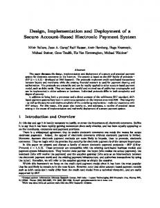
The Globe unified application model is based on distributed shared objects (DSOs). A Globe DSO encapsulates the data (state) of an application and the methods for manipulating it. As shown in Figure 2.1, a Globe DSO consists of a number of local objects (also known as local representatives), each residing in its own physical address space. A user process can access a Globe DSO by invoking the object’s public methods (which are exported in a number of public interfaces) on a local representative in its own address space. Depending on the particular DSO implementation, when an object method is invoked, the execution may be entirely local, or it may involve the local object interacting with other local objects part of the DSO; regardless of what happens, any interactions among local representatives are hidden from user processes by the Globe middleware layer. A1
A2 Address space
Distributed object Network Local Object A4
A3 A5
Figure 2.1: A Globe DSO replicated across four address spaces
By encapsulating application state inside objects, Globe achieves separation between interfaces and implementation. Essentially, as long as a DSO’s public interfaces are not modified, its implementation can be changed without affecting user processes. Furthermore, this also leads to cross-platform compatibility; by writing object interfaces in a high-level, platform-independent language, it
2.2. THE INTERNAL STRUCTURE OF A GLOBE LOCAL OBJECT 13 is possible to have local representatives of the same DSO hosted on different computing platforms. However, this heterogeneous DSO structure is invisible to user processes, which only have to deal with the platform-independent DSO interfaces. Finally, Globe achieves world-wide scalability through object replication. Replication is implicit in the Globe object model; essentially, each local object part of a DSO can be seen as replicating some part of the DSO’s state and functionality. The Globe middleware provides individual DSOs with mechanisms for dynamically instantiating new local representatives in order to handle increased load (improve scalability), or compensate for local objects that may be temporarily unavailable due to network or host problems (improve fault-tolerance). Furthermore, Globe allows individual DSOs to control of all their implementation aspects, including the functional (application-specific), but also extrafunctional ones. Typical extra-functional aspects include mechanisms used by local objects to communicate with each other, mechanisms for ensuring state consistency among local objects, or the mechanisms for enforcing a global DSO security policy across all its local representatives. As a result, each DSO can select the communication protocols, replication algorithm, and security model that are best suited to its needs. By not mandating a “one-size-fits-all” approach to handle extra-functional implementation aspects, Globe can support a wide variety of application types, which is the key to ensuring world-wide scalability.
2.2
The Internal Structure of a Globe Local Object
One goal of the Globe middleware is to facilitate re-usable design, and this has influenced the way Globe local objects are organized. Essentially, Globe requires that local objects follow a modular structure, consisting of a number of subobjects separated through standard interfaces. Each subobject implements one particular aspect of the object’s extended functionality (in this extended functionality we also include the extra-functional aspects of the object’s implementation, such as support for replication or security). Because subobjects are standardized, application developers can re-use the same subobject implementation for an entire class of applications that share some common extended functionality. In this way, only subobjects that implement application-specific functions have to be rewritten. Figure 2.2 shows the internal structure of a Globe local object. Each subobject implements one particular aspect of the DSO’s extended functionality as follows: • The semantics subobject implements the actual application functionality, and (logically) holds the application state. In many cases, this is the only subobject that the application developer has to actually code. Given the separation of functions introduced by the modular structure of the Globe local object, all extra-functional aspects of the DSO implementation, such as network communication, replication, and security should, in theory, be transparent to the semantics subobject. In practice, this may not be always possible, since in certain cases the distributed nature of a
14
CHAPTER 2. OVERVIEW OF THE GLOBE MIDDLEWARE Client Process
Local object
App-specific
Control sub-object
replCB
semState
repl
Replication sub-object
App-specific
Semantics sub-object
commCB
secRepl secComm
comm
Communication sub-object
App-security
Security sub-object
Network Figure 2.2: The internal structure of a local object. Round-corner rectangles indicate subobjects. Square boxes indicate interfaces. Standard interfaces are drawn in solid lines. Dashed lines indicate interfaces that need to be defined by the developer. Dotted lines indicate security-related interfaces, not defined in the original Globe design. Arrows indicate possible interactions among component subobjects.
DSO will affect the application semantics. For example real-time applications need to be aware of the fact that communication over wide-area networks may be unreliable and may introduce high latencies. Also, as we will discuss in the next chapter, in some cases security issues are integral part of the application semantics, so the semantics subobject will have to implement and enforce at least part of the DSO’s security policy. • The replication subobject manages all aspects related to the DSO’s replication policy; this includes keeping the state of local objects consistent (according to the DSO’s consistency model), and dispatching method invocation requests for local or remote execution. In order accomplish this, replication subobjects on different local representatives of the same DSO communicate using a DSO-specific replication protocol. Different local representatives of the same DSO may contain different replication subobjects, each implementing a different role in the replication protocol (for example master and slave subobjects, in the case of the Master-Slave replication protocol). • The communication subobject takes care of all communication between local objects part of the same DSO, and provides a standard interface for sending and receiving messages. The communication subobject
2.2. THE INTERNAL STRUCTURE OF A GLOBE LOCAL OBJECT 15 implements the communication model required by a given DSO; this may involve either reliable or un-reliable network communication, inter-process communication (for local representatives running on the the same host), point-to-point or group communication primitives, and so on. • The security subobject is responsible for enforcing the global DSO security policy on each local representatives part of it. This subobject is an example of a “security hook” included in the original Globe design for supporting future security extensions. The security subobject is intended to act as a reference monitor, essentially mediating any security-sensitive action performed by other subobjects against the global DSO security policy. • The control subobject accepts method invocations from client processes, and controls the interaction between the semantics and replication subobjects. This subobject is needed in order to bridge the gap between the programmer-defined interfaces of the semantics subobject and the standard interface of the replication subobject. For example, the semantics subobject marshalls and unmarshalls method invocations and replies. In general, the control subobject is generated using a stub compiler. Not all globe local objects need to implement all the subobjects described so far. The typical situation is that the semantics subobject is implemented by a subset of all local objects of a given DSO; these local objects are the DSO’s replicas and collaborate to implement the functionality of the application modeled by that given DSO. Essentially, their task is to accept user requests, execute them, return the results, and possibly propagate state changes (due to specific requests) to other replicas. Users interact with replicas through user proxies, these are smaller, “stripped-down” local objects running in the user address space. Normally, user proxies do not incorporate the DSO’s semantics subobject, and do not hold the DSO’s state; instead, they simply forward the user method invocations to a replica that can execute them.
2.2.1
Interaction among subobjects
Subobjects part of a local representative interact through functional interfaces, as shown in Figure 2.2. Some of these interfaces are defined by application developers, but most of them are standardized in order to facilitate re-usable subobjects. For the rest of this thesis we will use the interfaceName::methodName() syntax to indicate a call to method methodName of interface interfaceName. The application interface In order to provide access to the application functionality, the semantics subobject exports an application-specific interface (see Figure 2.2). This is a nonstandard interface, and needs to be defined by the application developer (we will show how this is done in Section 2.4.1). To allow user processes to invoke the DSO’s methods, the control subobject exports the same application interface as the semantics subobject. For each request there are two possible courses of action: the request can be handled locally (by the semantics subobject) or it can be dispatched to one of the other
16
CHAPTER 2. OVERVIEW OF THE GLOBE MIDDLEWARE
local representatives as a remote method invocation. The replication subobject is responsible for making this decision, according to the DSO’s replication protocol. For example, for Master-Slave replication, slave replicas can locally execute read requests, but write requests need to be shipped to the master. The method invocation state machine In order to keep track of the way user requests are handled, the control and replication subobjects follow the state machine shown in Figure 2.4. When a DSO method is invoked, the control subobject is in the START state. The control subobject then calls repl::start() on the repl standard interface (see Figure 2.3) of the replication subobject, passing a numeric Id corresponding to the application-specific method being invoked. The mapping between the names of the methods part of the application-specific interface and the numeric IDs used by the replication subobject is generated by the stub compiler used to create the control subobject. enum action_t {SEND, INVOKE, RETURN}; interface repl{ /* start ivocation start machine */ action_t start(in uint16 methodId); /* send request to remote replica */ action_t send(in uint16 methodId, in sequence marshalledRequest, out sequence marshalledReply); /* indicate successful local invocation */ action_t invoked(in uint16 methodId); }; Figure 2.3: The repl standard interface. For simplicity, initialization functions and error parameters have been omitted
According to the replication protocol used, the replication subobject returns either INVOKE or SEND on the repl::start() call. INVOKE specifies that the method should be executed locally, so the control subobject first invokes the appropriate method on the application-specific interface of the semantics subobject and then calls repl::invoked() on the replication subobject to indicate the execution has completed. On the other hand, SEND specifies the method needs to be executed remotely; in this case, the control subobject marshalls the method name and parameters and passes them to the replication subobject by calling repl::send(). Finally, the RETURN return value (for either repl::invoked() or repl::send()) indicates to the control subobject that it can return the result of the method invocation to the calling process. Handling remote method invocations The replication subobject is responsible for dispatching remote invocation requests and keeping the DSO state consistent. Marshalled requests are received from the control subobject (via the repl::send() call). The replication subobject
2.2. THE INTERNAL STRUCTURE OF A GLOBE LOCAL OBJECT 17 start() A
INVOKE
C C
C
start() B
invoked()
C
send() START
A C
SEND
RETURN invoked()
C B
send()
Figure 2.4: The state machine controlling method invocation. The A execution flow corresponds to local method invocation, B corresponds to remote method invocation, and C corresponds to active replication (local and remote method invocation).
dispatches them to a remote replica via the communication subobject, by calling comm:send() on the comm interface of the communication subobject (see Figure 2.5). After the request has been sent, the replication subobject blocks the client process, until it receives the result. interface comm{ /* connect to another LR */ void connect(out uint16 connId, in sequence contactPoint); /* send a message to another LR */ void send(in uint16 connId, in sequence msg); /* listen for incoming connections */ void listen(in sequence contactPoint); /* close a connection */ void close(in uint16 connId); }; Figure 2.5: The comm standard interface. For simplicity, error parameters have been omitted
On the remote replica, the communication subobject creates a pop-up thread for each request packet received from the network. This thread is responsible for carrying out the method execution. First the request packet is passed to the replication subobject via a commCB::msgArrived() call on the commCB standard interface of the replication subobject (see Figure 2.6). The replication subobject forwards the request to the control subobject by calling replCB::handleRequest() on the replCB standard interface (see Figure 2.7). In turn, the control subobject unmarshalls the request, and invokes the appropriate method on the application specific interface of the semantics subobject (for more details on remote method invocation see Section 2.3.3). Handling state updates Methods that change the DSO state need to be executed sequentially. The replication subobject keeps a lock that ensures that only one process/thread at a time can invoke write methods on the semantics subobject. When the DSO state is modified, the replication subobject is also responsible for propagating the changes to other replicas. State updates that occur simultaneously at different replicas are handled according to the DSO’s state consistency model, which
18
CHAPTER 2. OVERVIEW OF THE GLOBE MIDDLEWARE
interface commCB{ /* a message has arrived on one of the open connections */ void msgArrived(in uint16 connId, in sequence replProtMessage, out sequence replProtReplyMessage); }; Figure 2.6: The commCB standard interface. omitted
For simplicity, error parameters have been
interface replCB{ /* pass a marshalled request to the control subobject */ void handleRequest(in sequence marshalledRequest, out sequence marshalledReply); /* request the marshalled LR state from the control subobject */ void getState(out sequence marshalledState); /* pass the marshalled state to the control subobject */ void setState(in sequence marshalledState); }; Figure 2.7: The replCB standard interface. For simplicity, error parameters have been omitted
is implemented by the replication subobject. Depending on this model, DSO replicas may have to engagge in complex negotiation before accepting write requests (for example in the case of a total order consistency model). The replication subobject can request the local state by calling replCB::getState() on the control subobject. The control subobject in turn obtains the state from the semantics subobject by calling semState::getState() on the semState standard interface (see Figure 2.8). When a state update is received from the network, the communication subobject passes it to the replication subobject via a commCB::msgArrived() call. The updated state is further propagated to the control subobject via a replCB::setState() call, and finally to the semantics subobject via a semState::setState() call (for more details about state updates see Section 2.3.3). interface semState{ /* get the LR state from the semantics subobject */ void getState(out sequence marshalledState); /* update the LR state on the semantics subobject */ void setState(in sequence marshalledState); }; Figure 2.8: The semState standard interface. omitted
For simplicity, error parameters have been
Security subobject interfaces Because security was not covered in the original Globe design, no interfaces are defined for the security subobject. A preliminary security design evalua-
2.3. THE GLOBE OPERATIONAL MODEL— USER’S PERSPECTIVE 19 tion [128] suggests providing two additional security interfaces—secComm and secRepl—for interaction with the communication and replication subobjects. The assumption was that the sec-comm interface would be used for link encryption and authenticating network connections to the local object, while the repl-comm interface will be used for enforcing access control on DSO method invocation. Furthermore, the security subobject may also need to support a non-standard (programmer-defined) interface for interacting with the semantics subobject, in order to deal with application-specific security mechanisms.
2.3
The Globe Operational Model— User’s Perspective
So far we have described the Globe uniform distributed object model and the way Globe local objects are internally organized. At this point, it is time to explain how Globe DSOs are actually deployed and used. In this section we examine this problem from the DSO users’ point of view. Before a client process can interact with a Globe DSO, a user proxy for the object needs to be instantiated in the client’s address space, and connected to one of the DSO’s replicas. This process is known as binding to a DSO. Once a client is bound to a DSO, it can interact with it through method invocation on the local proxy. The proxy passes method invocation requests to the replica to which it is bound, and returns the results to the client process. Before describing object binding and method invocation in detail, we first discuss the way naming and locating objects are handled in Globe.
2.3.1
Object naming and location
Each Globe DSO is identified by a 128 bit object ID (OID). Object IDs are globally unique and location-independent. However, dealing with such long bit strings is not a human-friendly solution; to improve usability, Globe allows objects to be also identified through symbolic (human-readable) names. The mapping between object names and OIDs is done by the Globe Name Service (GNS). The GNS is a distributed service, and has been designed following the same principles behind the Domain Name Sevice (DNS) [161], so it can potentially scale to handle billions of objects. Furthermore, using the GNS for the binding process is not mandatory; individual DSOs may use it for convenience, but they can also implement their own naming infrastructure should this be more appropriate. For DSOs serving closed communities (for example e-banking applications) an alternative could be to distribute OIDs to users by out-of-band mechanisms (e.g. on a CD-ROM “snail-mailed” to customers); another alternative would be to incorporate OIDs in a hyper-linked structure (in the case of DSOs modeling Web documents, as described in [181]). OID
Implementation Identifier
Figure 2.9: The Structure of a replica contact address
Replica Properties
20
CHAPTER 2. OVERVIEW OF THE GLOBE MIDDLEWARE
OIDs are useful for uniquely identifying a Globe DSO, but, since they are location-independent, they cannot be used to locate the DSO’s individual replicas. This process requires an additional mapping, and is facilitated by another middleware service—the Globe Location Service (GLS) [45]. For a given DSO, the GLS maps the OID to a set of contact addresses corresponding to the object’s replicas. A contact address is just a long bit string; its structure is shown in Figure 2.9. The contact point part of the contact address specifies where a DSO replica can be contacted; it is basically the replica’s network address. The implementation identifier part of the contact address specifies how the replica should be contacted; this describes the complete protocol stack that needs to be implemented on the client side in order to interact with the DSO. Essentially, the implementation identifier is a high-level description (in terms of component subobjects) of the user proxy that needs to be instantiated. Finally, the replica properties part of the contact address describes the role a given replica plays in the overall DSO functioning. For example, a DSO using a master-slave replication protocol will have Master and Slave replicas. Further differentiation of replicas can be based on their security properties, as described in the next chapter. GLS implementation details Since every client process needs to query the location service before binding to a DSO, the GLS presents a potential scalability and performance bottleneck. To overcome this problem, the GLS is implemented as a distributed search tree, as shown in Figure 2.10. In this tree, the world is divided into a hierarchical set of domains. At the lowest level, there is a domain per site; a collection of sites form a region, and so on. An object is recorded at each site where it has a contact address, pointers to that node are then stored recursively in each enclosing region, up to the root of the tree. When a process performs a location look-up, the search starts with the node corresponding to the site where the process is located, and recursively progresses up the tree. Once a record is found, the look-up follows the pointers down to the tree leaf where the contact address is stored. In this way the look-up time is proportional to the distance between the originating site and the site where the replica is located. A potential problem with this design is that the root node, or in general, the higher-level nodes in the hierarchy, have to store lots of forwarding pointers, and handle lots of requests, so they are a potential scalability bottleneck. The GLS overcomes this problem by partitioning each directory node into multiple subnodes. Each subnode is made responsible for a specific part of the OID space via a special hashing technique. More details about the design, implementation and performance of the location services can be found in [36, 45].
2.3.2
The binding process
The process of binding between a client and a Globe DSO is shown in Figure 2.11. The client process starts with a symbolic DSO name (step 1 Figure 2.11). The Globe run-time contacts the GNS and resolves the symbolic name into the DSO’s OID (step 2). The OID is then passed to the GLS, which returns a set of
2.3. THE GLOBE OPERATIONAL MODEL— USER’S PERSPECTIVE 21
World
Europe
Holland
Utrecht Utrecht Domain Holland Domain Europe Domain World Domain Figure 2.10: The hierarchical structure of the Globe Location Sevice
Client Host
Replica Host
User Proxy Con.
Replica 6. bind
Rep. Com.
Sec.
Con. Rep.
Sem.
Com.
Sec.
5. instantiate proxy
7. invoke method
Globe Runtime
4. retrieve class objects
3. location lookup
Repository
GLS
Client process 1. Client DSO name lookup
2. name lookup
GNS
Figure 2.11: Binding to a Globe DSO. Arrows indicate actions. Replies to these actions are implicit.
contact addresses corresponding to the DSO’s replicas (step 3). The client runtime selects one of these addresses (based on network proximity for example); it then uses the implementation identifier part of the address to create the user proxy. The implementation identifier specifies the individual subobjects (see Section 2.2) that need to be instantiated as part of the proxy. The Globe run-
22
CHAPTER 2. OVERVIEW OF THE GLOBE MIDDLEWARE
time retrieves the required class objects from an implementation repository (step 4), and combines them to create the user proxy (step 5). Once the user proxy is in place, the client process connects it to the selected replica, by invoking a special bind() (public) method provided by the replica (step 6); this completes the binding process. At this point, the client process can start interacting with the DSO by invoking methods in the DSO’s application interface (step 7). An essential part in the binding process is played by the Globe run-time. Essentially, this is a collection of library functions that perform the various steps in the binding process. For example, the run-time includes service resolvers (stubs) for contacting the GNS and the GLS; methods for loading object classes from the implementation repository, and for combining the object classes corresponding to the various subobjects in order to instantiate a DSO local representative. The Globe run-time is tied to a specific programming environment. For example, the Globe middleware prototype developed at the Vrije Universiteit is based on Java, so its run-time consists of a collection of Java libraries.
2.3.3
DSO method invocation
Once a user proxy has been instantiated in the client’s address space, the client process can start interacting with the object by invoking the methods exported part of the proxy’s public interfaces. Client Process I
IV
Control Sub-object
User Proxy
IV
Semantics Sub-object
Control Sub-object
II
Master Replica
Slave Replica
Semantics Sub-object
Control Sub-object
Security Subobject
Replication Sub-object
III I
I
IV
IV
Replication Sub-object IV
Security Subobject IV
Comm. Subobject
I
IV
II
III
Replication Sub-object II
II
Semantics Sub-object
III
III
Security Subobject
III Comm. Subobject
Comm. Subobject
IV
III
III
III
Network
Figure 2.12: DSO method invocation. The dashed subobjects are not implemented. The user proxy does not implement the semantics subobject. In the original Globe design the security subobject acts as a “hook” for future security extensions, and it is not implemented by any of the local objects. Arrows indicate the control flow for the four phases of the method invocation process.
Figure 2.12 shows the control flow during a method invocation on an DSO implementing a Master-Slave replication strategy. Logically, the method invocation process can be divided in four distinct phases: • Phase 1—the client proxy propagates the method request to the master replica. • Phase 2—the master replica executes the request. • Phase 3—the master replica propagates state changes to slave replicas. • Phase 4—results are returned to the client. We will discuss each of these phases in detail.
2.3. THE GLOBE OPERATIONAL MODEL— USER’S PERSPECTIVE 23 Phase 1 Figure 2.13 shows the control flow during the first phase of the method invocation process. We assume the application-specific interface exported by the DSO is called appSpecific, and the client invokes a method m part of it. We make use of the standard interface specifications introduced in Section 2.2.1. There are five distinct steps: Client Host Client process
1
User proxy
appSpecific
Control sub-object replCB 2
3 repl
Replication sub-object commCB 4
comm
Communication sub-object
Security sub-object
5
Network Figure 2.13: Phase 1 of DSO method invocation
1. The client process invokes appSpecific::m() on the control subobject in the proxy. 2. At this point the control subobject is in the START state on the method invocation state machine (see Section 2.2.1). Accordingly, the control subobject invokes repl::start(methodId(m)) on the replication subobject. Here methodId(m) denotes the method ID assigned to method m of the appSpecific interface (see Section 2.2.1). 3. Because m cannot be execute locally (the proxy has no semantics subobject), the replication subobject returns SEND. The control subobject moves to the SEND state, marshalls the method name and parameters, and passes them to the replication subobject by calling repl::send().
24
CHAPTER 2. OVERVIEW OF THE GLOBE MIDDLEWARE 4. The replication subobject incorporates the marshalled request into a replication protocol-specific request message and passes it to the communication subobject by calling comm::msgSend(). 5. The communication subobject encapsulates the request message into a network packet and sends it to the peer communication subobject of the master replica. The comm::msgSend() call successfully returns in the replication subobject. At this point, the client process is blocked (on the repl::send() call inside the replication subobject) waiting for the result of the method invocation.
Phase 2 Figure 2.14 shows the control flow once the master replica has received the invocation request from the proxy. There are four distinct steps: Master Replica Host
Master Replica
appSpecific
Control sub-object 9
replCB 8 repl
semState
Replication sub-object
appSpecific
Semantics sub-object
commCB
7 comm
Communication sub-object
Security sub-object
Network pop-up thread 6
Network Figure 2.14: Phase 2 of DSO method invocation
6. When the network packet is received by the master replica host, the Globe run-time creates a pop-up thread which passes the packet to the communication subobject for processing.
2.3. THE GLOBE OPERATIONAL MODEL— USER’S PERSPECTIVE 25 7. The communication subobject extracts the request message from the network packet, and forwards this message to the replication subobject by calling commCB::msgArrived(). 8. The replication subobject determines that the request can be served locally (because the master replica implements the DSO’s semantics subobject), so it extracts the marshalled request from the request message and passes it to the control subobject by calling replCB::handleRequest(). 9. The control subobject un-marshalls the request and invokes the appropriate method (m in this case) on the semantics subobject by calling appSpecific::m(). Phase 3 In the third phase of the method invocation process, the master needs to propagate state changes to slave replicas. Figure 2.15 shows the control flow. There are eight distinct steps: Master Replica Host
Master Replica
Slave Replica Host
Slave Replica
appSpecific
appSpecific
Control sub-object
Control sub-object
replCB
replCB
17
11 16 10
repl
semState
appSpecific
Semantics sub-object
Replication sub-object
repl
semState
commCB
appSpecific
Semantics sub-object
Replication sub-object commCB
12 15 comm
Communication sub-object
13
comm
Security sub-object
Communication sub-object
Network pop-up thread
Security sub-object
Network pop-up thread 14
Network Figure 2.15: Phase 3 of DSO method invocation
10. Once the request has been executed on the master (that is, when the call replCB::handleRequest() in step 8 has returned successfully), the replication subobject determines that the method invocation has changed the
26
CHAPTER 2. OVERVIEW OF THE GLOBE MIDDLEWARE local state. As discussed in Section 2.2.1, the replication subobject has a mapping specifying which methods (method IDs) change the DSO state. As a result, the replication subobject requests the (updated) state by calling replCB::getState() on the control subobject.
11. The control subobject requests the (marshalled) local state from the semantics subobject, by calling semState::getState(), and returns it to the replication subobject. 12. The replication subobject incorporates the marshalled state into a replication protocol-specific message and passes it to the communication subobject by calling comm::msgSend(). 13. The communication subobject encapsulates the replication message into a network packet and sends it to the peer communication subobject of the slave replica. 14. When the network packet is received by the slave replica host, the Globe run-time creates a pop-up thread which passes the packet to the communication subobject for processing. 15. The communication subobject extracts the replication message from the network packet, and passes it to the replication subobject by calling commCB::msgArrived(). 16. The replication subobject determines that the message is a state update request, so it extracts the marshalled state, and passes it to the control subobject by calling replCB::setState(). 17. The control subobject updates the state of the semantics subobject by calling semState::setState(). Phase 4 Finally, the master replica needs to return the result of the method invocation to the proxy. Figure 2.16 shows the control flow. There are seven distinct steps: 18. The replication subobject on the master receives the (marshalled) result from the control subobject as return value from the replCB::handleRequest() call in step 8. 19. The replication subobject incorporates the marshalled result into a replication protocol-specific message and passes it to the communication subobject as a result of the commCB::msgArrived() call in step 7. 20. The communication subobject encapsulates the replication message into a network packet and sends it to the peer communication subobject on the proxy. The network pop-up thread on the master replica host terminates. 21. The communication subobject on the proxy receives the network packet sent by the peer subobject on the master. 22. The communication subobject extracts the replication message from the network packet, and passes it to the replication subobject by calling commCB::msgArrived().
2.4. THE GLOBE OPERATIONAL MODEL—DEVELOPER’S PERSPECTIVE27 Client Replica Host Client process
Master Replica Host
24
User Proxy
Master Replica
appSpecific
appSpecific
Control sub-object
Control sub-object replCB
replCB
23 18 repl
repl
Replication sub-object
Replication sub-object
commCB
semState
appSpecific
Semantics sub-object
commCB
19
22 comm
comm
Communication sub-object
21
Security sub-object
Communication sub-object
Network pop-up thread
Security sub-object
Network pop-up thread 20
Network Figure 2.16: Phase 4 of DSO method invocation
23. The replication subobject determines that the message is the result of a (previous) method invocation, it extracts the marshalled result, and returns it as a parameter of the repl::send() call from step 3. This un-blocks the client process. The return value for repl::send() is set to RETURN. This indicates the control subobject that it should return the result to the client process. 24. The control subobject un-marshalls the result, and returns it to the client process as a result of the appSpecific::m() call from step 1. It is important to note that the security subobject is not involved in any of these steps, because no security mechanisms are part of the original Globe design. In the next chapter we will show how to secure the method invocation process.
2.4
The Globe Operational Model— Developer’s Perspective
In the previous section we have discussed the Globe operational model from a user’s point of view. However, before a DSO can be used, it needs to be implemented (coded), created and deployed. In this section we address these
28
CHAPTER 2. OVERVIEW OF THE GLOBE MIDDLEWARE
issues, looking at the Globe middleware from an application developer’s point of view.
2.4.1
The Globe programming model
The first phase in the lifetime of a Globe distributed application is the design. This includes the functional design (this concerns what the application should actually do), but also the design of the extra-functional aspects of the application, such as the required replication strategy, communication protocols and security model. Essentially, this design process closely follows the internal structure of a Globe local object described in Section 2.2; once the design is complete, the application developer has a clear idea of the types of subobjects required for the implementation. Depending on the types of subobjects required, the developer can either re-use class objects already implemented (possibly from public class repositories), or he may have to code the classes for some of these objects himself. The developer will most likely have to code the semantics subobject (or at least a significant portion of it). On the other hand, since there are only a limited number of communication protocols commonly used, it is likely that the communication subobject can be instantiated by re-using a library class. The same applies, although to a lesser extent, for the replication and security subobjects. The control subobject is automatically generated from the application interface by a stub compiler. As discussed in Section 2.2.1, each Globe subobject exports a number of programming interfaces for interacting with other subobjects. Most of these interfaces are standardized, but some of them are application-specific, so the developer has to actually define them. The Globe middleware provides an Interface Definition/Description Language (IDL) [182] for specifying object interfaces. The Globe IDL is a high-level, platform-independent language mainly supporting constant, type, and function declarations. Given an IDL interface, an IDL compiler will map the interface to a target programming language, creating skeleton implementations (stubs) of the interface’s methods. The developer then needs to extend these stubs to implement the required (sub)-object functionality. Once this is done, the resulting source code is compiled (using a compiler for the target language), in order to produce object code (classes). Once the application developer has classes for all required subobjects, he can create the new DSO, by selecting the hosts where the DSO’s replicas need to be placed, and then instantiating replicas on these hosts.
2.4.2
The Globe object server
Globe local objects (user proxies and replicas) are static. In the case of user proxies, these are instantiated by the Globe run-time as a result of a user process (thread) binding to a DSO. However, object replicas may not always have an execution process/thread associated with. Typically, a DSO replica waits until it receives a remote method invocation from a proxy, executes the method, propagates potential state changes to other replicas, and returns the result to the proxy. All this replica activity is initiated by network pop-up threads (see Section 2.3.3) controlled by a special middleware service called the Globe Object Server (GOS).
2.4. THE GLOBE OPERATIONAL MODEL—DEVELOPER’S PERSPECTIVE29 The GOS provides an execution environment for remote method invocations on DSO replicas. For each hosted replica, the GOS is responsible for managing the network contact points where other DSO local representatives (either user proxies or other replicas) bind to that replica. The GOS maintains a pool of active threads; whenever a network packet is received on one of the managed contact points, the GOS dispatches one of these threads to handle the request. The dispatched thread controls the execution flow for processing the request, as described in Section 2.3.3. Besides managing contact points, the GOS provides a number of other services which can be accessed through standard interfaces. The server manager allows for replica creation, management and destruction, and accepts RPCs from remote processes that want to place replicas on the GOS. The persistence manager provides an operating-system independent interface to persistent storage. Replicas can use this service to store their state on the host machine. This allows for example replicas to survive graceful shutdown and restart of the GOS hosting them.
2.4.3
Object creation
Once an application has been implemented as a Globe distributed object, the party in charge of its deployment (the DSO administrator) needs to actually create the DSO. This involves the following steps: • generating a unique OID for the new DSO. • possibly registering the DSO name and OID with the GNS. • selecting a GOS for placing the first DSO replica. • creating a contact address for that replica and registering it with the GLS. • instantiating the new replica on the selected GOS. The initial Globe design does not specify how a unique OIDs are to be generated; this may either involve contacting a global object registration authority, or partitioning the OID space among different DSO administration authorities. As we will show in the next chapter, it is actually possible to generate (statistically) unique OIDs in a completely de-centralized manner, by using certain properties of RSA public keys and of secure hash functions. Once the new DSO has a unique OID, the administrator may register it with the GNS, or may use alternative naming infrastructures, as discussed in Section 2.3.1. At this point, the administrator selects a GOS for hosting the first replica of the new DSO. The administrator contacts the GOS on the management interface and requests permission to instantiate a new replica. The GOS allocates a network contact point for the new replica; the administrator uses this contact point to generate a contact address for the replica, which is then registered with the GLS. The administrator then passes the contact address and the location of the implementation repository to the GOS. Using the protocol identifier in the contact address (which fully describes the replica in terms of component subobjects) the GOS retrieves all the necessary classes from the repository and uses them to instantiate the new replica.
30
2.4.4
CHAPTER 2. OVERVIEW OF THE GLOBE MIDDLEWARE
Object deployment
A DSO is created by instantiating its first replica. In the DSO deployment phase, other replicas of that object are instantiated according to the object’s needs. As discussed in Section 2.1, a DSO may be replicated for scalability and/or fault-tolerance reasons. Each DSO is allowed to select its own policy for instantiating new replicas. On one end, this process can be entirely manual—the DSO administrator decides on the number of replicas required, selects the object servers where these replicas need to be placed, and contacts each of the servers to instantiate the replicas. On the other hand, the full power of the Globe DSO model can harnessed by using a dynamic replication protocol (implemented by the replication subobject). In this case, the DSO is responsible for automatically instantiating new replicas in order to handle increased load (e.g flash crowds), or the (temporary) failure of existing replicas (e.g. due to host or network problems). It is also possible to have a hybrid replication model, with a subset (the core group) of the DSO’s replicas manually created by the administrator, and the rest being dynamically instantiated by members of the core group. Regardless of the replication model employed, the DSO administrator (in the case of manual replication) or the replicas (in the case of dynamic replication) need a way to find Globe object servers that can host new replicas. To facilitate the server discovery process, Globe provides another middleware service—the Globe Infrastructure Discovery Service (GIDS).
2.4.5
The Globe infrastructure discovery service
The GIDS (described in detail in [123]) keeps track of all the object servers available worldwide. Its implementation uses the Light-weight Directory Access Protocol (LDAP) and standard LDAP servers [131]. Similar to the GLS, the GIDS is a distributed service. Essentially the world is divided into a set of base regions (generally subdivisions of the leaf domains identified for the GLS); in each base region there is a GIDS server that keeps track of all available object servers in that region. The GIDS allows discovery of suitable object servers based on a specification of desired properties, related to technical capabilities (amount of memory, available bandwidth, operating system and hardware platform), security attributes (which person or organization operates this object server), and the location of the object server. When a DSO entity (administrator, replica) needs to instantiate a new replica, it queries the GIDS with a set of desired properties. Some of these properties may be derived from the DSO implementation and functionality (e.g. the operating systems/hardware paltforms supported by the object code, the memory/CPU requirements), others may depend on the specific replication scenario (e.g. network placement of a new replica, so that overall request latency is minimized), while others may depend on the DSO’s security policy (e.g. which administrative domains are trusted to host the DSO’s replicas). Once a matching server is found, the entity creating a new replica and the selected GOS enter a negotiation phase to determine whether or not they want and can cooperate, and negotiate the exact details of that cooperation.
Chapter 3
Security Requirements In this chapter we present the set of requirements that have guided the design and implementation of the Globe security architecture. The first step in identifying these requirements is determining the specific threats the Globe security architecture needs to counter. However, defining a threat model for a system like Globe is difficult for the following reasons: • Lack of a central trust authority. Globe has been designed to support millions of users and billions of objects, and it is simply un-realistic to assume a central trust authority in such an environment. A central trust authority for Globe would not work for the same reasons it cannot work for the Internet as a whole. First, such a central authority would not scale. Second, it is practically impossible to find an organization that is perceived as impartial by millions of people of different nationalities and religions, spread across five continents, many having contradictory political and economic agendas. • Broad applications space. Globe is a middleware platform, and is intended to support a large variety of distributed applications. It is impossible to come up with a generic security architecture supporting all requirements for every potential Globe application. A more realistic approach is to identify a set of pervasive security requirements (common to large number of possible Globe applications); mechanisms to address these requirements can then be provided as core middleware security services; individual Globe applications can then extend this core by adding more specialized security features. • Applications spanning multiple administrative domains. As discussed in Chapter 2, the purpose of the Globe middleware is to allow seamless development and deployment of distributed applications, with emphasis on application replication (for scalability, or fault tolerance reasons) and code re-use. Globe object replicas may be placed on servers belonging to different administrative domains, and may be instantiated by combining object code from different developer communities. This makes it particularly difficult to define a trusted computing base (TCB). The rest of this chapter is organized as follows: in Section 3.1 we look at what “security” actually means, and we define it in terms of three system properties: 31
32
CHAPTER 3. SECURITY REQUIREMENTS
confidentiality, integrity and availability. In Section 3.2 we define a number of basic security terms, to be used throughout the rest of the thesis. In Section 3.3 we start exploring the requirements space for the Globe security architecture by identifying four classes of security principals with distinct security agendas, which are involved in the operation of the Globe middleware: Globe users, DSO administrators, GOS administrators, and Globe developers. In Section 3.4 we look at security requirements from the users’ point of view. In Section 3.5 we look at security requirements from the DSO administrators’ point of view. In Section 3.6 we look at security requirements from the GOS administrators’ point of view. In Section 3.7 we look at security requirements from the Globe developers’ point of view. Finally, in Section 3.8 we put pieces together by grouping security requirements into five categories: trust management, authentication and secure channel establishment, access control, Byzantine fault tolerance, and platform security. In subsequent chapters of this thesis we focus on specific security mechanisms for addressing each of these requirements.
3.1
What is Security?
Before examining any security requirements for Globe, it may be useful to define the concept of “security”. To date, the subject of computer security has generated substantial amount of research interest. However, it is surprisingly hard to find a generally-accepted definition of computer security; possible interpretations (in the chronological order of their appearance) include: “... a general term for all the mechanisms that control the access of a program to other things in the system” (1971—Butler Lampson [125]). “Security is the practice by which individuals and organizations protect their physical and intellectual property from all forms of attack and pillage.” (1997— Java security whitepaper [93]). “Computer security deals with the prevention and detection of unauthorized actions by users of a computer system.” (1999—Dieter Gollman [101]). “Computer security is the effort to create a secure computing platform, designed so that agents (users or programs) can only perform actions that have been allowed.” (2006—Wikipedia). Most of the definitions we found in the literature (including the ones abovementioned) are either too abstract, or too informal to provide a useful starting point for exploring security requirements for a system like Globe. Because of this, we will focus on a more functional statement about computer security, although technically, it does not qualify as a definition: “Computer security consists of maintaining three characteristics: confidentiality, integrity, and availability.” (excerpt from [165]; also appears in more or less same form in [54]). • Confidentiality means that resources of a computing system are accessible only by authorized parties.
3.2. BASIC CONCEPTS
33
• Integrity means that resources can be modified only by authorized parties in authorized ways. • Availability means that resources are accessible to authorized parties. The above definition provides us with high-level goals for the Globe security architecture; essentially, we want this architecture to protect the confidentiality, integrity and availability of middleware resources. However, before examining each of these goals in detail, we need to introduce a number of basic security concepts.
3.2
Basic Concepts
In this section we define a number of security concepts, to be used throughout the rest of this thesis.
3.2.1
Principals, authentication, and access control
A principal is an real-world entity (human/organization) whose actions have some security implications on the functioning of the Globe middleware. A software representative is a software component of the Globe middleware that acts on behalf of a principal or on behalf of another software representative. A name is a symbolic represenation of an entity that can be used for the purposes of authentication and access control. Identification is the process of associating a name to a Globe entity. A global name is an name that has the same meaning (identitfies the same Globe entity) for all entities part of the Globe middleware. The OIDs introduced in the previous chapter are examples of global names—an OID uniquely identifies a DSO for all the other entities involved with the Globe middleware. In contrast, local names only have meaning to individual Globe entities. For example, a DSO may assign an identifier to each of its users; these user identifiers act as local names for users—they are only meaningful in the context of that DSO. Resources include both data and software/hardware system components. Each resource has an owner—a principal that has administrative control over that resource. As discussed in the previous section, owners’ high-level security goals are ensuring the confidentiality, integrity, and availability of the resources they own. We need to stress that these properties may have different meanings, depending the type of resources being protected: • Data resources: – Confidentiality means the data is disclosed only to authorized parties. – Integrity means data can be modified only by authorized parties in authorized ways. – Availability means that data is protected from destruction (erasure). • Software/hardware resources:
34
CHAPTER 3. SECURITY REQUIREMENTS – Confidentiality means that only authorized parties can use the protected resource. – Integrity means that that resources will perform the tasks they are expected to perform, in the expected way. – Availability means that authorized parties will not encounter unjustifiable delays when using resources (denial of service—DoS).
A right with respect to a resource is the ability to perform certain operations on that resource. Possible rights that can be associated with a resource depend on the resource type. For example, in the case of data, rights may include reading, modifying, and deleting it; in the case of objects, rights may include invoking methods, creating/deleting replicas, and so on. The owner of a resource has by definition all the rights that can be associated with that resource. The resource owner can grant some of these rights to other entities (principals or software representatives), including the right to further grant granted rights to other entities (delegation). Access control is the process of enforcing rights on protected resources; the idea is that an entity is allowed to perform an action on a protected resource only in the following circumstances: • the entity is the owner of the resource. • the entity has been granted the right to perform the action (either directly by the owner, or from some other entity, through delegation). A reference monitor is a software component that enforces access control on a protected resource. Client System
Server System 1. Action Request
Entity requesting action
Secure Comm. Channel
Reference Monitor
3. Perform Action
Protected Resource
2. Access Control Check Figure 3.1: The reference monitor
A reference monitor operates as shown in Figure 3.1. Essentially, it is only the reference monitor that can directly perform actions on a protected resource; messages encoding action requests from various Globe entities are passed to the monitor over some secure communication channel; the monitor performs (executes) these actions only if the requesting entity has the rights to perform them. It is important that the reference monitor is capable of identifying entities, so that only those that have been granted the appropriate rights can invoke specific actions. Authentication is the process of securely associating an action request to the identity of the entity that has issued the request. A secure communication channel between two entities A and B is a communication channel where both communication endpoints are authenticated. A secure communication channel must at least ensure the integrity, and optionally the confidentiality and availability of the data in transit:
3.2. BASIC CONCEPTS
35
• Channel integrity—a message received by A on the secure channel could only have been sent by B. A message sent by B that is modified while in transit, will not be accepted by A. • Channel confidentiality—a message sent by A on the secure channel can only be received by B. • Channel availability—a message sent by A is guaranteed to be received by B; furthermore, transmission delay (latency) is finite and predictable. Typically, authentication and secure communication channels are implemented by means of cryptography. However, it is also possible to have physically secure communication channels; for example, a local area network with controlled entry points would qualify for this. Once rights have been granted, and authentication mechanisms are in place, access control is relatively easy to implement; the hard part is to get to this point. Trust management is the decision process of assigning rights to principals and determining which mechanisms are secure and trustworthy enough to authenticate them. Probably the best way to explain trust management is to present possible application scenarios; we have identified three types of such scenarios: • Trust management based on direct (implicit) trust relationships—this is the case when authentication mechanisms and rights are assigned based on external (real-world) trust relationships. For example, in a company, the employees rights with respect to usage of various resources are dictated by the organizational and administrative policies in place for that company. Similarly, authentication mechanisms can be arranged off-line (for example a secure internal LAN would provide implicit authentication of communication end-points; alternatively, or a company-wide public key infrastructure could accomplish the same goal). • Trust management based on trusted third parties. In this case, entities that are interacting share some common trusted third party that can distribute cryptographic keys for authentication, and provide certification of entity properties. Rights can then be granted based on those certified properties. Global PKIs and certification authorities such as Verisign fall into this category. • Trust management based on entity interaction. In this case, an entity gains the trust of another entity as a result of its actions. An example of this is subscription based services: initially, a user is completely untrusted, but once it pays a subscription fee it is granted the appropriate rights.
3.2.2
Faults and protection
The concepts introduced in the previous section deal with “good” security properties: ensuring that sources of requests are properly identified, and that requests are served only for authorized parties. However, there is also a “dark” side of security—it needs to deal with malicious entities and code, and the threats they pose to the correct functioning of a system. In order to have a
36
CHAPTER 3. SECURITY REQUIREMENTS
comprehensive security architecture for Globe, we need to look at these issues as well. In this section we introduce the basic concepts of “black hat” security. Malware is a piece of software that subverts the correct functioning of a computing system. Examples of malware include spyware, viruses, worms, Trojans, and so on. Threats posed by malware include loss of confidentiality (Trojans that provide back-doors for unauthorized users), loss of integrity (viruses that subvert application functionality), and loss of availability (spyware that wastes computing resources). A piece of code is trusted (trusted code) if it is guaranteed not to include any malware. Alternatively, untrusted code may or may not include malware. In the context of Globe, there are many circumstances where untrusted code may be executed—when object servers run third-party object replicas, when users instantiate untrusted DSO proxies, and so on. It is therefore important that the Globe security architecture provides protection mechanisms against malware. Platform protection is a generic term for protection mechanisms against malware. Platform protection mechanisms can be classified into three broad categories: sandboxing, code authentication and proof carrying code. Sandboxing is a protection technique where untrusted code is executed in an isolated runtime environment (sandbox). Potential malware incorporated into untrusted code may be able to compromise resources inside the sandbox, but it cannot reach any resources outside it. Code authentication deals with mechanisms that allow to establish a secure association between a piece of code and a principal (either the party that has produced the code, or the party that vouches for its correctness). Code that can be authenticated to trusted parties is then implicitly trusted. Of course, there is the issue of establishing trust among principals (those that produce code and those that run it), but this is dealt through trust management techniques. The idea behind proof carrying code [153] is to have a logical proof of correctness associated with each piece of code. Before a piece of (untrusted) code is run, the associated proof is then (automatically) checked by a (trusted) prover application, and only programs that pass the check are allowed to execute. A fault is the incorrect functioning of a computing system. Faults may be unintentional (due to software bugs, or external factors, such as power loss) or intentional (due to malware, malicious users, and so on..). An intentional fault (due to malicious intent) is also known as a Byzantine fault. Byzantine fault tolerance deals with protection techniques employed in the context of complex distributed application. Such applications (Globe DSOs are prime examples) typically consist of large number of components that work together to implement some high-level functionality. A distributed application is Byzantine fault-tolerant if it can provide correct functionality despite some of its components exhibiting Byzantine fault behavior.
3.3
Examining Security Requirements
So far, we have defined security in terms of three high-level goals: ensuring the confidentiality, integrity and availability of protected resources. However, it is difficult to design a security architecture following directly from these goals, given that (as shown in the previous section) existing protection mechanisms
3.3. EXAMINING SECURITY REQUIREMENTS
37
target more concrete (and lower-level) security requirements. The next step is to examine how the high level goals of confidentiality, integrity, and availability translate into concrete security requirements for individual Globe resource owners, and which mechanisms are appropriate for dealing with these individual requirements. The security requirements of individual Globe resource owners may derive either from self-interest (a bank customer wants to ensure the integrity of his banking transactions), or they may be the result of legal/organizatorial policies of the administrative domain the principal belongs to (a bank may require two employees to sign high value transactions). As explained in the previous chapter, Globe applications typically span multiple administrative domains. As such, different classes of security principals (each with their own, often contradicting, security requirements) need to interact even just for the operation of individual Globe DSOs. Consider the following example: The Veterinary Science Department at Universiteit van Utrecht (UU) is experiencing increased workload on their Web site. The department decides that improved scalability can be achieved by modeling the site as a Globe DSO. The web-master in charge of the site identifies an appropriate DSO class package—globeDoc [181]—developed at the Computer Science Department at Vrije Universiteit (VU). Once the Globe DSO modeling the web site is created, the web master decides to place one master replica at UvA and a second (slave) replica on a Globe object server operated by the Massachusetts Institute of Technology (MIT). Clients accessing the web site from North America will be automatically redirected to the MIT replica. In this (simple) example, we can already identify four classes of security principals: (1) the web master at UU, (2) the Globe developers at VU, (3) the Globe object server administrator at MIT, and (4) the clients that access the site. Generalizing, we define four classes of security principals that are involved with the Globe middleware: • DSO administrators. For each Globe DSO, the administrator is responsible for creating and deploying the object. The administrator is in charge of setting the DSO’s security policy. • Globe developers. These are parties that implement (code) class packages used to instantiate Globe DSOs. In theory, each DSO administrator can implement all the classes needed for instantiating the object. However, given the modular structure of Globe objects, and the emphasis put on code re-use, it is likely that the vast majority of DSOs will be instantiated using (at least partially) code written by third parties. • GOS administrators. These are principals in charge of operating Globe object servers for hosting DSO replicas. Again, it is possible to have all replicas of a given DSO hosted by GOSes operated by the DSO administrator. However, the power of the Globe distributed object model is fully harnessed when DSOs are capable of (dynamically) creating new replicas at various network locations, according to the object’s replication needs (scalability and/or fault tolerance). As a result, it is likely that for a given DSO, at least a subset of its replicas will be hosted on GOSes operated by third parties.
38
CHAPTER 3. SECURITY REQUIREMENTS • DSO users. These are parties that interact with a given Globe DSO, by invoking its methods through user proxies running in their address space (see Chapter 2).
Having identified these four classes of security principals allows us to conduct a more systematic requirements analysis. Essentially, we take each individual class and examine their specific security requirements.
3.4
Threats and Security Requirements— Users’ Perspective
The resources owned by Globe users are the computing platforms from which they access Globe DSOs and the sensitive information they may disclose/acquire while interacting with those DSOs. With respect to the computing platform, potential threats are coming from the code used to instantiate the user proxy. As discussed in the previous chapter, users proxies are instantiated using object code retrieved from an implementation repository. We assume that object code retrieved from a local repository (residing on the same host as the user) is trusted. A local repository would include proxy code part of the Globe standard distribution package—essentially proxies for common Globe applications such as GlobeDoc [181], or the Globe Distribution Network [42]. However, when interacting with Globe DSOs that are not part of the standard distribution, users may need to download proxy code from remote repositories. This is untrusted code (as defined in Section 3.2). Thus, one of the security requirements for users is platform protection, that is, ensuring that untrusted proxy code retrieved from remote repositories cannot compromise the confidentiality, integrity, and availability of the user’s platform. Users are also interested in protecting their private information while interacting with Globe DSOs. Both data confidentiality and integrity needs to be taken into account: • Confidentiality—Globe DSOs may be used to implement e-banking and e-commerce applications, and may handle sensitive information such as customer data, passwords, or credit card numbers. Such information needs to be protected against unauthorized disclosure. Unauthorized disclosure can occur either as a result of interacting with an un-authorized object (for example a malicious DSO pretending to represent a legitimate bank), or as a result of data being intercepted by malicious parties while in transit to a legitimate destination. • Integrity—Globe DSOs may be used to implement information dissemination services, such as electronic newspapers, or stock quotes services. In this context, it is important to ensure the information integrity—that is guaranteeing that information comes from legitimate sources, and has not been tampered while in transit. In order to ensure data confidentiality and integrity, the first requirement is for trust management mechanisms. Essentially, human users do not implicitly trust abstract software entities such as Globe objects, but rather real-world
3.5. DSO ADMINISTRATORS’ PERSPECTIVE
39
entities such as banks, governments, or other users. Trust management mechanisms should allow DSO users to establish secure associations between a DSOs, viewed as abstract services, and the real world entities that offer these services. Trust management prevents users from disclosing confidential information, and accepting information used for sensitive decisions from un-authorized DSOs. However, the confidentiality and integrity of data can also be compromised while data is transfered over the network (between trusted parties). In order to prevent this, the Globe security architecture should provide mechanisms for the authentication of communication end-points (the user proxy and the DSO replica handling its requests) and for establishing secure communication channels for data transfer.
3.5
Threats and Security Requirements— DSO Administrators’ Perspective
Essentially, administrators are responsible for offering services (modeled as a Globe DSOs) to their users; their security goals are protecting the confidentiality, integrity and availability of these services. The confidentiality goal dictates that only authorized users should be able to access a DSO. This introduces three types of security requirements. Trust management mechanisms are needed in order to assign rights to users; these are method invocation rights, given that users can only interact with DSOs by invoking their methods. Once rights are assigned to users, access control mechanisms are needed in order to enforce these rights; because Globe objects are replicated, access control needs to be enforced on each replica through some form of reference monitor. As explained in Section 3.2, a reference monitor receives operation requests over an authenticated, secure communication channel, and executes them if the originating entity has the appropriate rights. Hence, Globe DSOs need to provide mechanisms for user authentication and secure channel establishment. The integrity goal dictates that only authorized parties should be allowed to modify a given DSO, and that a DSO should correctly implement its functionality. In order to prevent the un-authorized modification of a DSO, only valid replicas should be allowed to issue state updates; furthermore, only authorized parties should be allowed to add/delete replicas. Thus, a DSO needs to implement mechanisms for authenticating replicas and establishing secure communication channels between them. Furthermore, trust management mechanisms are needed in order to assign replica creation/destruction rights to relevant Globe principals. Ensuring that a Globe DSO correctly implements its functionality is difficult for two reasons. First, as discussed in Chapter 2, a Globe DSO may be (partially) created using untrusted object code written by third parties; in this context, there is the threat of malware incorporated in this untrusted code that may maliciously (and covertly) alter the DSO application semantics. This introduces the need for trust management mechanisms for foreign code. Mechanisms for accomplishing this include code authentication (securely associating foreign code to a trusted entity), or proof carrying code.
40
CHAPTER 3. SECURITY REQUIREMENTS
Replication is the second factor that makes it difficult to enforce DSO integrity. As described in Chapter 2 at least some of a DSO’s replicas may run on untrusted, third-party controlled GOSes. In this context, there is the threat of malicious GOS administrators “hijacking” replicas running on their domains; “hijacked” replicas may exhibit all sorts of Byzantine-faulty behavior, ranging from denial of service (slow response, or even lack of response to user requests) to active attacks, such as returning erroneous results, or corrupting the DSO state. In this context, it may be necessary to restrict DSO replicas rights (with respect to what methods a replica is allowed to execute), based on the trustworthiness of the GOS hosting it. Again, trust management mechanisms are needed for assigning replicas rights. Once rights have been assigned, reverse access control mechanisms are needed to enforce them—essentially ensuring that users only sent their method invocation requests to replicas trustworthy enough to handle them. Finally, the availability goal dictates that a DSO should be capable of providing correct and timely service despite some of its replicas exhibiting faulty (possibly Byzantine-faulty) behavior. As such, the Globe security architecture also needs to provide Byzantine fault tolerance mechanisms.
3.6
Threats and Security Requirements— GOS Administrators’ Perspective
As discussed in Chapter 2, Globe object servers can potentially host replicas of DSOs operated by third parties (not necessary trusted by the GOS administrators). As such, GOS administrators essentially provide a “computing resources on demand” service. It is outside the scope of this thesis to elaborate on the economic models motivating such a service. We assume that once the Globe application model becomes widespread, a large number of public (and free of charge) GOS servers will become available for hosting replicas, as part of community projects (similar to SETI@Home [186] for example). Regardless of their motivation, the security goals for GOS administrators are ensuring the confidentiality, integrity and availability of the servers they administer. The confidentiality goal dictates that only authorized parties should be able to use the GOS resources, more specifically to instantiate new DSO replicas. As such, trust management mechanisms are needed in order to assign replica creation rights to untrusted DSO administrators. Once rights have been assigned, authentication and secure channel establishment mechanisms are needed in order to securely associate replica creation requests to the principals that have been authorized to issue them. The integrity goal dictates that a GOS should correctly implement its functionality of hosting DSO replicas. Essentially, the service offered by the GOS should be “fair” (fair sharing of GOS resources, and non-interference among replicas). This is far from trivial to accomplish, since running replicas (essentially foreign code) created by (un-trusted) third-parties exposes the GOS to all sorts of attacks. For example malware part of a malicious replica code may attempt to subvert the GOS, or may attempt to interfere with the correct functioning of other replicas. To address such threats, the Globe security architecture
3.7.
DEVELOPERS’ PERSPECTIVE
41
needs to provide GOS administrators with platform protection mechanisms. Finally, there is the threat of malware part of a hosted replica code that may try to compromise the availability of the hosting GOS. Attacks on availability include wasting the GOS resources, or even launching DoS attacks against arbitrary hosts on the Internet. Again, platform protection mechanisms, an in particular sandboxing (restricting the GOS resources that can be accessed by a given replica) are necessary to counter such threats.
3.7
Threats and Security Requirements— Developers’ Perspective
Given the modular structure of Globe local objects (see Chapter 2), it is likely that for a large fraction of all deployed DSOs, at least some of the component sub-objects (the replication and communication sub-objects in particular) will be instantiated using “de-facto” standard library classes. Essentially, there are only a limited number of commonly used communication and replication protocols. Once efficient implementations for the corresponding replication and communication sub-objects are developed, DSO administrators can simply reuse them as part of newly created objects. This “economy of scale” in developing new applications is one of the fundamental strengths of the Globe model. The term “Globe developers” collectively includes the individuals and organizations that contribute with re-usable object code to the Globe project. This object code is the only resource controlled by Globe developers. Depending on the economic incentives that motivate this contribution, developers may have a variety of security requirements. For example commercial organizations that develop re-usable Globe object code for economical profit would be interested in protecting their copyrights, and preventing illegal copying and deployment of their products. However, the focus of this thesis is on the Globe middleware evolving as a support infrastructure for community software projects. Based on the success of existing open-source software projects, we assume that once the Globe model becomes widespread, a large number of developers will contribute with opensource, royalty-free code. The standard we set for Globe software is the BSD public license. As such, security mechanisms for protecting object code confidentiality (enforcing commercial copyrights and preventing software piracy) are outside the scope of this thesis. Protecting re-usable code integrity is however important. Essentially we need to prevent situations where a party A can make unauthorized changes to object code developed by another party B. For example, A may incorporate malware into B’s object code; when this code is used by third parties, they will blame B for the subsequent damage. As such, code authentication mechanisms are needed in order to securely associate a piece of code with the party that is responsible for it.
3.8
Putting the Pieces Together
In the previous four sections we have looked at security requirements and threats from the point of view of the various classes of principals involved in the op-
42
CHAPTER 3. SECURITY REQUIREMENTS
eration of the Globe middleware. It is important to understand that the list of security issues identified is by no means exhaustive. The aim of this thesis is to design and implement a security architecture for Globe as a middleware platform, rather than for individual Globe applications. As such, we focus on security requirements and threats that are common to all (or to a large fraction of all) possible Globe applications. Some of the more specialized security requirements (such as software piracy protection for example) are deliberately left out from the middleware security architecture, and are to be handled by individual Globe applications. Examining the security requirements/threats identified in sections 3.4-3.7, we can see the recurrence of certain security issues. For example, platform protection is a common requirement for users, DSO and GOS administrators; authentication is another ubiquitous requirement. We can simplify our analysis by grouping the identified security requirements into five distinct categories, as follows: • Trust management requirements • Authentication and secure channel establishment requirements. • Access control requirements. • Byzantine fault tolerance requirements. • Platform security requirements. In the next chapter, we present a detailed description of the Globe security architecture, and of the various mechanisms introduced in order to handle these five classes of security requirements.
Chapter 4
The Globe Security Architecture In this chapter we describe the Globe security architecture. We have designed this architecture with the aim of addressing the security requirements identified in the previous chapter. As such, our approach is to look at each of the five requirements areas and explain how our architecture addresses them. Essentially, this chapter can be viewed as a detailed architectural specification that can be used by developers to design and build the various components of the secure Globe middleware, as well as secure Globe DSOs. In this context, our focus is more on the generic techniques/algorithms that can be used, rather than on implementation-specific mechanisms. As much as possible, we attempt to employ well-known security techniques and protocols, which we believe provide better assurance (compared to ad-hoc designed mechanisms), and should offer economies of scale when translated into actual implementation, given their availability as off-shelf software packages. In several cases, the specifics of the Globe middleware (in particular its emphasis on application replication) introduced the need for specialized solutions. In this chapter we only provide an overview of the specialized security techniques we have designed for Globe; each of these techniques is then described in detail in a separate chapter. The rest of this chapter is organized as follows: in Section 4.1 we introduce some of general principles used in the design of the Globe security architecture, as well as the “historical motivation” for adopting these principles, based on earlier work on secure distributed systems. In sections 4.2 to 4.6 we describe the techniques used to address the five requirements areas identified in Chapter 3: trust management (Section 4.2), authentication (Section 4.3), access control (Section 4.4), Byzantine fault tolerance (Section 4.5), and platform security (Section 4.6). Finally, in Section 4.7, we “put the pieces together”, and look at the operational model of the secure Globe middleware both from an application developer/administrator, and a user point of view.
4.1
General Design Principles
In this section we will introduce some general principles that have guided the design of the Globe security architecture. Our aim has been to come up with a 43
44
CHAPTER 4. THE GLOBE SECURITY ARCHITECTURE
modular and extensible design that covers the five requirements areas identified in Chapter 3.
4.1.1
Historical background
As a starting point, we examined the way some of the security requirements identified in the previous chapter were addressed in earlier work on secure distributed systems. This “historical background check” provided the justification for a number of design decisions we have made, most importantly the decision to concentrate DSO security functionality in a separate security subobject, and the decision to use public key cryptography as the basic cryptographic building block for the Globe security architecture. The reference monitor model The first attempt to formalize the architecture of secure computer systems was made in the early 70’s with the introduction of the reference monitor model [31]. Essentially the idea is to associate a piece of software (the reference monitor) with each protected resource. Principals that want to access the resource, can only do it by passing action requests to the monitor. The monitor keeps an access control list (ACL), which associates permitted actions (under the security policy for that resource) to principal names. If an action requested by a principal is listed as allowed in the ACL, the monitor performs the action on behalf of it; otherwise, the action request is rejected. We apply this model to our design by concentrating all DSO security functionality in a separate security subobject. In particular, access control is handled by a separate module in the security subobject (the access control module). Whenever another DSO subobject needs to perform a security-sensitive decision, it has to request permission from this module. However, because Globe DSOs are replicated, it is not possible to apply the reference monitor directly, since there is no central enforcement point. Instead, we have a reference monitor (an access control module) for each DSO local representative, responsible for enforcing the DSO security policy on that local object. “Authentication in Distributed Systems—Theory and Practice” The first attempt to come up with a comprehensive security model for distributed systems is due to Abadi, Lampson, Burrows, and Wobber. In their 1992 paper—“Authentication in distributed systems—theory and practice” [126]— they stress the importance of authentication as the foundation for security in distributed systems. Their paper introduces a logical framework for reasoning about authentication, delegation, establishing secure channels, and mobile code execution. Although this logic is independent of the basic cryptographic constructs used, the paper argues that public key cryptography is better suited for wide-area distributed systems, because the synchronous communication assumption inherent in symmetric-key protocols (because of their reliance on an on-line TTP) does not apply to a wide-area environment. Based on the arguments presented in [126], we have decided to use public key cryptography as the basic cryptographic building block for the Globe security architecture.
4.1. GENERAL DESIGN PRINCIPLES
45
“Decentralized Trust Management” In their 1996 “Decentralized Trust Management” paper [58], Blaze, Feigenbaum, and Lacy are the first to identify the trust management problem as a distinct and important component of security in distributed systems. Prior work assumed that all entities involved in the operation of a distributed application were in the same security/administrative domain, which made assigning privileges a relatively easy task. However, with the advent of e-commerce and groupware (remote collaborative work environments) Internet applications, entities in different administrative domains (“strangers” from a security point of view) interacting part of the same distributed application are becoming the norm rather than the exception. The authors of [58] argue that assigning rights among “strangers” (from a security point of view) by ad-hoc mechanisms is rapidly becoming the bottleneck limiting the scalability of distributed applications; to alleviate this, they propose a generic trust management framework, where entities privileges can be derived from identity and attribute digital certificates those entities may acquire from a variety of trust authorities. Rights derivation rules can be expressed as (concise) computer programs (the authors introduce a logic programming language—KeyNote [56] for this purpose), which allows the automation of the trust management process. Based on the arguments presented in [58], we have decided to provide support for trust management at the lowest possible level—namely for each individual DSO. This comes in the form of a trust management module, part of the security subobject. The authors of [58] also argue that trust management can be an expensive process, involving the negotiation of acceptable digital credentials, their retrieval and processing; although software trust management engines and languages attempt to automate this process, in many cases human intervention may be required. Based on this observation, our design aims to minimize the frequency of such trust management operations during the lifetime of secure Globe DSOs. Our idea is to have each DSO create its own trust domain. Trust management occurs only when entities are accepted part of this domain, either as new DSO users, or as new DSO replicas. As such, the trust management module of a Globe DSO is responsible for registering new users and replicas; during this registration process users and replicas are assigned a local identity as part of the DSO’s trust domain, and are given cryptographic credentials allowing them to authenticate this local identity. Upon registration, users and replicas are also granted operational rights with respect to the DSO (for example—which methods a given user is allowed to invoke), according to the object trust management policy; these rights are associated with their local identities. During normal operation trust management is not necessary: users and replicas simply authenticate their local identities, and rights are enforced by means of access control mechanisms.
4.1.2
The Globe security architecture— basic principles
Before describing the basic principles behind the Globe security architecture, we review the types of entities involved in the operation of the Globe middleware, as introduced in Chapter 2.
46
CHAPTER 4. THE GLOBE SECURITY ARCHITECTURE • Each DSO is controlled by an object administrator. The object administrator is responsible for setting the DSO security policy. • Depending on the DSO replication policy, replicas may be instantiated/destroyed either manually, by the object administrator, or automatically, by special replicas with administrative privileges (administrative replicas). • Each Globe object server is controlled by a GOS administrator. The GOS administrator is responsible for setting the GOS security policy. • Each Globe user is in control of the hosts it uses to access Globe DSOs, i.e. the hosts on which it instantiates Globe object proxies.
The basic principle we followed when designing the Globe security architecture is de-centralization: essentially, we want each DSO to be able to manage it own security policy, each user to be able to independently decide which DSOs are trustworthy to use, and each GOS decide which replicas to host. A consequence of this principle is that the global trusted computing base is kept as small as possible. Middleware services, such as the Location Service and the Globe Infrastructure Directory Service are not trusted. Their compromise will cause denial of service, in the sense that user proxies may not be able to find DSO replicas for sending requests, and administrative replicas may not be able to find object servers for placing replicas, but in no way can their malicious behavior cause the compromise of the security policy of a Globe DSO, user, or object server.
4.1.3
The case for an off-line TTP
Authentication is one of the basic components in any security architecture; other security functions, such as access control and Byzantine fault tolerance are built on top of it. As such, As such, the design of the authentication infrastructure has significant impact on the overall security of a distributed system. There are two types of pairwise authentication protocols: based on symmetric keys, and based on public/private keys. With symmetric key protocols, two entities authenticate over an unsecure network connection by using a shared secret (key). With public key protocols, each entity has a public/private key pair, and knows the public key of the other entity. A variety of symmetric and public/private key pairwise authentication protocols have been designed [144]. As the number of entities in the system grows, basic pairwise authentication protocols become inefficient, since each entity needs to store a number of keys equal to the number of entities in the system. This problem is addressed by having a trusted third party (TTP) that can authenticate each entity in the system. In the case of symmetric keys, the TTP shares such a key with each entity; in the case of public/private keys, each entity knows the TTP’s public key, which in turn knows everybody else’s public key. Again, a variety of TTPbased authentication protocols have been proposed [144], both using symmetric keys, as well as public/private keys. Depending on how the TTP is used during authentication, these protocols can be classified as follows: • Online TTP—the TTP interacts with each of the two entities during the pairwise authentication process.
4.1. GENERAL DESIGN PRINCIPLES
47
• Offline TTP—each entity only interacts with the TTP during an initialization phase. Afterwards, entities can pairwise authenticate without the assistance of the TTP. When used in a WAN environment, an online TTP has two disadvantages: • The TTP introduces additional latency for the authentication protocol, since, besides communicating with each other, each of the authenticating parties also needs to contact the TTP. • The TTP becomes a highly sensitive target, continuously exposed to denial-of-service (DoS) attacks. Since Globe is designed for a WAN environment, we have decided to use offline TTP protocols for its authentication infrastructure. Following the ideas in [126], we make public key cryptography the basic cryptographic block for the Globe security architecture. Essentially, each security relevant Globe entity is assigned a public/private key pair as follows: • Each Globe DSO is assigned a public/private key pair—the object key. Knowledge of the object private key gives ultimate control over the DSO security policy; only the DSO administrator has this key. • Each DSO replica is assigned a public/private key pair—the replica key. The replica key is certified by the object key through a digital certificate, and used for authenticating the replica when interacting with clients and other replicas. • Each DSO user is assigned a public/private key pair for each DSO she uses— the user key. The user key is certified by the object key through a chain of digital certificates, and is used for authenticating the user proxy when interacting with DSO replicas. • Each Globe object server is assigned a public/private key pair—the GOS key. The GOS key is used for authenticating the server when interacting with other Globe entities (users, administrative replicas) for managing the DSO replicas hosted by the server. By assigning each DSO a public/private key pair, we can apply an elegant solution to a problem described in Chapter 2—namely how to assign unique object IDs in a decentralized manner. Essentially, we have defined the OID of a given DSO as the secure hash (SHA-1) of the object public key. Using this technique, we obtain self-certifying object IDs, similar to the self-certifying file names introduced in [140]. Given the security properties of the SHA-1 function, a self-certifying OID is securely associated with the object’s public key—it is computationally infeasible to create two distinct keys that hash into the same OID. Furthermore, if a cryptographically strong algorithm is used to generate object keys, the probability of generating two distinct keys that hash in the same OID is statistically insignificant, so this is a practical method of generating unique OIDs in a completely decentralized manner. In Section 4.3 of this chapter we will show how all these public/private key pairs associated with DSO entities can be used to build a DSO-centric authentication infrastructure. However, authentication in Globe is not limited to
48
CHAPTER 4. THE GLOBE SECURITY ARCHITECTURE
public/private key protocols. In Chapter 6 we introduce a novel symmetric key authentication protocol using an offline TTP, and show how it can be incorporated into the Globe security architecture.
4.1.4
The security subobject
Following the reference monitor model, we extend the internal structure of a Globe local object, by introducing a security subobject, where all security sensitive processing (for that local object) takes place. In particular, the security subobject acts as a reference monitor (validating action requests received by the local object), performs all the authentication, secure channel establishment, and link encryption (at the request of the communication subobject, just before data is sent over the network), deals with credentials revocation, and trust management. These operations are exported (to be used by other component subobjects) through a number of standard interfaces: • The secRepl interface (shown in Figure 4.1) allows the interaction between the replication and security subobject. The sendRequest() method handles secure remote method execution; essentially, the replication subobject calls this method to pass a RPC request to the security subobject, which then deals with all the security aspects of this RPC—whether the request is permitted under the DSO’s security policy, finding a replica allowed to handle the request (under the Globe access control model, not all replicas may have the same method execution privileges—see Section 4.4), authenticating such a replica, and so on. The registerUser() and createReplica() methods deal with trust management, performing the trust negotiation when new users and replicas are accepted as part of the DSO trust domain. Finally, the revokeUser() and revokeReplica() deal with revoking users and replicas respectively, essentially removing them from the DSO trust domain. • The secComm interface (shown in Figure 4.2) allows the interaction between the communication and security subobjects. It consists of one method—msgArrived which passes a message received by the communication object to the security subobject for further processing. Method isAllowed() findReplica() registerUser() registerReplica() revokeUser() revokeReplica()
Description Access control check on incoming request Finds replica allowed to execute a given method Accept new user into the DSO trust domain Accept new replica into the DSO trust domain Exclude user from DSO trust domain Exclude replica from DSO trust domain
Figure 4.1: The secRepl standard interface of the security subobject.
Method encryptMsg() decryptMsg()
Description Encrypt message to be sent over a secure channel Decrypt message received on a secure channel
Figure 4.2: The secComm standard interface of the security subobject.
4.1. GENERAL DESIGN PRINCIPLES
49
Consistent with the Globe programming model, the security subobject is structured in a number of modules accessible through standard interfaces. Each module implements one particular aspect of the subobject’s functionality: trust management, authentication, access control, and revocation. This allows for economies of scale when developing new Globe applications, through the re-use of standardized modules (for example, standard authentication protocols, such as SSL). The internal structure of the security subobject is shown in Figure 4.3: secRepl
Security Subobject
secComm
Trust Management Module
Access Control Module
secTM
secAC
secAuth
secRev
Authentication Module
Revocation Module
Figure 4.3: Internal structure of the security subobject. Arrows indicate possible interactions among modules
• The trust management module deals with trust management operations. Its secTM standard interface exports the registerUser() and createReplica() methods, which are further exported by the security subobject as part of the secRepl interface. • The authentication module deals with authentication and secure channel establishment. Its secAuth standard interface exports three methods: sendMsg() is called by the access control module to send a message encoding an RPC request to a replica that can handle it over a secure channel. msgArrived() is further exported to the secComm interface, and is called by the communication subobject to pass a message received from the network for further processing. Finally, establishSecChannel is called by the access control module in order to authenticate a given replica, and establish a secure communication channel with it. • The access control module deals with access control. Its secAC standard interface exports three methods: sendRequest() is further exported as part of the secRepl interface, and is called by the replication subobject in order to pass a RPC to the security subobject. recvRequest() is called by the authentication module in order to pass a RPC request received from the network (via the communication subobject). Finally, registerRights() is called by the authentication module once a secure channel is established in order to report the rights associated with the entity at the other end of the channel.
50
CHAPTER 4. THE GLOBE SECURITY ARCHITECTURE • The revocation module deals with revoking users and replicas. Its secRev standard interface exports four methods: revokeUser(), revokeReplica() (which are further exported part of the secRepl interface), checkRevoked(), which is called by the authentication module to check credentials revocation status during the authentication protocol, and updateCRL() which is called by the authentication module when new revocation information is received.
In the following sections we explain how the Globe security architecture deals with the five requirements areas identified in Chapter 3. This should make it easier to understand the functionality that needs to be implemented by each of the modules part of the security subobject.
4.2
Trust Management
As explained in the previous chapter, trust management is a negotiation process through which two parties R and S decide on the rights they assign each other. A distinguishing characteristic of trust management is that R and S are “strangers” from a security point of view, meaning there is no explicit security policy to govern their interaction. Generating (negotiating) such a policy is exactly the goal of trust management. Once such a policy is in place, it can be enforced by means of access control mechanisms. The typical scenario is that one of the parties (R—the requester) wants to use certain services provided by the other party (S—the server). R needs to employ trust management mechanisms in order to assess which of these services (if any) S is trustworthy enough to perform. S needs to employ trust management mechanisms in order to assess which of these services (if any) R is trustworthy enough to be served. Probably the best way to understand the role of trust management in Globe is to provide a list of common usage scenarios: • A Globe object administrator uses third-party object code to instantiate DSOs under his administrative control. The administrator needs to employ trust management mechanisms in order to assess whether the developer can be trusted to have written high quality and malware-free object code. On the other side, the trust management decision is trivial, since (as explained in the previous chapter), in this thesis we are only concerned with royalty-free, BSD-licensed, re-usable object code. As such, anybody is trustworthy enough to use it. • A Globe user wants to utilize a previously unknown Globe DSO. The user needs to employ trust management mechanisms to assess the object’s trustworthiness (namely, whether the object will act in “good faith” and attempt to correctly provide the services expected by the user). The DSO needs to employ trust management mechanisms to determine the rights that should be assigned to that user (for example, in terms of which methods the user should be allowed to invoke). • a Globe DSO needs to place a new replica on a previously unknown Globe GOS. The DSO needs to employ trust management mechanisms in order
4.2. TRUST MANAGEMENT
51
to determine how much trust can be placed in the GOS. A GOS has complete control over the replicas it hosts, so a malicious one may subvert their functionality, and attempt to launch all sorts of attacks against the DSO. Depending on the result of the trust management decision, the DSO may decide to place the replica somewhere else (the GOS does not meet basic trust requirements), or restrict its rights (for example in terms of which methods the replica is allowed to handle) in order to protect against potential damage caused by replicas hosted by marginally trusted GOSes. The GOS also needs to employ trust management mechanisms in order to determine the rights that should be assigned to the DSO. This means, whether the DSO replica should be hosted in the first place, and if so, how much of the GOS’ resources should be allowed to use (in terms of disk space, memory, CPU share, network bandwidth share, etc.). As discussed in the previous chapter, there are multiple mechanisms for negotiating trust; we group those into two categories: • Payment-based schemes: in this case, an entity is given certain rights upon making certain (electronic) payment. The identity of the entity making the request is irrelevant in this case. Subscription-based services fall into this category. • Identity-based schemes: in this case an entity is given certain rights based on some identity (name) the entity claims (and can authenticate). Preexistent (real-world) administrative policies, third-party issued credentials, recommender models (a la PGP) fall into this category. In Globe, an identity claimed by an entity in the context of such trust management mechanisms is defined as the entity’s external identity, in order to distinguish it from a possible local identity that entity may have as part of a DSO (we will elaborate more on local DSO identities later in this section). Identity-based schemes are in a sense more “powerful” than payment-based schemes as they can be employed both by requesters and servers. For example, a DSO implementing a digital library may serve a user that can be identified as an ACM student member; a Globe user may be willing to place e-shopping orders on a DSO modeling an e-commerce application if that DSO can be identified as belonging to a company certified by the Better Business Bureau. On the other hand, payment-based schemes only work on the server side: a DSO modeling an e-newspaper may serve any user that pays the subscription fee. It is hard to imagine a realistic scenario where a user utilizes a service because the service pays him!. In the context of identity-based trust management schemes, we introduce the general term of trust management credentials to include all the cryptographic credentials possessed by a Globe entity (user, developer, administrator, DSO, GOS, etc.) which allow it to authenticate a claimed external identity. Examples of such credentials are digital identity certificates, PGP-like certificate chains, and so on. In the next chapter, we will explain in detail how various trust management mechanisms can be applied to the specific trust management scenarios listed above. Instead of describing specific mechanisms, for the rest of this section we
52
CHAPTER 4. THE GLOBE SECURITY ARCHITECTURE
will focus on some general trust management principles we have applied to the Globe security architecture. A Globe entity is represented in a trust management negotiation progress by a trust management engine. Trust management engines are incorporated in various parts in the Globe software stack. For example, the trust management engine used by DSO administrative replicas to negotiate with users and GOS servers is represented by the trust management module in the security subobject. The Globe user runtime (which needs to be installed on any host prior to accessing Globe DSOs) also provides a trust management engine allowing Globe users to mediate trust relationships with unknown Globe DSOs. Similarly, the GOS software implementation also includes a trust management engine for negotiating replica hosting rights with DSO administrative replicas. In the next chapter we will describe in detail the functionality that needs to be implemented by the various trust management engines. The generic trust management decision process in Globe is shown in Figure 4.4. Requester
Server 1. Prenegotiation phase
Trust management engine
2. Exchange credentials 3. Establish secure channel
Trust management engine
4. Payment 5. Assign rights
5. Assign rights 6. Interaction (action request) 7. Create "shortcuts"
Figure 4.4: Generic trust management decision process in Globe
The idea is that before their first interaction, two previously unknown Globe entities R and S (represented by their trust management engines) will exchange trust management credentials (at least one party—the server—has such credentials, since payment-based trust management schemes cannot be used on the requester side). Since an entity may have many such credentials, a prenegotiation phase is required to establish which types of credentials each party requires. If the pre-negotiation is successful (each party has the credentials required by the other), credentials are exchanged, and the two parties establish a secure communication channel using cryptographic material in the credentials (e.g. public keys). If the server employs a payment-based trust management scheme, an electronic payment protocol then takes place over the secure channel. At this point, each trust management engine determines all the rights that can be assigned to the other party. The actual interaction (a method invocation request, a replica creation request, and so on) also takes place over the secure channel. Finally, the two parties may create “shortcuts”—that is, update their internal security policy in order to remember the trust management decision for subsequent interactions. This involves the following steps: • create a local identity (local name) for the other party.
4.2. TRUST MANAGEMENT
53
• generate cryptographic credentials allowing the other party to authenticate the newly created local identity. • associate the rights derived through the trust management process to the newly created local identity. Once such “shortcuts” are created, subsequent interactions between R and S will only require the two parties to authenticate local identities. Based on these local identities, rights can be immediately inferred. Essentially, the trust management process is reduced to an access control check. This process of creating “shortcuts” is particularly important when Globe entities are expected to repeatedly interact after their initial contact. Trust management is an expensive process. Pre-negotiating the right credentials, passing them through trust management engines, electronic payment protocols, are all likely to require multiple network round-trips, as well as running complex cryptographic algorithms. Going through all this hassle for trivial Globe interactions (DSO method invocations for instance) would be a performance overkill. For this reason, the “shortcuts” strategy is extensively used in the case of Globe interactions that are expected to happen frequently, such as the interactions among a DSO’s local objects. The idea is to create a local DSO identity whenever a new local object is instantiated. Local objects can be either user proxies or replicas. In the next two sections we examine the generic trust management procedure in each of these cases:
4.2.1
Trust management—DSO users
In the case of user proxies, the generic trust management procedure works as follows: 1. A Globe user decides to utilize the services offered by a Globe DSO; the user’s trust management engine connects to an administrative replica of that DSO (located using the GLS), and invokes the special registerUser() administrative method implemented by the replica’s trust management module. 2. The registerUser() method implements all the trust management negotiation steps described earlier. A secure channel is established between the administrative replica and the user’s host computer using the replica key, and possibly cryptographic keys incorporated in the user’s trust management credentials. 3. Upon successful trust negotiation, the administrative replica generates a new, unique for that DSO, user Id; the rights assigned to the user as a result of the trust management decision are also associated with the newly generated user Id. The way these rights are encoded and stored is dependent on the access control mechanisms implemented by that DSO, to be discussed in Section 4.4. 4. The trust management engine on the user’s side generates a new public/private key pair to act as a user key for that DSO. It then passes the public key to the administrative replica over the secure channel (in order
54
CHAPTER 4. THE GLOBE SECURITY ARCHITECTURE to prevent man-in-the-middle attacks). In order to keep track of registered users, the administrative replica may also store a list of these users and their associated keys (more details about this are provided in Chapter 5). 5. The administrative replica creates a user certificate, including the user key, user Id, and possibly access control information encoding the rights assigned to that user as a result of the trust management decision. The certificate is signed with the administrative replica key, which in turn may be certified by other administrative certificates, in a certificate chain leading up to the DSO key (this will be described in detail in the next section). The user certificate plus the administrative certificate chain that links it to the object key form the local user credentials for that DSO. 6. When the Globe runtime on the user side instantiates the user proxy, the user key and local user credentials are passed as initialization parameters. Whenever the user proxy connects to one of the DSO’s replicas, it only passes the local user credentials for authentication. Based on the user Id, and possibly the access control information incorporated in the user certificate, each replica can quickly determine the rights associated with the user, without having to go through the expensive trust management procedure.
4.2.2
Trust management—DSO replicas
In the case of DSO replicas, the trust management procedure is similar, except that the negotiating parties are the trust management engine of the administrative entity responsible for creating a new DSO replica, and the trust management engine of the GOS where the new replica needs to be instantiated. An administrative entity responsible for creating new replicas can be either a (human) DSO administrator, or an administrative DSO replica (in the case the DSO supports dynamic replication). In the first case, the trust management engine is implemented as part of the Globe runtime on the administrator’s computer; in the second case, the engine is implemented as part of the trust management module part of the administrative replica’s security subobject. We use the second case (administrative replica) to illustrate the steps involved in the trust negotiation; however, the procedure when a human administrator is involved is similar. 1. a DSO administrative replica decides to create a new (regular) DSO replica on a given GOS. The replication subobject (responsible for dynamic replication) decides the location of the new replica (the region ID corresponding to a Globe Infrastructure Directory Service region—see [123]), and then invokes the createReplica() method (implemented by the replica’s trust management module), passing it this region ID. 2. the createReplica() method first queries the GIDS server in the selected region for a list of potential object servers that can host the new replica. The selection criteria include technical properties (operating system supported, for instance) as well as security criteria (for example the identity of the organization that operates the server). We will elaborate on this selection process in Chapter 5.
4.3. AUTHENTICATION
55
3. the trust management module selects one Globe object server from the list returned by the GIDS, and contacts it. At this point, the trust management module on the replica and the one on the GOS perform all the trust management negotiation steps described earlier. A secure channel is established between the administrative replica and the GOS using the replica and GOS keys. 4. upon successful trust negotiation, the administrative replica generates a new, unique for that DSO replica Id; the rights assigned to the new replica as a result of the trust management decision are also associated with the newly generated Id. The way these rights are encoded and stored is dependent on the access control mechanisms implemented by that DSO, to be discussed in Section 4.4. 5. the trust management engine on the server side generates a new public/private key pair to act as the replica key. It then passes the public key to the administrative replica over the secure channel (in order to prevent man-in-the-middle attacks). 6. the administrative replica creates a replica certificate, including the replica key, replica Id, and possibly access control information encoding the rights assigned to that replica as a result of the trust management decision. The certificate is signed with the administrative replica key, which in turn may be certified by other administrative certificates, in a certificate chain leading up to the DSO key. The replica certificate plus the administrative certificate chain that links it to the object key form the local replica credentials. 7. when the GOS instantiates the new replica, the replica key and local replica credentials are passed as initialization parameters. Whenever the replica interacts with other local objects of the same DSO (user proxies or other replicas), it will only pass the local replica credentials for authentication. Based on the replica Id, and possibly the access control information incorporated in the replica certificate, a local object can quickly determine the rights associated with the replica, without having to go through the expensive trust management procedure. Essentially, by applying this “shortcuts” strategy, each DSO creates its own trust domain, comprising all its local objects (replicas and user proxies). Each new local object is accepted into the DSO’s trust domain after a trust management decision. Once part of the DSO trust domain, a local object has a local identity, as well as credentials allowing it to authenticate under that identity; the DSO’s access control policy is also updated to contain all the rights assigned to that local object. Thus, from a security point of view, interaction among two DSO local objects is reduced to an authentication phase (each local object authenticates its local identity using the credentials obtained during the registration phase) followed by an access control check.
4.3
Authentication
As described in the previous chapter, authentication is the process of securely associating an action request to the identity of the entity that has issued the
56
CHAPTER 4. THE GLOBE SECURITY ARCHITECTURE
request. Authentication is therefore necessary whenever a Globe entity makes an action request to another Globe entity. We distinguish three distinct cases, based on the possible types of action requests: • interaction between two DSO local objects. • a Globe user registers with a DSO. • a Globe DSO places a new replica on a GOS.
4.3.1
Authentication during the interaction between DSO local objects
As explained in Section 4.2, local objects are part of the DSO trust domain; they have local DSO identities (the user Id for a user proxy, the replica Id for a replica), as well as credentials allowing them to authenticate their local identities. The DSO access control policy contains all the rights assigned to local objects part of the DSO. Thus, an interaction between a local object M which requests an action a to another local object N follows the pattern bellow: 1. M and N exchange their local credentials. 2. M and N authenticate each other using the cryptographic keys part of their local credentials. At the end of the authentication protocol, there is a secure communication channel between M and N. 3. M checks the DSO access control policy to ensure N is allowed to perform a (we will elaborate on this when discussing access control in Section 4.4). If the check passes, M sends the action request over the secure channel to N. 4. N checks the DSO access control policy to ensure M is allowed to request a (we will elaborate on this when discussing access control in Section 4.4). If the check passes, N performs the requested action, and returns the results (if any) to M over the secure channel. There are two types of interactions possible among local objects: method invocation requests (between a user proxy and a replica), and internal DSO operations, such as state updates (between two replicas). We will elaborate more on the way action requests are encoded, and the way the DSO access control policy is represented in the next section. In this section we will focus on the local credentials that allow the two local objects to authenticate and establish a secure communication channel. As explained in Section 4.2, whenever a new user or replica are registered with the DSO, there is a trust management phase. During this phase, the new entity is assigned a local identity, generates a public/private key pair, and is issued a digital certificate for the new key. This certificate is signed by the administrative entity that performs the registration. The generic local certificate format is shown in Figure 4.5. A DSO local entity certificate contains the DSO’s object Id, the entity Id (user Id or replica Id), the entity’s public key, the issue and expiration time, and
4.3. AUTHENTICATION
57
Local Certificate OID Entity ID Entity public key Issue time Expiration time Access control information Signature Figure 4.5: Generic local certificate format
some additional information to be used in conjunction with the DSO’s access control mechanisms. We will elaborate more on the access control information in Section 4.4; for now, the only requirement is that this information allows distinguishing among administrative DSO entities (entities that are allowed to issue certificates to other local objects), and regular DSO entities (normal users and replicas). To make the discourse simpler, for the rest of this section we will assume this access control information is reduced to just one “administrative” bit distinguishing regular DSO entities from administrative entities. There are two types of administrative entities, humans and replicas. The human administrative entity is in most cases the object administrator. In special cases (for large objects) it may be necessary to delegate administrative privileges to lower-level human administrators. We will explain how this can be done in Chapter 7, but for now we will assume there is only one (human) object administrator. Administrative replicas on the other hand are useful when the DSO follows a dynamic replication policy. When certain events occur (for example a flash crowd), administrative replicas can quickly react and create additional replicas to handle the increased workload. The first administrative entity registered during the DSO’s lifetime is the object administrator. This is the human entity that creates the DSO in the first place, and has access to the object’s private key. Since there is no other administrative entity for that DSO yet, the object administrator has to register himself: • The object administrator generates his own user Id. • The object administrator generates a new public/private key pair to act as his administrative key for the object. • The object administrator creates an administrative certificate including his user Id, and public key. The administrative bit in the certificate is set. The administrator signs this certificate with the object’s private key. Once the object administrator is registered, it will create one or more administrative replicas for the DSO. These administrative replicas are in charge of registering new users, and, if the object employs a dynamic replication algorithm, they are also in charge of creating new replicas. The object administrator may also (manually) create regular (non-administrative) DSO replicas. For all
58
CHAPTER 4. THE GLOBE SECURITY ARCHITECTURE
replicas directly created by the object administrator, their local certificates will be signed with the administrator’s private key. Their local credentials consist of their local certificates plus the object administrator’s local certificate. Finally, administrative replicas are responsible for registering users, and creating additional replicas (some of them possibly having administrative privileges as well) according to the DSO’s replication policy. For each of these entities, their local certificate is signed by the administrative replica that has registered or created it. Their local credentials consist of the entity certificate, plus all the administrative certificates that link it to the object key. Figure 4.6 shows an example: here, a user U has registered with an administrative replica A2 , which has been created by another administrative replica A0 , which has been created directly by the object administrator Admin. U’s local user certificate is signed with A′2 s private key. U’s local credentials consist of a certificate chain including U’s, A′2 s, A′0 s, and Admin’s local certificates. DSO public key
Local certificate Admin’s public key
Administrative: 1 Signature
Local certificate A0’s public key
Local certificate A1’s public key
Local certificate V ’s public key
Administrative: 1
Administrative: 1
Administrative: 0
Signature
Signature
Signature
Local certificate A2’s public key
Local certificate A3’s public key
Local certificate W ’s public key
Administrative: 1
Administrative: 0
Administrative: 0
Signature
Signature
Signature
Local certificate U ’s public key
Administrative: 1 Signature
Figure 4.6: The PKI associated with a Globe DSO. Admin denotes the object administrator. A0 , A1 , A2 , and A3 are DSO replicas. A0 , A1 , and A2 have administrative privileges, while A3 does not. U, V , and W are represent DSO users.
4.3. AUTHENTICATION
59
From Figure 4.6 we can see that all the keys and certificates associated with the various DSO entities form a per-DSO public key infrastructure (PKI). In this PKI, each DSO entity has some local credentials—a certificate chain that links its local certificate to the DSO key, which is the root of the PKI. A certificate chain is valid if it has the following properties: • each certificate in the chain, except possibly the last one is an administrative certificate. • the validity interval (tissue ; texpire ) of each certificate is strictly included in the validity interval of its predecessor certificate in the chain. • none of the certificates in the chain has been revoked. It is easy to understand now how two DSO entities authenticate prior to their interaction. The two entities first exchange their local credentials. These credentials are passed to the authentication module part of the security subobject, which, together with the revocation module, checks their validity. If credentials are valid, the two authentication modules engage in a public key authentication protocol; the outcome of this protocol is that a secure communication channel is established between the two entities. Action requests and results are then exchanged over this channel. The actual authentication protocol is implemented in the authentication module. For now, our Globe prototype supports the TLS protocol [79] suite which provides mutual authentication and secure channel establishment (integrity and secrecy). We use the PureTLS Java implementation [14]; integrating this library with the rest of the Globe architecture was relatively easy because essentially the entire functionality of PureTLS is hidden behind the standard interfaces of the authentication module. Globe developers can opt for different protocols for their objects, by rewriting the authentication module. Revocation Given that each DSO essentially creates its own PKI, authentication protocols are only half of the story. Another essential (and often neglected) aspect is certificate revocation. When exceptional circumstances occur—a private key is compromised or an entity is found to have abused its privileges, so it needs to be excluded from the DSO—certificates need to be revoked before their expiration time. There are a number of revocation mechanisms that can be used; the simplest is to have no revocation at all, simply use arbitrary short-lived certificates. In this way, the vulnerability time during which a revoked certificate may be used can be reduced to whatever the issuing authority deems acceptable. However, in the case of Globe objects, very short-lived certificates would require frequent wide-area interactions between local representatives and administrative entities (in order to obtain new certificates), which introduce high latency. A more practical (and widely used) approach is based on certificate revocation lists (CRLs) [108]. The idea is that the certificate issuer (or another authority delegated by the issuer) periodically publishes a list of certificates that have been revoked but have not yet expired. Before accepting a certificate, an entity must obtain a recent CRL and make sure the certificate is not listed there. A
60
CHAPTER 4. THE GLOBE SECURITY ARCHITECTURE
number of extensions have been proposed to this basic CRL scheme, including CRL distribution points [108, 73], windowed certificate revocation [142], as well as mechanisms for reducing the size of the revocation data structure [146, 118, 150]. For Globe, the simplest case is when the object administrator is directly in charge of certificate revocation, by periodically publishing a CRL and signing it with the object key. However, in order to guarantee fresh revocation information, CRLs need to be generated frequently, so it may be useful to automate this process. This is accomplished by allowing each DSO to specify a number of revocation authorities (RAs)—these are special administrative replicas that are assigned revocation privileges. Each RA uses its replica key to sign the revocation information it publishes. For each DSO there are two such CRLs: one listing revoked user certificates (user CRL) and the other one listing revoked replica certificates (replica CRL). The reason we provide separate CRL distribution mechanisms for revoking replica and user certificates, is because of their rather different properties. In the case of user certificates, it is only replicas that are concerned with checking their revocation status, since direct user to user interactions are not part of the Globe model. Therefore, the user CRL is only distributed to the DSO’s replicas. When a new object replica is created, it registers with one of the DSO’s RAs, which from then on is responsible for providing it with revocation information by periodically sending it a fresh user CRL, which is passed to the revocation module by calling the updateCRL() method. Replicas that are temporary down are responsible for retrieving the latest user CRL when they come back online. In the case of replica certificates, the replica CRL needs to be distributed to both users and replicas, since both user-replica (for method invocation) and replica-replica (for state update) interactions are possible. Replica certificates are quite different from the user certificates: they are short lived (in some cases replicas may last only few hours in order to handle flash-crowd events) and, in numbers, they are expected to be a few orders of magnitude fewer than user certificates (one replica should be capable of handling hundreds, even thousands of users, otherwise there would be no point in replication). Hence, replica CRLs are much smaller than user CRLs. For this reason, replica CRLs are distributed using a “pull” mechanism: each replica is responsible for storing the latest copy of the replica CRL (which it periodically fetches from the RA it is registered with), which it provides to users proxies if requested during the authentication protocol. When the authentication module in the proxy receives such a replica CRL, it passes it to the revocation module by calling the updateCRL() method of the secRev interface.
4.3.2
Authentication during user registration
Another scenario when two Globe entities need to authenticate is when a Globe user registers with a DSO. As described in Section 4.2, this registration requires a trust management process, in order to determine the rights the user should be assigned, and the amount of trust the user can place on the DSO. Upon successful registration, a local identity is created for the user (the user Id), the user receives some local authentication credentials for that identity, and the DSO’s access control policy is updated to contain the rights assigned to the new
4.3. AUTHENTICATION
61
user (the “shortcuts” strategy, as described in Section 4.2). At least one of the two entities involved in this process has a public key— namely the administrative replica that does the registration. This key is certified by the replica’s local credentials which link it to the DSO key; the DSO key is in turn certified by the DSO’s trust management credentials. Depending on the trust management mechanisms employed, those can be identity certificates signed by external certification authorities, PGP-like trust chains (for example a number of other Globe users may collectively “vouch” on a given DSO trustworthiness), and so on. From an authentication point of view, we distinguish two cases, depending on whether the trust management mechanism employed by the DSO is identitybased or payment-based. Identity-based mechanisms In the case of identity-based schemes, the user has an external identity, an (external) public/private key pair, and trust management credentials that link his external identity to his public key. The user and the administrative replica mutually authenticate and establish a secure channel by running a public key authentication protocol using the external user key and the (local) replica key. The user then sends his local public key (which he generates during the trust management negotiation) over this secure channel, so that the replica can incorporate it into the local user certificate (this is the “shortcuts” strategy described in Section 4.2). This accomplishes the following: • The user’s trust management credentials securely link the external user identity (on which the DSO’s trust management decision is based) to the external public key used in the authentication protocol. • The DSO’s trust management credentials allow the user to assess how much trust can be placed in the DSO, and securely link the DSO (seen as an abstract service) to its public key. • The administrative replica’s local credentials securely link the replica’s public key to the DSO’s public key. • Because the local user public key is received from a secure channel, the administrative replica is assured that only the party authenticated as the user’s external identity (on which the trust management decision is based) could have send it. As such, it can safely create a local user certificate for that key, and send it back to the user over the same secure channel. Payment-based mechanisms On the other hand, in the case of payment-based trust management, the user’s identity is irrelevant. In this case, it is only the user that authenticates the replica, and then establishes a secure channel, using the (local) replica key. The payment protocol takes place over this secure channel. The user then sends his local public key (which he generates during the trust management negotiation) over the same secure channel, so that the replica can incorporate it into the local user certificate (this is the “shortcuts” strategy described in Section 4.2). This accomplishes the following:
62
CHAPTER 4. THE GLOBE SECURITY ARCHITECTURE • The DSO’s trust management credentials allow the user to assess how much trust can be placed in the DSO, and securely link the DSO (seen as an abstract service) to its public key. The payment protocol proceeds only if the DSO is deemed trustworthy enough to perform the service the user wants to subscribe to. • The administrative replica’s local credentials securely link the replica’s public key to the DSO’s public key. Thus, the user knows it will make the payment to a legitimate representative of a trusted DSO. • Because the local user public key is received on the same secure channel on which the payment protocol takes place, the administrative replica is assured that only the party that has made the payment (on which the trust management decision is based) could have sent the public key. The replica can then safely create a local user certificate for that key, and send it back to the user over the same secure channel.
4.3.3
Authentication during replica creation
Finally, authentication is required during the interaction between a GOS and a DSO administrative entity (human or replica) that wants to create a new DSO replica on that GOS. Both parties involved in this interaction have public/private key pairs: the replica key and the GOS key. The replica key is linked through the replica’s local credentials to the DSO’s key, which in turn is linked to the DSO’s external identity through the DSO’s trust management credentials. The GOS trust management credentials link the GOS key to the GOS’ external identity. As explained in Section 4.2, during the trust management phase, the administrative replica and the GOS mutually authenticate and establish a secure channel by running a public key authentication protocol. The administrative replica key and the GOS key are used in this protocol. The administrative replica then sends the replica creation request, possibly followed by the object code needed to instantiate the new replica over this secure channel. The GOS generates a new public/private key pair for the new replica, and sends the public key back to the administrative replica, over the same secure channel. The administrative replica incorporates this key in a new replica certificate, and sends it back to the GOS. This accomplishes the following: • The DSO’s trust management credentials allow the GOS to assess whether it should host one of the DSO’s replicas. They also securely link the DSO external identity to its public key. • The administrative replica’s local credentials securely link the replica’s public key to the DSO’s public key. Thus, the GOS knows the replica creation request comes from a legitimate representative of a trusted DSO. • The GOS’ trust management credentials allow the administrative replica to assess whether the GOS is trustworthy enough to host one of the DSO’s replicas. They also securely link the GOS external identity to its public key.
4.4. ACCESS CONTROL
63
• Because the replica creation request is received on a secure channel, the GOS knows that only the party authenticated as the DSO’s administrative replica could have sent it. Since that replica has been deemed trustworthy enough to instantiate a new replica on the GOS, the action can proceed. • Because the administrative replica receives the public key for the newly created replica over a secure channel, it knows that only the party authenticated as the GOS’ external identity (which has been deemed as trustworthy enough to host a new DSO replica) could have sent it. The administrative replica can then safely create a local replica certificate for that key, and send it back to the GOS over the same secure channel.
4.4
Access Control
As explained earlier in this chapter, access control logically follows a trust management decision: essentially, trust management deals with negotiating usage rights over protected resources between two entities in different administrative domains. Once rights have been negotiated, they can be enforced by means of access control mechanisms. Conceptually, there are two types of protected resources in Globe: resources associated with GOS servers, and resources associated with Globe DSOs. In the case of GOS servers, protected resources include memory, CPU time, disk space, network bandwidth, and so on. Rights to use these resources are granted to DSO replicas during the trust management part of the replica creation process (which we briefly discussed in Section 4.2). These rights are then enforced by the GOS during the replica lifetime. The enforcement mechanisms that can be used for GOS protection are based on low-level resource usage monitoring and sandboxing, and do not fit properly with the reference monitor model that defines access control. For this reason, we will discuss them in Section 4.6 when we talk about platform protection. In this section we will focus on the second class of protected resources in Globe—namely those associated with DSOs. DSO protected resources fall into three categories: • The services provided by the DSO to its users; these can be accessed only through the DSO’s public methods. • The DSO state. As explained in Chapter 2, this can be modified only by the DSO’s replicas through private DSO methods, such as state update(). Here we view a state change as the propagation of DSO internal data from one replica to the others, as opposed to the change of a replica’s internal data as a result of a user method invocation. • The DSO internal structure. This includes the replicas part of the DSO and its user population. The DSO internal structure is modified through the special administrative methods: registerUser(), createReplica(), revokeUser(), and revokeReplica(). Since all DSO protected resources can be accessed only through the DSO’s methods, it seems that access control in Globe would reduce to ensuring that parties invoking these methods have been assigned the appropriate rights, as
64
CHAPTER 4. THE GLOBE SECURITY ARCHITECTURE
in the classical reference monitor model. However, replication makes it more difficult to apply this model to Globe DSOs for the following reasons: • There is no single point of enforcement. A DSO is not a monolithic entity, but rather the set of all its local representatives. • Not all DSO replicas may be equally trustworthy, since, as explained in Chapter 2, the Globe DSO replication model allows replicas to be placed on GOSes controlled by third parties, which may be only marginally trusted. We address the first issue by having a reference monitor for each DSO local representative in the form of the access control module of its security subobject. Before the local representative performs any action that may affect DSO protected resources, this module performs the access control check; the action is performed only if the check succeeds. We will elaborate more on this once we explain the types of rights that can be associated with Globe DSOs. In the reference monitor model, the only types of rights are rights to request actions on protected resources. However, action request rights alone fail to capture the fact that not all DSO replicas have the same degree of trustworthiness. In order to address this issue, we introducing a new class of rights that can be associated with Globe DSOs—method execution rights. As the name suggests, a method execution right represents a permission (given to a DSO replica) to execute one of the DSOs methods (in order to serve a method invocation request from a user or from another replica). We define reverse access control as the enforcement method execution rights. In this way, it is possible to capture the fact that not all DSO replicas are equally trustworthy by assigning them different method execution rights. In addition to method invocation and method execution rights, a third class of rights associated with Globe DSOs are administrative rights. These are rights to grant method invocation rights (to users and replicas), grant method execution rights (to replicas), and further delegate administrative rights to other DSO administrative entities (users and replicas). In the Globe access control model, an administrative entity implicitly has all the rights that it is allowed to grant (the delegation rule). It is easy to see that without this delegation rule, an administrative entity could escalate its rights, by granting itself the rights that does not have but has the permission to grant. To summarize, there are three types of rights that can be used to protect DSO resources: • Method invocation rights—these are rights to invoke the DSO’s methods. A DSO entity E granted an invocation right for method M has the right to invoke M on any replica (part of that DSO) that is allowed to execute M . This type of rights are typically granted to the DSO’s users, but may be also granted to replicas. For example, an active replication algorithm may be implemented by having each replica propagate all the write method invocation requests it receives to all the other replicas. In this case, the replica should be granted method invocation rights for all the write methods it is allowed to handle. • Method execution rights—these are rights to execute the DSO’s methods,
4.4. ACCESS CONTROL
65
and can only be granted to the DSO’s replicas. We define the process of enforcing method execution rights as reverse access control. • Administrative rights—these are rights to grant and revoke rights to DSO entities. Administrative rights may be granted both to DSO users and to DSO replicas. Rights are granted to users when they register with the DSO by invoking the registerUser() method on an administrative DSO replica. Similarly, rights are granted to replicas when they are instantiated by administrative DSO entities upon the invocation of the createReplica() method. Given this, the Globe administrative rights are method execution rights for registerUser() and createReplica(). There are no method invocation rights associated with these methods, since the parties that invoke them (users and object servers) are authorized as result of trust management decisions, as explained in Section 4.2. At this point we can further explain the way the access control modules in each DSO local object do rights enforcement. The Globe access control model is shown in Figure 4.7: Requester System Requester
Server System
1. Action Request
Reference Monitor
2. Reverse Access Control Check
3. RPC Secure Comm. Channel
Reference 5. Perform Monitor Action
Server
4. Forward Access Control Check
Figure 4.7: The Globe access control model
Essentially, there are two entities that participate in each Globe access control decision: the requester (R)—the party that requests an action M (a method invocation) to be performed on a protected resource, and the server (S)—the party that performs the requested action. Before interacting, the two entities establish a secure, authenticated communication channel; the method invocation request and the results are exchanged over this channel. Based on the types of entities participating, and the type of action requested, we distinguish the following cases: • A user invokes a method on a DSO replica. In this case R is a user, S is a replica, and M is one of the DSO’s public methods. In this case, R (more exactly, the access control module part of R’s user proxy) is responsible for the reverse access control check—ensuring that S has been granted a method execution right for M. On the other hand S (more exactly, the access control module part of S) is responsible for the (forward) access control check—ensuring that R has been granted a method invocation right for M. • A replica invokes a state update on another replica. In this case R and S are both replicas, and M is one of the DSO’s private methods. R is responsible for the reverse access control check—ensuring that S has been granted a method execution right for M. S is responsible for the (forward) access control check—ensuring that R has been granted a method invocation right for M.
66
CHAPTER 4. THE GLOBE SECURITY ARCHITECTURE • A user registers with the DSO. In this case R is a user, S is an administrative replica, and M is the registerUser() administrative method. In this case, R is responsible for the reverse access control check—ensuring that S has been granted a method execution right for registerUser(). However, in this case there is no (forward) access control check, decision whether to accept R as a user, as well as the specific rights that it should be granted are the result of the trust management negotiation, as explained in Section 4.2. • A new DSO replica is instantiated on a GOS. In this case R is the administrative replica that creates the new replica, and S is the GOS that will host the new replica. In this case, S is responsible for the reverse access control check—ensuring that S has been granted a method execution right for createReplica(). However, in this case there is no (forward) access control check, decision whether to accept S as a hosting server, as well as the specific rights that should be granted to the replica it hosts are the result of the trust management negotiation, as explained in Section 4.2.
We can see that the Globe access control model is discretionary with respect to method invocation and method execution rights. An entity that has been granted a method invocation right for M is supposed to enforce the correct execution of M, by ensuring it sends invocation requests only to entities that have been granted execution rights for M. The same applies for method execution rights: an entity that has been granted such rights for M is supposed to enforce the correct invocation of M, by only executing requests from entities that have been granted the appropriate invocation rights. Before showing how the actual checks can be done, we need to explain how rights are expressed.
4.4.1
Expressing and storing rights
Since all rights that can be associated with Globe DSOs deal with invocation and execution of methods, a simple way to express all the rights granted to a DSO entity is to have two lists—one containing all the methods the entity is allowed to invoke, and the other one containing all the methods the entity is allowed to execute. In this case, the access control granularity is set to method level: an entity is either allowed to invoke/execute a method or it is not. However, certain applications may require a more refined access control granularity; for example, an e-banking application may require different security properties when requesting the same action—a money transfer—depending on the amount being transfered. In Chapter 7 we will describe a more complex access control framework that can express such fine-grained policies (based on method parameter values, as well as on other constraints). However, for the sake of simplicity, in this chapter we only consider access control on a method-level granularity. In order to have a more compact way to encode rights, we associate a method ID (a small integer) with each of the DSO methods (public and private). The method name—method ID mapping is kept by each DSO in a special method mapping data structure. The two administrative methods registerUser() and createReplica() are always assigned method IDs 0 and 1. This convention is enforced for all Globe DSO; the reason for this is that these methods are
4.4. ACCESS CONTROL
67
called by the Globe runtime on behalf of users and object servers before a user proxy or replica are instantiated, and thus before the method mapping data structure is in place; as a result, without having standardized method IDs it would be impossible for users and GOSes to perform the access control checks on registerUser() and createReplica(). Given this method name—method ID mapping, the rights associated with a Globe entity can be encoded as two bitmaps—the forward access control bitmap and the reverse access control bitmap. In each of these bitmaps, a bit at position n encodes the rights with respect to invocation/execution of the method with method ID equal to n: a 1 value grants the right, while a 0 value denies it. Figure 4.8 shows a simple example.
Method Mapping
Granted Rights DSO Entity
Method Name
Method ID
register_user()
0
register_replica()
1
state_update()
2
read()
3
write()
4
append()
5
Forward AC Bitmap Object Administrator 111111 Administrative Replica 001111 Master Replica 001000 Slave Replica 000000 User 000111
Reverse AC Bitmap 111111 111111 001111 001100 000000
Figure 4.8: Method mapping and sample access control bitmaps for a DSO modeling a distributed file system using master-slave replication
The only problem left is the way these bitmaps are stored. Here we need to consider two aspects: • Availability—a DSO entity should be able to quickly locate the bitmaps associated with other DSO entities with which it interacts, in order to perform the access control and reverse access control checks. • Integrity—only authorized administrative entities should be able to create/modify these bitmaps, since only these are allowed to grant rights. A naive solution would be to have each DSO local representative store all the bitmaps associated with all other representatives part of the DSO. Essentially, this would correspond to the classic access control list (ACL) mechanism from the reference monitor model. A local representative would have to obtain this list at the time it is initialized, before it interacts with any other DSO entities (otherwise it would not be able to perform the access control checks for interactions prior to obtaining the list). To preserve integrity, this access control list could be signed with the DSO key, which is the root of trust for the object. However, this naive approach makes it hard to ensure availability of access control information. Essentially, each time a new user registers, or a new replica is created, their corresponding bitmaps would have to be propagated to all the DSO local representatives. For massively replicated DSOs, maintaining ACL consistency among all local representatives could be a daunting task. Fortunately, we have a better solution, which takes advantage of the local authentication credentials associated with each DSO entity (described in Section 4.3). The idea is that for each DSO entity, we incorporate the access control
68
CHAPTER 4. THE GLOBE SECURITY ARCHITECTURE
bitmaps into the entity’s certificate. Figure 4.9 shows the sample DSO-centric PKI that was introduced in Section 4.3, augmented with access control bitmaps for each certificate. DSO public key Method Mapping Method Name
Method ID
register_user()
0
register_replica()
1
state_update()
2
read()
3
FACB: 111111
write()
4
RACB: 111111
append()
5
Local certificate Admin’s public key
Signature
Local certificate
Local certificate
Local certificate
A0’s public key
A1’s public key
V ’s public key
FACB: 000111
FACB: 001111
FACB: 000100
RACB: 111111
RACB: 101111
RACB: 000000
Signature
Signature
Signature
Local certificate
Local certificate
Local certificate
A3’s public key
W ’s public key
FACB: 001111
FACB: 000000
FACB: 000100
RACB: 101111
RACB: 001100
RACB: 000000
Signature
Signature
Signature
A2’s public key
Local certificate U ’s public key
FACB: 001111 RACB: 000000 Signature
Figure 4.9: The sample DSO-centric PKI that was introduced in Section 4.3, augmented with access control bitmaps for each certificate. The method mapping is showed in the upper-right corner.
This solution provides excellent availability properties: essentially, two DSO entities that interact obtain all the necessary access control information during the authentication phase. Furthermore, each local representative only has to store its own access control information, instead of a global ACL, which is an advantage for large DSOs. The only drawback of this solution is that granting new rights/withdrawing existing ones requires issuing a new set of credentials, and possibly revoking existing ones. However, this can be handled through the same revocation mechanisms used during the authentication process. In order to handle the integrity constraint, we need to ensure that rights can only be assigned by administrative entities in a correct manner, namely, an administrative entity cannot grant more rights than it itself has been delegated. This introduces some additional constraints on the local credentials format: • Each certificate chain must start with the object administrator’s certifi-
4.4. ACCESS CONTROL
69
cate, which by definition holds all possible rights. Thus, the bitmaps in the administrator’s certificate should be all 1’s. • Each certificate in the chain, except possibly the last one, must be an administrative certificate. Based on the way rights are encoded, this means an administrative certificate needs to have at least one of the first two bits in the reverse access control bitmap set—corresponding to rights to execute registerUser() or createReplica(). • Each certificate in the chain must conform to the delegation rule, which states that an administrative entity cannot grant more rights than it actually has. This means that the bitmaps in each certificate are subsets of the bitmaps in its predecessor certificate in the chain. When two DSO entities authenticate, each party performs these checks on the other party’s local credentials. If all these checks pass, each party passes the other party’s bitmaps to the access control module, by calling the registerRights() function on the secAC interface. The access control module is responsible for rights enforcement. The last problem we need to look at is the way local objects acting as action requesters find replicas allowed to execute their requests. We solve this problem by incorporating reverse access control bitmaps in the replica contact record at the Globe Location Service. The GLS supports queries on individual bits part of these bitmaps. It is important to understand that the GLS does not have to be trusted, the contact records it returns to such queries are treated as mere “hints”. A replica is “trusted” to have execution rights for a given method only upon authentication, and only if the bitmap in its local certificate has the bit corresponding to that method ID set. Given this, the only harm a malicious GLS server can cause is reduced to denial of service—namely pointing clients to replicas that cannot serve their requests because they do not have the necessary execution rights.
4.4.2
Discussion
For the sake of simplicity, in this chapter we only consider a relatively coarsegrained access control model, where the unit of protection is the DSO method. While this may be sufficient for many application scenarios, there may be cases that require finer access control granularity, to the level of method parameter values. For example, in the case of a medical database modeled as a Globe DSO it may be necessary not only to restrict which users may access the read methods, but also restricts which records each user is allowed to read (e.g. a doctor is only allowed to inspect her patients’ the health records, and not any record in the database). A possible solution to the fin-grained rights management problem is rolebased access control (RBAC) [173]. This is a new framework for expressing and enforcing access control in the context of large organizations where rights associated with entities can be complex, may frequently change, and there is no single point of enforcement. Under the RBAC framework, entities are granted membership into roles based on their competencies and responsibilities in the organization. The operations that an entity is permitted to perform are based on that entity’s role. In the RBAC context, there is a substantial amount of
70
CHAPTER 4. THE GLOBE SECURITY ARCHITECTURE
research [174, 172, 113] showing how fine-grained access control policies can be expressed and enforced ( [113]in particular discusses RBAC in a wide-area, decentralized application scenario, not very different from the one envisioned for Globe applications). Given these considerations, it makes sense to incorporate RBAC with the Globe security architecture. In Chapter 7 we describe how this can be done, and present a RBAC policy language which can support fine-grained rights management. It is important to understand that the RBAC constructs covered in Chapter 7 do not super-seed the basic access control model presented in this chapter, but rather they provide an extension which can be used when a DSO application requires fine-grained rights management. In fact, the basic Globe access control model discussed so far has an “RBAC-flavor” in the sense that the FACB/RACB combinations associated with DSO entities can be viewed as role identifiers.
4.5
Byzantine Fault Tolerance
As discussed in Chapter 2, one of the key strengths of Globe is that DSO local representatives are decoupled from the resources/physical infrastructure on which they run, since DSO administrators have the option of creating replicas on Globe object servers outside of their administrative control. It is important to stress that Globe provides this feature as additional flexibility given to DSO administrators for choosing the replication strategy that best fits their needs, as opposed to a design constraint. Each DSO is free to choose any policy with respect to which servers are allowed to host its replicas. While for highly secure applications such as e-banking, running on untrusted infrastructure may be unacceptable, there are many less security-critical scenarios where replication on marginally trusted platforms can be extremely beneficial, as demonstrated by the advent of content delivery networks and grid applications. Deciding on how much trustworthiness to demand from the hosting infrastructure is ultimately a cost/benefits analysis problem for DSO administrators. Nevertheless, perfect security is practically impossible, so for any DSO we need to consider the possibility that at least some of its replicas may be corrupted, either due to malicious GOS administrators, or to vulnerabilities in the hosting platform itself (in the operating system, or in the GOS code). In this context, it becomes essential to provide mechanisms for Byzantine fault tolerance. Looking at the list of possible Byzantine fault tolerance mechanisms that can be applied to Globe DSOs, we can divide them into two categories, depending on the way they handle potential damage caused by faulty (malicious) DSO replicas: • Damage control: this class of mechanisms focus on limiting the amount of damage malicious replicas can cause, as well as detecting this damage after it has occurred and attempting to take corrective action. • Damage prevention: this class of mechanisms focus on preventing malicious replicas from causing any damage, except possibly denial-of-service. Clearly, preventing damage is better than limiting it, but as we will show, damage prevention mechanisms are considerably more expensive to implement
4.5. BYZANTINE FAULT TOLERANCE
71
(in terms of resource usage). For this reason, we aim to provide both types of mechanisms; individual Globe DSO administrators can then decide which ones are more appropriate for their objects through a costs/benefits analysis.
4.5.1
Byzantine fault tolerance—damage control
In this section we present two techniques for achieving damage control: by means of reverse access control, and by means of auditing. Damage control through reverse access control One way to do damage control is through the reverse access control mechanisms described in Section 4.4. Recall that replicas are granted method execution rights that specify which of the DSO’s methods they are allowed to handle. In this way, execution of security-sensitive actions can be restricted to replicas running on trusted hosts. For example, the object owner can select a trusted group of core replicas, and set a security policy where all methods that change the DSO’s state are executed only on these core replicas. The core replicas can propagate state updates to a much larger set of less-trusted cache replicas, which only serve read requests. Although malicious cache replicas can choose to ignore state updates, or even return bogus data as answers to read requests, the harm they can do is limited for two reasons. First, such bogus data is sent only to that fraction of users that are connected to the malicious cache. Second, the reverse access control mechanism prohibits a malicious cache from propagating bogus state updates to other caches. There are applications for which a great deal of harm can be done sending bogus data even to a small percentage of the users (stock quotes for example). In such a case, damage prevention Byzantine fault tolerance mechanisms need to be considered. Damage control through auditing Another way to do damage control is through auditing results produced by untrusted replicas. This technique ensures that a malicious replica returning bogus results to clients is eventually detected and excluded from the DSO. In order to achieve this, it is necessary to have the ability to link a given method invocation result to the particular replica that has computed it. This goal can be achieved by having each replica sign the results it produces using its replica key. Auditing involves the following steps: • The user proxy and the replica authenticate and establish a secure communication channel. • The proxy sends the method invocation request to the replica over the secure channel. • The replica executes the request, and creates a “pledge” packet containing, among other things, a hash (SHA-1 of the result, and a hash of the original request. The “pledge” packet is signed using the replica key. • The proxy accepts the result if the hashes in the pledge match the original request and the result value, and if the signature is correct.
72
CHAPTER 4. THE GLOBE SECURITY ARCHITECTURE • The proxy forwards the original request and the signed pledge to a trusted DSO replica designated as an auditor. • The auditor collects requests and pledges and verifies them by re-executing the requests and ensuring the result matches the hash in the pledge. • If a given result does not match a pledge, the auditor has irrefutable evidence the replica that has signed the pledge is malicious. At this point, it can take corrective action by excluding the malicious replica from the DSO (essentially revoking its replica certificate).
Auditing is well suited for methods that do not modify the DSO state (“reads”). For “write” methods, auditing is less useful; essentially, a malicious replica can return the correct result for a write request to the client, but still fail to correctly update the DSO state (for example, by not propagating the write to other replicas). In this case, the auditing mechanism will fail to detect the replica misbehavior. For this reason, the auditing method is most effective when used in conjunction with a reverse access control policy that restricts execution of “write” methods only by trusted replicas. In this way, “write” methods are guaranteed to be correctly executed, while potential misbehavior from untrusted replicas executing “read” requests will eventually be detected through auditing. We want to stress that in this chapter we only provide an overview of this auditing technique. There are many details that need to be explained: for example, when checking pledges, the auditor needs to be aware of state changes during the time the result was computed by a replica, and the time the pledge is checked. There is also the question whether the auditor is able to keep up with its workload, since it likely has to check pledges from a large number of untrusted replicas. We will explore all these issues in detail in Chapter 8.
4.5.2
Byzantine fault tolerance—damage prevention
In this section we present two techniques for achieving damage prevention: by means of state signing, and by means of state machine replication. Damage prevention through state signing One technique that can be used for damage prevention is state signing. The idea is to have the results of “read” operations signed by a trusted party; a client can then receive these results from untrusted replicas; if the signature can be verified, the result is guaranteed to be correct. In this case, the only damage a malicious replica can do is denial-of-service, by returning bogus results to read operations. However, bogus results will not have the right signature, so the clients can simply ignore them, and request the read again from another replica. The DSO key is the prime candidate for the signing key, since it is the root of trust for the object. A scenario where this technique is particularly useful is a Globe-powered static Web site (GlobeDoc, as described in [181]). Such a site can have all its individual documents time-stamped and signed with the object’s key, so that for each GET request, the client’s proxy can check that the untrusted cache has returned a valid document. However, state signing is an application-specific solution, which can only be applied in certain circumstances:
4.6. PLATFORM SECURITY
73
• There is a finite set of possible results for read operations. This is necessary, since all these potential results need to be signed beforehand with the object key. • The DSO state, and implicitly the values for all the possible read operations do not change frequently. Otherwise, the trusted replica that does the signing would have to frequently re-sign results modified as a result of state updates, and this is an expensive operation. • The application can tolerate stale results being sent to its users. Since a stale result is still correctly signed, an untrusted replica can return it to clients even after a state update. In order to limit the time period a stale result can be accepted by clients, a timestamp can be signed together with the result; clients should reject results older than some application specific freshness period. However, if this freshness period is too short, the replica that does the signing would have to frequently re-sign results with updated timestamps (in order to keep them valid), and this is an expensive operation. Damage prevention through state machine replication Finally, another technique that can be used for damage prevention is state machine replication [176, 65]. The idea is for the client to invoke the same method on a number of replicas (quorum in the terminology introduced in [65]), and accept the result only when the same value is returned by the group majority. Although this ensures very good protection against malicious replicas (in this case a number of malicious replicas need to collude in order to pass an erroneous result to the client), this technique is expensive: • The amount of computing resources needed to handle one request is multiplied by the size of the quorum. • The client-perceived latency for the request is dictated by the highest latency of all replicas in the quorum. Clearly, here we have a tradeoff between security and efficiency: a larger quorum size increases security (since more malicious replicas need to collude in order to pass an erroneous result), but also increases the amount of resources needed (more replicas), and possibly the client-perceived latency. Given this, it may be useful to have different quorum sizes for different operations, depending on how sensitive these operations are with respect to the DSO functioning. It may also be useful to be able to specify the makeup of the quorum set, in terms of the trustworthiness of the member replicas. For example, a smaller quorum composed of reasonably trustworthy replicas may offer better security guarantees than a larger one made up of untrusted replicas. We tackle both these issues by introducing a new policy language for expressing access control and reverse access control. This language is described in detail in Chapter 7.
4.6
Platform Security
As explained in Chapter 2, the Globe middleware allows DSO replicas to be instantiated on object servers controlled by third parties (outside the control
74
CHAPTER 4. THE GLOBE SECURITY ARCHITECTURE
of the DSO administrator). In the previous section we discussed techniques for protecting DSOs against malicious GOS administrators that may corrupt their replicas. In this section we look at remote replica hosting from the opposite point of view, and focus on mechanisms for protecting object servers against attacks from the replicas they host. In this context, the types of security issues we need to consider fall into two categories: • Mechanisms allowing isolated execution of replica code, in order to prevent attacks that malicious replicas may attempt to launch against other replicas hosted on the same GOS, or against the GOS itself. • Mechanisms for preventing denial of service attacks.
4.6.1
Isolated execution of hosted replicas
As explained in Chapter 3, sandboxing is a protection technique where untrusted code is executed in an isolated runtime environment (sandbox). Potential malware incorporated into untrusted code may be able to compromise resources inside the sandbox, but it cannot reach any resources outside it. The basic idea for preventing potentially malicious replicas hosted on a GOS from compromising other hosted replicas or even the GOS itself, is to have the GOS run each replica in a dedicated sandbox. We want to stress that the focus of this thesis is not on designing new sandboxing mechanisms, but rather on using existing ones. Since our GOS prototype is primarily implemented in Java, we decided to use the Java sandboxing mechanisms and implemented custom sandboxing of untrusted local representatives, which still allows replicas (controlled) access to persistent storage. Essentially, our GOS prototype implementation defines a separate Java protection domain [103] for each local representative; the permissions associated with each protection domain are based on the identity of DSO whose replica runs in that domain; these permissions are negotiated during the trust management phase of the replica creation. Because the Java security model assigns permissions based on class code authentication, we require that DSOs sign all the classes that are used for instantiating their replicas using the DSO key.
4.6.2
Denial of service attacks
One last set of issues we need to address in order to have a complete platform protection architecture regards mechanisms for preventing denial-of-service (DoS) attacks. Depending on the source, we can group DoS attacks into two broad categories: • Host-based: the attack comes from the same host where the GOS is located, i.e. from one of the DSO replicas run by the GOS. • Network-based: the attack comes from the network. Host-based DoS Host-based DoS attacks are caused by the malware part of a malicious replica code. In the presence of good sandboxing mechanisms, each replica runs in
4.6. PLATFORM SECURITY
75
isolation in its own sandbox, so for a malicious replica it should be impossible to compromise either the GOS or any of the other hosted replicas. However, most sandboxing tools (and the Java protection domain model in particular) can only guarantee isolated execution, in the sense that isolated processes are assigned their own private memory space, possibly some private storage space on the host file system. Isolated malicious replicas can still cause harm by excessively consuming shared resources, such as CPU time, memory space, or network bandwidth. The general technique for preventing this is resource usage monitoring. Depending on the runtime used for the GOS, resource monitoring tools may be implemented either as extensions of the virtual machine environment (for example the JRes [75] or JSeal [183] toolkits for Java), or as OS kernel plug-ins (for example the Janus [100] toolkit for UNIX-based systems). As with sandboxing, the focus of this thesis is on re-using existing resource monitoring tools, rather than designing new ones. Given that our GOS prototype is implemented in Java, it should be straightforward to extend it to use Java-based resource management toolkits, such as JRes. In order to support such tools, the GOS trust management engine (which will be described in Chapter 5) allows for negotiation of CPU, memory, and network bandwidth usage limits during the replica creation process. Network-based DoS There are two types of network-based denial of service attacks—low level and high level, depending on the network stack layer targeted. Low level attacks target the TCP layer. Probably the most common example is the TCP SYN flooding attack—where a malicious entity sends a large number of TCP SYN packets to the target, but does not continue with the correct TCP handshake. The target host is left with a large number of “half-open” connections which fill the TCP connections table; in the end, the target may refuse legitimate connections because of this TCP resource exhaustion. The standard solution against such an attack is “SYN cookies” [51]. SYN cookies are particular choices of initial TCP sequence numbers by TCP servers. The difference between the server’s initial sequence number and the client’s initial sequence number is: • top 5 bits: tmod32, where t is a 32-bit time counter that increases every 64 seconds; • next 3 bits: an encoding of an MSS selected by the server in response to the client’s MSS; • bottom 24 bits: a server-selected secret function of the client IP address and port number, server IP address and port number, and t. This choice of sequence number complies with the basic TCP requirement that sequence numbers increase slowly; the server’s initial sequence number increases slightly faster than the client’s initial sequence number. A server that uses SYN cookies does not have to drop connections when its SYN queue fills up. Instead it sends back a SYN+ACK, exactly as if the SYN queue had been larger. (Exceptions: the server must reject TCP options such as large windows, and it must use one of the eight MSS values that it can encode.)
76
CHAPTER 4. THE GLOBE SECURITY ARCHITECTURE
When the server receives an ACK, it checks that the secret function works for a recent value of t, and then rebuilds the SYN queue entry from the encoded MSS. By incorporating this protection mechanism into the communication subobject of Globe DSO, we can achieve good protection against TCP SYN flooding attacks. The other class of network DoS attacks target the protocol stack above the TCP layer. For example, the SSL/TLS layer can be targeted by sending connection requests that are rejected because of authentication failure. Alternatively, it is possible to target the application layer, by sending method invocation requests that cannot be executed because the requester does not have the necessary method invocation rights. In both cases, the target host needs to to certain amount of processing on these invalid requests before rejecting them, and this wastes CPU cycles. The general technique we use to prevent such attacks is to have the communication subobject keep a special data structure—the “black list”, which keeps track of the IP addresses of hosts that have sent invalid requests. Each new connection request is checked against the black list, and if the initiator IP address is found there, the connection is dropped without further processing. This greatly reduces the amount of CPU time that can be wasted for invalid requests. Entries are kept in the “black list” only a limited time (typically one day). This ensures that a host that has been compromised (and used as a platform for launching network-based DoS attacks), but has recovered, is not banned forever from contacting DSO replicas.
4.7
The Life cycle of a Secure Globe DSO
At this point we have examined all the requirements areas identified in Chapter 3, and explain the various techniques that can be employed to handle these requirements. This section presents an example taking the reader through all the life stages of a secure Globe object, which include: • creating the object. • creating and managing its replicas. • registering users with the object. • the secure method invocation process. This should make it easier to understand how the Globe security architecture actually works.
4.7.1
Creating a DSO
In this section we elaborate on the process of creating a secure Globe DSO. This process involves a number of (logical) steps: selecting the DSO code, creating the object’s “blueprints”, obtaining the DSO’s trust management credentials, generating the administrative key and its corresponding certificate, and registering the DSO with the GNS.
4.7. THE LIFE CYCLE OF A SECURE GLOBE DSO
77
Selecting the DSO code When creating a new Globe DSO, the first step the administrator needs to take is to select the classes required to instantiate the object’s local representatives. As explained in Chapter 2, the administrator may code some of these classes herself; however the full power of the Globe programming model can harnessed by re-using class packages implementing frequently used subobjects (such as the replication and communication subobjects). When using foreign code, there is the threat of malware incorporated into this code that may subvert the DSO functionality. Essentially, the DSO administrator needs to decide how much trust can be placed in the foreign code he wants to use for his object. In order to facilitate this trust management decision, we require reusable Globe class code to be signed with the private key of the developer that produced it. The developer key is in turn certified by whatever external identity certificates the developer may have. To support the Globe experiment, we run one certification authority called Fuego. In order to issue a certificate, Fuego requires developers to physically authenticate by means of a national Id or passport. Other certification authorities (such as VeriSign) can be used as well. The idea is that before using third-party code, the DSO administrator examines the identity certificates for the developer that wrote the code. The decision on whether to use this third-party code can then based on the developer’s identity. For example most Linux users are comfortable with code written (or endorsed) by Linus Torvalds; the GNU crowd may be comfortable with code written (or endorsed) by Richard Stallman, and so on. Creating the object blueprints Once the object administrator has selected all the necessary classes, she generates a new public/private key pair to serve as the DSO key. The secure hash (SHA-1) of the public key becomes the object Id for the new DSO. The administrator then creates a number of object blueprints—these are archives that contain all the classes required to instantiate the various types of local representatives for the new object. For example, there may be one blueprint for user proxies, and one blueprint for regular replicas (regular replicas require the classes for instantiating the semantics subobject, while user proxies do not implement it). Blueprints may contain actual code, or references to code, in the case of well-known classes part of the Globe standard distribution. Blueprints are signed with the object key; in this way it is possible for the parties that instantiate local representatives (the DSO’s users and the GOSes that host its replicas) to transfer the trust they place in the object (which in turn is derived during the trust management negotiation) to the code they need to run in order to interact with the DSO. Obtaining the DSO’s trust management credentials The object administrator may then want to obtain a number of trust management credentials for the new object. Essentially, this involves linking the object’s public key to some external PKI. For example, the administrator may have an external identity, certified through identity certificates in an external PKI (e.g. VeriSign). In this case, the administrator may want to link the new
78
CHAPTER 4. THE GLOBE SECURITY ARCHITECTURE
DSO to his identity, by using his identity private key (the private key corresponding to the public key in his identity certificate) to sign a digital certificate for the object key (essentially claiming responsibility for the services provided by the DSO). Alternatively, the administrator may link the DSO to the organization to which it belongs, by requesting the organization to sign an identity certificate for the object key. Trust management credentials allow trust to be extended from the external identity that claims responsibility for the services provided by the DSO, to the DSO itself. Generating the administrative key and certificate The object administrator then generates a new public/private key pair to serve as his administrative key for the object. The administrator registers himself with the object by creating an administrative certificate for this key, and signs it with the object key. Given that the administrator has all the possible rights that can associated with the object, the forward and reverse access control bitmaps in the administrative certificate have all the bits set, except the ones for invocation of registerUser and execution of createReplica (see Section 4.4). Registering the DSO with the GNS Finally, the object administrator needs to register the newly created object with the GNS. The security policies enforced by GNS for registering names are described in [45], and are outside the scope of this thesis. In general, they closely follow the policies used for registering DNS names. Once the object name is registered with the GNS, the administrator can start deploying the DSO by creating replicas.
4.7.2
Creating and managing DSO replicas
Once the DSO administrator has created the object blueprint, has registered the object name with the GDN and has obtained all the necessary trust management credentials, it can start deploying the DSO by placing replicas on GOSes on the Internet. The decision on how many replicas are necessary, and where they should be placed, is partly dependent on the object’s replication and fault tolerance needs. One common scenario is for the object administrator to create one administrative replica, which is then responsible for registering users and possibly creating other replicas (when the DSO employs a dynamic replication algorithm). Alternatively, the administrator may manually created all the replicas needed by the object. Creating a new DSO replica by the object administrator involves the following steps (in the case of dynamic replication, administrative replicas follow a similar procedure): 1. The administrator decides that a new DSO replica is needed. The administrator selects the location for the new replica, which is specified as a GIDS region ID. The administrator also selects the technical and security requirements for the hosting server (e.g. operating system, minimum amount of computing resources that should be provided by the GOS, organization that controls the server, etc.). The administrator passes all
4.7. THE LIFE CYCLE OF A SECURE GLOBE DSO
79
this information to the trust management module of its Globe runtime, by calling the createReplica() method. 2. The trust management module queries the GIDS server in the specified region, providing the selection criteria received from the administrator. 3. The GIDS returns a list of Globe object servers in its area that meet the query parameters. 4. The trust management module selects one of these servers and contacts it. 5. The module on the administrator’s side and the GOS perform the trust management negotiation described in Section 4.2: 6. The administrator’s module and the GOS authenticate each other and establish a secure communication channel, by running a public key authentication protocol (SSL in our prototype implementation), taking as inputs the administrator’s key (certified by the administrator’s local credentials in conjunction with the DSO’s trust management credentials) and the GOS’ key (certified by the GOS’ trust management credentials). 7. The administrator’s module examines the server’s trust management credentials in order to decide whether the GOS is trustworthy enough to host the new replica. The administrator’s decision may be influenced by factors such as the identity of the individual/organization running the GOS, the operating system on top of which the GOS is running, and so on. 8. The module sends the specific hosting terms required for the new replica to the GOS. Examples of such requirements include the amount of memory, network bandwidth, CPU cycles/second, and so on. 9. The GOS examines the administrator’s local certificate, and ensures it includes a method invocation right for createReplica. 10. The GOS examines the DSO’s trust management credentials in order to decide whether it should host one of its replicas under the requested terms. Depending on the economic model employed, the GOS may also require the payment of a replica hosting fee (the payment protocol takes place over the secure channel). 11. If all these checks have passed, the server generates a public/private key pair for the new replica, and sends the public key to the administrator (over the secure channel). 12. The administrator’s module generates the replica certificate, including the replica public key, and the bitmaps encoding the rights granted to the replica, signs it with his administrator private key, and sends it back to the server, together with the blueprint for the new replica. 13. The server verifies that the blueprint is signed with the object’s key, and that the replica certificate is correct (the rights granted to the replica are a subset of the administrator’s rights).
80
CHAPTER 4. THE GLOBE SECURITY ARCHITECTURE
14. If these checks pass, the GOS creates a new isolated execution environment (sandbox) and instantiates the new replica using the classes in the blueprint. The resource limits for the new sandbox are set according to the values negotiated with the administrator. 15. The replica key, the replica certificate, the administrator’s local credentials, and the DSO trust management credentials are passed to the new replica’s security subobject as initialization parameters. The local credentials for the new replicas consist of the administrator’s local credentials plus the replica certificate. 16. The newly created replica registers with the GLS. The registration procedure requires the replica to authenticate to the GLS using its local DSO credentials. This ensures that only legitimate replicas can register with the GLS, and that the access control bitmaps they register are indeed those assigned to them in their replica certificate. In the contact record for the new replica the GLS stores the replica’s access control bitmaps, as well as a secure hash (SHA-1) of the replica’s public key (this will be used to authenticate contact point removal requests, as it will be explained shortly). When a DSO’s replication needs change, some of its replicas may become redundant and have to be terminated in order to prevent wasting GOS resources. An internal DSO method terminateReplica() serves this purpose. Upon receiving such a termination command, a replica is supposed to stop accepting user requests, commit its state (according to the object’s replication protocol), to de-register from the GLS, and (gracefully) shut down. The GLS policy for removing replica contact records specifies the following: • Each replica is allowed to remove its own contact record. Since in each record the GLS stores the secure hash of the replica public key, the GLS can authenticate contact point removal requests coming from the replica that has registered the contact point. • Entities that have been granted method invocation rights for terminateReplica() are allowed to remove contact records for any of the replicas part of the same DSO. This ensures the contact records for replicas that have fatally crashed before they had the chance to de-register are not kept in the GLS forever.
4.7.3
Registering new users
Before they can access the services provided by a Globe DSO, users need to register with the object. User registration is handled by administrative entities that have execution rights for the registerUser() method. When registering with a new DSO, a user is represented by a trust management module part of the Globe runtime installed on his computer. This module has access to the user’s trust management credentials and to the cryptographic keys associated with it. Our design puts no constraints on the types of trust management credentials a user may acquire; however, these credentials are useful only when a large fraction of the other Globe entities are capable of
4.7. THE LIFE CYCLE OF A SECURE GLOBE DSO
81
processing them. As such, standard certificate formats (such as X.509 [108], or PGP [190]) and standard public key algorithms (RSA [165] or DSS [165]) are strongly recommended. The Fuego certification authority we run part of the Globe experiment supports X.509 identity certificates. In theory, the object administrator can manually register users, by issuing them the appropriate certificates signed with his administrative key. However, this approach requires off-line (person-to-person) interaction between users and the administrator, and it is clearly not scalable, except possibly for DSOs serving very small, closed, user communities. We expect the most common scenario to involve user registration being handled by administrative replicas. In this case, the registration procedure involves the following steps: 1. A Globe user starts with the symbolic (human-readable) name of a DSO whose services she wants to employ. The way users find the names of objects of interest is outside the scope of this thesis, this may involve browsing/searching the Globe Name Service (GNS), electronic yellow pages services, and possibly out of band discovery mechanisms (e.g. word of mouth). The user (the Globe runtime on the user’s computer more specifically) queries the GNS to resolve the symbolic object name into an OID. 2. The user (his trust management module more specifically) searches for a replica which can handle user registration. This involves querying the GLS for a contact record associated with the DSO’s OID, contact record that has the first bit in the reverse access control bitmap set (corresponding to an execution right for the registerUser() method—see Section 4.4). 3. The user contacts the replica, and negotiates the types of trust management credentials that are acceptable for registration. The purpose of this negotiation is to establish which certification authorities, certificate formats, and signature/encryption schemes are supported by the DSO. This negotiation takes place over an insecure channel. 4. The user and the replica authenticate each other and establish a secure communication channel, by running a public key authentication protocol (SSL in our prototype implementation), taking as inputs the user’s identity public key (from the user’s trust management credentials that are acceptable to the DSO) and the replica key (certified by the replica’s local credentials in conjunction with the DSO’s trust management credentials). 5. The user examines the DSO’s trust management credentials in order to decide whether the object is trustworthy enough to provide the services needed by the user. The user’s decision may be influenced by such factors as the identity of the individual/organization operating the DSO, possibly what other users say about the object (in the case of PGP-based trust management credentials). 6. The user examines the replica’s local certificate, and ensures it includes a method invocation right for registerUser(). 7. The replica informs the user about all the possible rights that can be derived from his trust management credentials, and possibly about additional rights that can be granted upon payment (e.g. subscription services)
82
CHAPTER 4. THE GLOBE SECURITY ARCHITECTURE 8. The user decides which rights it want to acquire (either accept the standard rights derived from his trust management credentials, possibly pay for extra rights in the case the object offers subscription services). 9. The user generates a new public/private key pair, and sends the public part to the replica over the secure channel.
10. The replica generates the user certificate, including the user public key, and the bitmaps encoding the rights granted to the user, signs it with his replica private key, and sends it back to the user, together with the blueprint for instantiating the user proxy. 11. The user verifies that the blueprint is signed with the object’s key. 12. The user creates a new isolated execution environment (sandbox) and instantiates the DSO proxy using the classes in the blueprint. 13. The user key, the user certificate, and the replica’s local credentials, are passed to proxy’s security subobject as initialization parameters. The local DSO credentials for the user consist of the replica’s local credentials plus the user certificate.
4.7.4
Secure method invocation
Once a user is registered with a Globe DSO, and has instantiated the user proxy, he can start accessing the services provided by the object by invoking its methods. Secure method invocation closely follows the insecure method invocation procedure outlined in Chapter 2, with some additional steps for performing the security checks. Again, we assume the application-specific interface exported by the DSO is called appSpecific, and the user invokes a method m part of it. In the first phase of this process, the invocation request propagates from the client process through the user proxy. Figure 4.10 shows the control flow: 1. The client process invokes appSpecific::m() on the control subobject in the proxy. 2. At this point the control subobject is in the START state on the method invocation state machine (see Chapter 2, Section 2.2.1). Accordingly, it invokes repl::start(methodId(m)) on the replication subobject. Here methodId(m) denotes the method Id assigned to method m of the appSpecific interface in the method mapping data structure). 3. Because m cannot be execute locally (the proxy has no semantics subobject), the replication subobject returns SEND. The control subobject moves to the SEND state, marshalls the method name and parameters, and passes them to the replication subobject by calling repl::send(). 4. The replication subobject passes the request to the access control module of the security subobject by calling sendRequest() on the secRepl interface. 5. The reverse access control checks are performed as part of the sendRequest() method. First the access control module examines all replicas the proxy is connected to in order to determine whether any of these has the method
4.7. THE LIFE CYCLE OF A SECURE GLOBE DSO Client Host
83
GLS
Client process
1
User proxy
appSpecific 5
Control sub-object replCB 2
3 repl
Replication sub-object
4
5 secRepl
commCB
4
Security subobject
11
Communication sub-object
secRepl
8
secComm
comm
Security sub-object
Trust managmnt module
Access control module 6
secTM
secAC
9
9
10 8
secComm
7
6
10
secAuth
Authentication module
secRev 8
Revocation module
12 7
Network
Figure 4.10: Phase 1 of the secure method invocation process. On the right side, the security subobject is enlarged, in order to better visualize the interactions among its component modules
execution rights for handling the request. If no authorized replica is found, the access control module queries the Globe Location Service (GLS) for a replica that has the methodId(m) bit set in the reverse access control bitmap. 6. Once an appropriate replica is found, the access control module requests an authenticated secure connection to it, by calling secureChannel() on the authentication module, passing it the contact point returned by the GLS. 7. The authentication module first establishes an un-secure connection to the replica, by calling connect() on the comm interface, passing the replica’s contact point. 8. Once this connection is established, it is used to pass the various messages for the authentication protocol. The authentication module passes messages by calling send() on the comm interface. Messages received by the communication subobject from the replica are passed to the authentication module by calling msgArrived(). Messages are passed back and forth in this way until the authentication protocol is completed, and a secure channel is established. During this process, the authentication module may also interact with the revocation module, in order to check credentials’ revocation status, by calling checkRevoked() on the secRev interface. 9. Once the secure channel is established, the authentication module passes
84
CHAPTER 4. THE GLOBE SECURITY ARCHITECTURE the channel Id and the access control bitmaps in the replica’s local certificate to the access control module, as return values to the secureChannel() call.
10. The access control module verifies that the methodId(m) bit in the replica’s reverse access control bitmap is set. If this is the case, it sends the RPC request on the newly established secure channel by calling sendMsg() on the secAuth interface. 11. secAuth::sendMsg() is implemented by the authentication module. Upon receiving the message encoding the RPC request, this module encrypts it using the channel key (agreed with the peer authentication module on the replica during the authentication protocol), and passes the encrypted message to the communication subobject by calling send() on the comm interface. 12. The communication subobject encapsulates the encrypted request message into a network packet and sends it to the peer communication subobject of the replica. The comm::msgSend() call successfully returns in the replication subobject. At this point, the client process is blocked (on the repl::send() call inside the replication subobject) waiting for the result of the method invocation. Once the replica has received the encrypted request message, the execution flow continues on the replica host, controlled by the network pop-up thread created by the Globe run-time for handling incoming network packets. Figure 4.11 shows the control flow in this phase: 13. The pop-up thread passes the received network packet to the replica’s communication subobject. 14. The communication subobject extracts the (encrypted) request message from the network packet, and passes it to the authentication module in the security subobject by calling msgArrived() on the secComm interface. 15. The authentication module uses the channel key to decrypt the message, and passes it to the access control module by calling recvRequest() on the secAC interface. 16. The access control module performs the access control check (verifying that the methodId(m) bit is set in the forward access control bitmap associated with the secure channel to the proxy). If this is the case, it passes the request to the replication module by calling msgArrived() on the commCB interface. 17. The replication extracts the marshalled request from the request message and determines it is an execution request for m, which can be handled locally. The replication subobject passes the marshalled request to the control subobject by calling handleRequest() on the replCB interface. 18. The control subobject un-marshalls the request and invokes the appropriate method (m in this case) on the semantics subobject by calling appSpecific::m().
4.7. THE LIFE CYCLE OF A SECURE GLOBE DSO
85
Replica Host
Replica appSpecific
Control sub-object
19
18
replCB semState 20
17
appSpecific
Semantics sub-object
repl
Replication sub-object 16
21
commCB
secRepl
Security subobject
16 21 secRepl secComm
23
Comm. sub-object
Security sub-object
15
23
14 14 24
13
Trust managmnt module secTM
secAC
22
15 secComm
comm
Access control module
secAuth
Authentication module
22
secRev
Revocation module
Network pop-up thread
Network
Figure 4.11: Phase 2 of the secure method invocation process. On the right side, the security subobject is enlarged, in order to better visualize the interactions among its component modules
19. The semantics subobject executes the request, and passes the result back to the control subobject as a return value to the appSpecific::m() call. 20. The replication subobject receives the (marshalled) result from the control subobject as return value from the replCB::handleRequest() call in step 17. 21. The replication subobject incorporates the marshalled result into a replication protocol-specific message and passes it to the access control module of the security subobject as a result of the commCB::msgArrived() call in step 16. 22. The access control module passes the message to the authentication module as a return value for the recvRequest() call at step 15. 23. The authentication module encrypts the message with the channel key, and passes the encrypted message back to the communication subobject as return value of the msgArrived() call at step 14. 24. The communication subobject encapsulates the encrypted message into a network packet and sends it to the peer communication subobject on the proxy. The network pop-up thread on the master replica host terminates. Once the proxy has received the encrypted result packet, the execution flow continues on the proxy host, controlled by the network pop-up thread created by the Globe run-time for handling incoming network packets. Figure 4.12 shows the control flow during this final phase:
86
CHAPTER 4. THE GLOBE SECURITY ARCHITECTURE
Client Host Client process
30
User proxy
appSpecific
Control sub-object replCB 29 repl
Replication sub-object
28 secRepl
commCB
Security subobject
28 comm
secRepl
Security sub-object
26 25
Network pop-up therad
secTM
secAC
27
secComm
26
secComm
Communication sub-object
Trust managmnt module
Access control module
secAuth
Authentication module
27
secRev
Revocation module
Network
Figure 4.12: Phase 3 of the secure method invocation process. On the right side, the security subobject is enlarged, in order to better visualize the interactions among its component modules
25. The pop-up thread passes the network packet to the proxy’s communication subobject. 26. The communication subobject extracts the (encrypted) result message from the network packet, and passes it to the authentication module in the security subobject by calling msgArrived() on the secComm interface. 27. The authentication module uses the channel key to decrypt the message, and passes it to the access control module by calling recvRequest() on the secAC interface. 28. The access control passes the message containing the result to the replication module by calling msgArrived() on the commCB interface. 29. The replication subobject determines that the message is the result of a (previous) method invocation, it extracts the marshalled result, and returns it as a parameter of the repl::send() call from step 3. This un-blocks the client process. At this point, the network pop-up thread terminates. The return value for repl::send() is set to RETURN. This indicates the control subobject that it should return the result to the client process. 30. The control subobject unmarshalls the result, and returns it to the client process as a result of the appSpecific::m() call from step 1.
Chapter 5
Trust Management In Chapter 4, we described the basics of trust management for Globe DSOs. Essentially, trust management is a process that needs to take place whenever two entities that are “unknown” to each other from a security point of view interact for the first time. As a result of the trust management process, the two entities assign rights to each other and decide how to interact as part of the Globe middleware. With the advent of the Internet in the mid-90’s, trust management has become an intrinsic requirement for a large variety of distributed applications, ranging from e-commerce, to grid computing, and to peer-to-peer file sharing. Unfortunately, although its importance is widely acknowledged [57], the problem of negotiating/managing trust in the cyberspace is not yet that well understood. Currently, trust management mechanisms are mostly ad-hoc, and often use infrastructure designed for different purposes. For example, the Domain Name System [161] (originally designed for managing human-readable names assigned to Internet hosts) is typically used for making trust decisions with respect to Web sites (e.g. “I trust this site to represent a university because it is in the .edu domain”); certification authorities (originally designed for supporting publickey authentication) are often used for making trust decisions in matters of ecommerce (e.g. “I will give my credit card number to this site because they have a VeriSign certificate”). In practice, such ad-hoc mechanisms work reasonably well, but are far from perfect. New trust management mechanisms, based on third-party recommender models, and history of past transactions have also been proposed [71, 99, 139, 190], with some positive results (for example, on the eBay [5] electronic auction site, most low-value transactions are conducted based on seller’s reputation). A world-wide trust management infrastructure would likely involve a combination of technical (strong authentication, software and hardware assuranceassessment tools) and legal mechanisms (for example, a cross-border legal framework defining liability in the cyberspace). It is unlikely such an infrastructure will come into place, at least in the near future. On the other hand, it is expected that new, specialized, trust management solutions will emerge for various application and administrative domains. In this context, our goal is to make trust management a pluggable feature for the Globe middleware, so that a variety of solutions can be supported. As explained in Chapter 4, we achieve this by having each DSO create its own 87
88
CHAPTER 5. TRUST MANAGEMENT
trust domain. In order to interact with a DSO, a Globe entity has to be accepted as part of the object’s trust domain, and this involves a trust management decision. The actual trust management is performed by trust management modules; such modules are designed to be part of the Globe runtime, local objects, and Globe object servers, in order to assist users, DSOs, and GOS administrators in making their trust management decisions. The generic trust management decision process in Globe, as introduced in Chapter 4, is shown in Figure 5.1: Requester 1. Pre-negotiation phase Trust management module
2. Exchange credentials 3. Establish secure channel
Server Trust management module
4. Payment 5. Assign rights
6. Interaction (action request)
5. Assign rights
7. Create "shortcuts"
Figure 5.1: Generic trust management decision process in Globe
As explained in Chapter 4, there are seven (logical) steps involved: 1. During a prenegotiation phase, the two parties involved determine which type of trust management mechanisms/credentials they require from each other in order to establish trust. 2. If the prenegotiation is successful (each party has the type of credentials required by the other party), the two parties exchange the negotiated trust management credentials. 3. Using cryptographic material in the exchanged credentials, the two parties authenticate (mutually, or server-only, dependent on the type of trust management employed), and establish a secure channel. 4. Depending on the trust management mechanism employed, the requester may carry out an electronic payment over the secure channel. 5. Each trust management module determines all the rights that can be assigned to the other party, based on the received credentials, and possibly on the payment amount. 6. The two parties carry out their (first) interaction. 7. The two parties may create “shortcuts”—namely update their internal security policy in order to remember the trust management decision for subsequent interactions. This trust management procedure is performed whenever a new entity is accepted as part of a DSO trust domain, namely during user and replica registration. The “shortcuts” the two parties may create in the last step of this trust management procedure are essentially the local credentials described in Chapter 4. During regular DSO operations (i.e. method invocations), entities part of a DSO trust domain only have to use these local credentials for authentication
5.1. TRUST MANAGEMENT DURING USER REGISTRATION
89
and access control. In this way, trust management mechanisms are (logically) separated from the rest of the Globe security design. Our observation is that research on trust management is still in its infancy, and it is very hard to predict developments in this area (even for the near future). By having this logical separation between trust management mechanisms and the rest of the Globe security architecture, we are confident that our overall design will not require drastic changes, even if conceptually different (from the current “state of the art”) trust management solutions may emerge. As long as trust management consists of accepting some sort of credentials and deriving some rights from them, our Globe security model should be valid. Trust management operations mostly occur during the registration phase, when new Globe entities are accepted as part of a DSO trust domain. In Section 5.1 we discuss trust management during user registration, and the functionality trust management modules part of the Globe runtime (acting on behalf of users), and administrative replicas (acting on behalf of DSOs) need to implement in order to support this process. In Section 5.2 we discuss trust management during replica creation, and the functionality trust management modules part of administrative replicas (acting on behalf of DSOs), and Globe Object Servers (acting on behalf of GOS administrators) need to implement in order to support this process.
5.1
Trust Management During User Registration
Before a user can employ the services provided by a Globe DSO, the user has to register with the object and be accepted part of the DSO’s trust domain. At the end of this registration process, the user obtains local user credentials for the object, which allow him to authenticate to the DSO’s replicas, and contain the rights he has been assigned (see Chapter 4). During this registration process, both the user and the DSO need to make trust decisions: in the case of the user, this decision is whether it should trust the DSO to provide the requested service; in the case of the DSO, this decision is whether the user should be allowed to access the object, and if so, under what restrictions (i.e. what rights the user should be granted). We discuss each of these trust management processes separately.
5.1.1
Trust decisions on the user side
Before making use of the services offered by a Globe DSO, a user needs to decide whether the object is trustworthy enough to provide these services. Ultimately, we believe that this trust decision—on whether to use a DSO or not—should be human-mediated, but a user trust management module, part of the Globe client runtime (which needs to be installed on any host before accessing Globe DSOs) can assist the user to derive and manage trust associations with Globe objects. Possible mechanisms that could be implemented as part of this trust management module include: • Direct trust. The user can specify a number of Globe DSOs which she implicitly trusts. The object IDs of these implicitly trusted DSO are
90
CHAPTER 5. TRUST MANAGEMENT then kept in a special data structure, part of the user trust management module. The module should provide an interface for adding or removing entries in this “trusted DSOs” list. A user would obtain the OIDs of such trusted DSOs by out of band means. For example, a bank could send its customers the OID of its e-banking application (modeled as a Globe DSO), together with the client proxy software implementation, by certified mail. Although this approach to trust management is not very scalable, it can be useful for certain applications serving closed user communities. • Trust based on naming. The user may decide on the trustworthiness of a given Globe DSO based on the (human-readable) name of that DSO, as registered with the Globe Naming System (GNS). This is similar to the trust management mechanism facilitated by the DNS for WWW sites (as mentioned, sites in the .edu domain are generally trusted to represent academic institutions). In this context it is important that user interaction with the GNS is secure, in the sense that name queries/responses are authenticated, in order to prevent masquerading attacks. Our GNS prototype implementation (described in detail in [45]) supports these security features, which are modeled closely to DNSsec [80]. The user trust management module should provide an interface allowing users to specify the GNS-qualified names of the objects they want to access. Depending on the user’s settings, DSO accessed by their GNS names could either be automatically trusted, or they could be subject of further trust analysis, for example by means of certification or recommendation (to be discussed next). • Trust based on certification. The user may decide on the trustworthiness of a given Globe DSO based on what trusted third parties (TTPs) claim about the object or the DSO administrator behind it. This is similar to the trust management model used for e-commerce applications on the Internet, where e-commerce sites are deemed trustworthy if they are certified by well known certification authorities, such as VeriSign. We use the generic term of DSO trust management credentials to represent all digital certificates a DSO may acquire from various TTPs in order to facilitate its users to make trust management decisions. The user trust management module should provide the appropriate interfaces for managing these trust management credentials. This should include mechanisms for adding/removing TTP public keys, for specifying the system’s behavior with respect to credential chains (i.e. Are chains of arbitrary length acceptable? How is the trust management decision affected by possible intermediate authorities in the credentials chains?), and for displaying credentials in a human-readable form. • Trust based on recommendation. The user may decide on the trustworthiness of a given DSO based on what other users—not necessary trustworthy— say about the object (more specifically, their experience while using the object). This type of recommender models have emerged for a number of new Internet applications, such as electronic auctions [5], peer-to-peer file sharing [4], on-line movie ratings [17], and even authenticated e-mail [190]. Research on recommender systems is still in an incipient phase, and a number of issues need to be resolved before they could be used for protecting
5.1. TRUST MANAGEMENT DURING USER REGISTRATION
91
high-valued assets; for example, an unforgeable electronic identity strongly linked to a physical (human) identity is needed in order to prevent false positive recommendations from bogus users. Despite these limitations, recommender systems are increasingly employed, so a full scale implementation of the Globe middleware should consider them. The way such systems could be integrated with the user trust management module is dependent on the user interface provided by the recommender system. For example, the trust management module could display to the user the trust metric computed by the recommender system, so the user could make his own decision. Alternatively, the user could configure a minimum trust value for using a DSO. Prototype implementation So far, we have described possible trust management mechanisms that could be integrated with the Globe user trust management module. Our prototype implementation does not support all these mechanisms; some of these (recommender systems) are still in an incipient phase, and may require further research effort, while others may require large scale technological and legal infrastructure in order to be effective (the case of certification authorities). For our prototype implementation we provide a simple user trust management module, which supports direct trust, trust based on naming and trust based on certification. A special text file user-DSO-TM-rules.txt is used to store all trust management settings for a given user; it contains the following types of information: • Trusted DSOs. The OIDs of DSOs that are implicitly trusted are stored in the user-DSO-TM-rules.txt file, as entries of the form: trust OID; The user can add/remove entries from this file; as explained, it is expected that the user obtains these trusted OIDs by out-of-band mechanisms. When the user interacts for the first time with a DSO whose OID is “trusted”, the registration process proceeds without any intervention from the user. • Information specifying trust behavior with respect to GNS-qualified names. Essentially, this information consists of a set of statements of the form: trustGNS {alwaysTrustkalwaysCheck} GNSpath; When the alwaysTrust value is set, the system behavior is to automatically trust any DSOs that are accessed by the user using GNS names in the specified path GNSpath (e.g. the user believes a DSO’s GNS name correctly describes the object’s behavior). On the other hand, when the value is set to alwaysCheck, just specifying a DSO by its GNS name is not enough to make the object trustworthy; the system will perform additional checks on the DSO’s trust management credentials, before registering the
92
CHAPTER 5. TRUST MANAGEMENT user with the object. For example, a statement of the form: trustGNS alwaysTrust .edu; specifies that the user trusts any DSO in the .edu GNS domain. On the other hand, a statement of the form: trustGNS alwaysCheck .utexas.edu; specifies that additional checks need to be performed on DSOs part of the GNS utexas.edu second-level domain. The default behavior is set to alwaysCheck. • Information specifying trust behavior with respect to trust management credentials. For a DSO which is neither automatically trusted, nor trusted based on its GNS name, additional checks are performed on its trust management credentials. The user-DSO-TM-rules.txt file may contain entries of the form: CA: pubKeyHash {trustkask}; Such a statement defines a certification authority (CA) trusted by the user to issue trust management credentials for Globe DSOs. The CA is described by the secure hash of its public key. The user may choose to automatically trust DSOs that have trust management credentials issued by the given CA (the trust option), or may request these credentials to be displayed before making his decision (the ask option). At this moment (in order to keep the implementation simple:), we do not support intermediate CAs and credentials chains.
5.1.2
Trust decisions on the DSO side
A user can employ the services provided by a Globe DSO only after has registered with the object. During this registration process, the object (represented by the trust management module part of one of its administrative replicas) has to decide whether to accept the user as part of its trust domain, and also decide on the rights that should be granted to the user. Once this decision is made, the user is issued local credentials for that DSO, allowing him to authenticate to replicas, and storing the rights it has been granted (see Chapter 4). Possible trust management mechanisms As discussed in Chapter 4, trust management mechanisms that can be used by the DSO for this purpose fall into two broad categories: identity-based and payment-based. With identity-based schemes, the basis for the DSO’s trust management decision is some (external) identity claimed by the Globe user. The user has to prove (authenticate) this external identity by means of trust management credentials. Possible mechanisms for doing this include:
5.1. TRUST MANAGEMENT DURING USER REGISTRATION
93
• Out of band authentication. This could be, for example, a user, physically (in person) interacting with the DSO administrator and obtaining his local credentials on some portable storage media (a USB stick, CD-ROM, etc.). Such mechanisms are not very scalable, but may be useful for handling DSOs with small, closed user communities. • Password-based authentication. This could be used for integrating Globe DSO with small to medium size, closed, authentication realms, such those supported by universities or companies. During registration, the user is required to present his user name and password; administrative replicas have their trust management modules configured to interact with the realm authentication server (in the simplest case this could be accomplished by giving the replica read-only access to the password file on UNIX systems). The trust management decision is then based on the user’s identity in the authentication realm. • External certification infrastructures. These are wide-area certification authorities, such as VeriSign. Such infrastructures are particularly useful for DSOs supporting wide-area, open, user communities (e-commerce and e-government applications are prime examples). During registration, the user presents his trust management credentials (digital certificates) from such external authorities, and authenticates (by means of a public-key based authentication protocol). The DSO can then base its trust management decision on the user’s external identity, as well as on additional attributes present in his external credentials. With payment-based schemes, the user’s external identity is irrelevant (for certain applications ignoring user’s identity may be part of the business plan, in order to provide privacy-enhanced services). Essentially, the DSO provides a subscription-based service, open to anyone who makes a certain payment. The rights granted to the user solely depend on this payment, and possibly on the amount being payed (e.g. different subscriber classes—regular member, gold member, platinum member, etc.). Both the user trust management module, and the one on the administrative replica handling the registration need to support the same electronic payment mechanism. This could be (in the simplest case) a secure form for sending a credit card number, or a more complex electronic payment protocol (SET [130], PayPal [13], etc.). Expressing trust management policies So far, we have presented possible mechanisms for doing trust management with respect to users on the DSO side. However, mechanisms only describe how a trust decision is reached. In order to describe what the decision should be, we need to talk about trust management policy. Essentially, on the DSO side, the trust decision process needs to be fully automated; the generic “modus operandi” is that a user presents his credentials/makes a payment, and then receives his local DSO credentials (storing the rights it has been granted) without any form of human assistance. To support such an automated process, each DSO should have some sort of trust management policy data structure—DSO-userTM-rules, containing the specific rules for granting user rights based on the credentials/payments received.
94
CHAPTER 5. TRUST MANAGEMENT
This policy data structure needs to be reasonably simple to make it possible to for the average DSO administrator to write expressive trust management policies. On the other hand, it should be generic enough to accommodate a variety of possible trust management mechanisms. We envision this data structure as a two-dimensional table; rows in the table represent trust management rules and they determine how rights are derived based on the credentials/payments received. Each rule consists of seven parts, as shown in Figure 5.2: Rule ID
Mechanism type Password Certification
Mechanism name cs.vu.nl 0x34F D2A
Rights
Target
1.5 2.4
Backward compatib. 3 2
011101 000111
3.3
0
Certification
0x4AD59F
000011
4.5 ...
5 ...
Payment ...
PayPal ...
111001 ...
bpopescu name = “John Doe” position = “student” $100 ...
Validity period 1 month 1 month 1 month 1 year ...
Figure 5.2: The DSO-user-TM-rules data structure, with four sample rules. We discuss the sample rules in Section 5.1.2
• Rule ID—uniquely identifies the given rule instance. It consists of two numeric fields, the rule number, which differentiates between rules, and the version number, which differentiates between different versions of the same rule. The DSO administrator may change a given rule (for example by adding/removing some of the rights the rule grants), and this change may or may not affect user credentials already issued under previous versions of the rule (depending on the value of the backward compatibility filed—see next). Each time a rule is modified, its version number is incremented. • Backward compatibility—specifies the last version number for the given rule which is compatible with the current version of the rule. Rights granted based on earlier versions of the rule (earlier than the backward compatibility version number) are considered incompatible with the current trust management policy for the DSO; all local credentials encoding such incompatible rights need to be revoked (we describe how this can be done later in this section, when discussing user registration lists) • Mechanism type—the type of trust management mechanism used by the given rule. Based on the discussion earlier in this section, possible values for this field are OutOfBand, Password, Certification and Payment; these values should be treated as keywords, and should be consistently used by all implementations of trust management modules throughout the Globe middleware. During the trust management prenegotiation phase (see Figure 5.1), the trust management modules on the user and DSO side exchange such keywords in order to determine a common mechanism for conducting their trust negotiation. • Mechanism name—the name of a particular instance of a trust mechanism type used by the given rule. Depending on the mechanism type, there are different ways to identify a given mechanism instance. For example, password-based mechanisms can be identified by the name of the authentication realm (e.g. the cs.vu.nl realm); certification-based mechanisms
5.1. TRUST MANAGEMENT DURING USER REGISTRATION
95
can be identified by the secure hash of the root public key; paymentbased mechanisms can be identified by the name of the payment protocol/infrastructure (e.g. SET, PayPal, etc.), and so on. Once the user and the DSO have agreed on a trust management mechanism type they both support, agreement on a particular mechanism instance essentially completes the pre-negotiation phase. For this reason, it is essential that unique and un-ambiguous mechanism names are user throughout the Globe middleware. The (mechanism type, mechanism name) combination uniquely identifies a particular instance of a trust management mechanism. The DSO trust management module can use this combination as an index in a function table, pointing to the actual software implementation of the mechanism instance. In this way, a module can support a number of trust engine implementations; as a matter of fact, the DSO trust management module can be seen as a meta trust management engine. • Rights—the rights granted by the given rule. The way rights are encoded is dependent on the access control mechanism used by the DSO; rights can be represented either as a bitmap (as explained in Chapter 4, Section 4.4), or as a user role (as we will explain in Chapter 7). Once a user satisfies a given rule during the registration protocol, the rights specified by that rule are incorporated into his local DSO credentials, issued at the end of the registration process. • Target—the actual conditions that have to be met in order to satisfy the rule. The way these conditions are expressed is dependent on the rule mechanism type. For example, for payment-based mechanisms, the condition may specify the payment amount required by the rule; for certification-based mechanisms, the condition may specify the user name, as certified by the CA, or additional attribute-value pairs that need to be present in the certificate. We will show a few examples in the next section. • Validity period—how long the rights granted according to this rule are valid. The expiration date in the local credentials issued to the user at the end of the registration process (see Chapter 4, Section 4.4) is set according to this validity period. The user registration process When a user registers with a DSO, during the pre-negotiation phase of the trust management process (see the generic trust management procedure outlined at the beginning of this chapter), the administrative replica informs the user trust management module about all the mechanisms supported (type and name). If the user trust management module module supports any of these, it selects one of them (possibly based on user preference, and on additional information provided by the DSO, explaining which rights each rule may grant). The two parties then proceed with the actual negotiation, during which credentials are exchanged, the two parties authenticate and establish a secure channel, electronic payments are made, etc. If the negotiation is successful, the user is assigned a new user ID for that particular DSO, and granted certain rights, based on the rule that has been applied. Finally, the administrative replica
96
CHAPTER 5. TRUST MANAGEMENT
generates a new public/private key pair for the user, issues the DSO user credentials (incorporating the user’s public key and the granted rights) and sends everything to the user over the secure channel. Keeping track of registered users The administrative replica also needs to retain some information regarding registered users. This information is stored in a special administrative data structure—the user registration list. As shown in Figure 5.3, this structure should contain at least the following types of information: the user ID, the rights granted, the ID of the rule applied for granting these rights, the expiration time for these rights, and some information allowing to authenticate the user (“security question”), should the local credentials issued be lost (as a result of a “catastrophic” storage failure event for example). User ID 25
Granted rights 111001
Granting rule ID 4.5
Expires 02/02/2006
...
...
...
...
Security question “Mother maiden name?” = “Greenglass” ...
Figure 5.3: The user registration list data structure
The purpose of this user registration list is twofold: first it allows the DSO to keep track of all the users it has registered and link them to the trust management rule that has allowed them in the DSO trust domain. When trust management rules are deleted or updated, it may be necessary to remove some users from the DSO trust domain. For example, a rule may be updated to a new version, which makes it incompatible to certain earlier versions; in such a situation, the administrative replica can consult the user registration list, and promptly revoke all local user certificates that were issued based on incompatible versions of the updated rule. Second, keeping a user registration list may be useful as a precaution against “catastrophic” events, such as users losing their local DSO credentials. In such a situation, a user may request re-registration, authenticating to the administrative replica by means of the information stored in the registration list. Depending on the trust management mechanism used for registration, this information may be a copy of the user’s trust management credentials (for identity-based schemes), or, in case of payment-based schemes, this could be some sort of “security question” provided by the user during the registration process. Once the user is authenticated in this way, local credentials can be re-used without having to go through the entire trust management process (and in case of paymentbased schemes, without the user having to pay again!). From the description provided in this section, it is clear that trust management during user registration can be quite a heavyweight process. It is expected that the software implementation of a generic trust management module to be used by administrative replicas will be rather large and complex. However, all this overhead only needs to be handled by a limited number of DSO replicas— those assigned user registration privileges. All the other replicas need to know nothing about trust management, and are only required to implement the authentication and access control mechanisms described in chapters 4, 6, and 7. It
5.1. TRUST MANAGEMENT DURING USER REGISTRATION
97
is also important to understand that if the DSO requires multiple administrative replicas, the replication protocol should ensure that the DSO-user-TM-rules data structure and the user registration list are kept in strict consistency among all these administrative replicas. Example of trust management policies The policy constructs and data structures described in the previous sections are quite complex. In this section we provide few examples which hopefully will make things easier to understand. Figure 5.4 shows the trust management policy data structure for a hypothetical DSO: Rule ID
Mechanism type Password Certification
Mechanism name cs.vu.nl 0x34F D2A
Rights
Target
1.5 2.4
Backward compatib. 3 2
011101 000111
3.3
0
Certification
0x4AD59F
000011
4.5 ...
5 ...
Payment ...
PayPal ...
111001 ...
bpopescu name = “John Doe” position: “student” $100 ...
Validity period 1 month 1 month 1 month 1 year ...
Figure 5.4: The DSO-user-TM-rules data structure
The first rule has the ID equal to 1.5, which means it is rule number one, version five. The backward compatibility is set to version three, which means that rights granted based on earlier versions of this rule are incompatible with current trust management policies and any local credentials encoding them should be revoked (thus credentials issued based on rules 1.1 and 1.2 would be invalid, while one based on rule 1.4 would be acceptable). The trust management mechanism type is password-based, and the mechanism name is cs.vu.nl (the name of the password-authentication realm). The bitmap in the next field represents the rights granted by this rule, encoded as explained in Chapter 4, Section 4.4. The target of the rule is a user in the cs.vu.nl realm with the login name bpopescu. The validity interval for the credentials is set to one month (from the time of registration). The second rule has the ID equal to 2.4, which means it is rule number two, version four. The backward compatibility is set to version two. The trust management mechanism type is certification based, and the mechanism name is given by the secure hash of the root CA public key (0x34F D2A in this example). The bitmap in the next field represents the rights granted by this rule, encoded as explained in Chapter 4, Section 4.4. The target of the rule is a user identified by the name “John Doe” that must appear in the certificate issued by the CA (it is assumed these certificates include an attribute called name). The validity interval is set again to one month. The third rule has the ID equal to 3.3, which means it is rule number three, version three. The backward compatibility is set to version zero, meaning that this version is compatible with all the previous versions of the rule. The trust management mechanism type is again certification-based, and the mechanism name is given by secure hash of a root public key (0x4AD59F in this example), presumably identifying a different CA from rule 2.4. The bitmap in the
98
CHAPTER 5. TRUST MANAGEMENT
next field represents the rights granted by this rule, encoded as explained in Chapter 4, Section 4.4. The target of the rule is a group of users that have an attribute called position in their certificate set to the value student (this kind of attribute:value pairs in digital certificates allow open groups to be defined for the purpose of trust management). The validity interval is set again to one month. Finally, the fourth rule has the ID equal to 4.5, which means it is rule number four, version five. The backward compatibility is set to version five, meaning that this version invalidates all previous versions of the rule. The trust management mechanism type is payment-based, and the mechanism name is PayPal. The bitmap in the next field represents the rights granted by this rule, encoded as explained in Chapter 4, Section 4.4. The target of the rule is any user that makes a hundred dollar subscription payment to the DSO. The validity interval is set to one year (the subscription is valid for one year). Prototype implementation For our Globe prototype we have implemented a simplified version of the trust management module described in the previous sections. At this moment we only support certification-based mechanisms. Trust management rules are stored in a DSO-user-TM-rules.txt text file, which needs to be provided to each administrative DSO replica. Administrators are free to select any CAs for their user trust management; however, our implementation only supports X.509 [108] identity certificates. Rule targets may use any attribute:value pairs present in the certificate; although relatively simple, this is a powerful mechanism for defining “open” user groups (as in the example in the previous section, defining the group of all users identified as student by a given CA). We do not support trust management credential chains and intermediate certification authorities.
5.2
Trust Management during Replica Creation
Before a DSO can place one of its replica on a Globe Object Server, there is a trust negotiation between the DSO (represented by the trust management module part of the administrative replica responsible for creating the new DSO replica) and the GOS (represented by its own trust management module). Each party has to make a trust decision: in the case of the DSO, this decision is whether it should trust the GOS to host one of its replicas, and if so, what rights should be granted to this replica; in the case of the GOS, this decision is whether it should host the DSO’s replica (or more specifically, whether it should give the DSO access to some of its resources), and if so, what resource limits it should set for the DSO.
5.2.1
Trust decisions on the DSO side
The trust decisions on the DSO side regard the actual privileges the object should grant to a newly created replica hosted by a given DSO. Ultimately, a GOS has complete control over the hosted replicas; these replicas run in the server’s address space, so the server can interfere with their operation in arbitrary ways. A malicious GOS can even “hijack” a hosted replica by taking
5.2. TRUST MANAGEMENT DURING REPLICA CREATION
99
over its credentials (replica certificate and private key) which are also in the server’s address space; in this way a malicious server may be able to masquerade any hosted replica to users connecting to it. As such, it is clear that a malicious GOS can cause substantial damage to the “unfortunate” DSOs whose replicas it hosts. It is therefore important that DSOs have the ability to restrict the rights of replicas placed on marginally trusted DSOs, in order to minimize the potential damage. When a new DSO replica is created, the trust management module of the administrative replica responsible for this action has to decide which rights the new replica should be granted. Possible trust management mechanisms that can be supported by this module are: • Direct trust—the DSO administrator can specify a number of implicitly trusted GOSes (identified by their network address and public key). Although this is not very scalable, it may be useful to have such a mechanism for specifying a small number of “very trusted” core GOSes where the DSO’s most powerful replicas may be placed. • Trust based on certification—similar to the situations described in section 5.1, the DSO may decide on the trustworthiness of a given GOS based on what trusted third parties (TTPs) claim about the server or the GOS administrator behind it. We use the generic term of GOS trust management credentials to represent all digital certificates a GOS may acquire from various TTPs in order to facilitate the trust management decisions for DSOs that may want to use it for hosting replicas. Before a new replica is created, the GOS sends its trust management credentials to the administrative replica, which can then base its trust management decision on the server’s external identity, as well as on additional attributes present in those credentials. • Trust based on recommendation/historical traces of past behavior. A DSO may decide on the trustworthiness of a given GOS based on the way the server is recommended by other DSOs that have placed replicas on it. Alternatively, the DSO may progressively increase the trust placed on a GOS based on the server’s behavior history. For example, a given GOS may be initially only marginally trusted, hence only allowed to host less powerful replicas (read-only caches, for instance). Based on the server’s correct behavior in hosting the DSO’s replicas, (presumably observed over some extended period of time), the DSO may increase the amount of trust in that GOS, and allow it to host more powerful replicas. As already mentioned, both recommender systems and trust management based on historical traces of past behavior are relatively new research, and no authoritative solutions have yet emerged. However, such mechanisms may have a lot of potential, particularly in managing trust relationships in federated systems—the set of all Globe object servers can be seen as an (extremely heterogeneous) federated system.
100
CHAPTER 5. TRUST MANAGEMENT
Expressing DSO trust management policies with respect to object servers As with trust management policies regarding DSO users, Globe administrative replicas need a dedicated data structure—DSO-GOS-TM-rules—for storing trust management policies regarding object servers. Such a data structure is similar to the one described in Section 5.1.2—a two-dimensional table; rows in the table represent trust management rules and they determine how rights are derived based on the object servers’ credentials. Each rule consists of seven parts, as shown in Figure 5.5: Rule ID
Mechanism type directTrust Certification
Mechanism name 0x34F 32D
Rights
Target
1.3 2.1
Backward compatib. 2 1
111100 000111
...
...
...
...
...
0x9251B5 organization: “Akamai” ...
Validity period 1 month 1 month ...
Figure 5.5: The DSO-GOS-TM-rules data structure. The first rule deals with direct trust, and grants certain rights (to host replicas with maximal method invocation rights of 111100— encoded as explained in Chapter 4, Section 4.4) to a GOS with the secure hash of the public key equal to 0x9251B5. The second rule deals with certification-based trust, and grants certain rights (to host replicas with maximal method invocation rights of 000111—encoded as explained in Chapter 4, Section 4.4) to all GOSes operated by Akamai, as certified by a CA with a secure hash of the public key equal to 0x34F32D.
• Rule ID—has the same function as described in Section 5.1.2, and also consists of two parts; the rule number identifies the rule, while the version number is used to differentiate between different versions of the same rule. • Backward compatibility—has the same function as described in Section 5.1.2— specifies the last version number which is compatible with the current version of the rule. • Mechanism type—again the same function as described in Section 5.1.2; at the moment the only possible values are directTrust and Certification, since we are not aware of any widely accepted trust management mechanism based on either recommendations or historical traces of past behavior. • Mechanism name—again the same function as described in Section 5.1.2. Depending on the mechanism type, there are different ways to identify the mechanism instance. For example, certification-based mechanisms can be identified by the secure hash of the root public key. • Possible rights—the complete set of rights granted by the given rule. When a given GOS matches the rule, the rights to be granted to a replica hosted by the server must be a subset of the possible rights. The actual rights to be granted to the new replica are decided based on the object’s replication strategy. For example, a less powerful replica (a read-only cache) may be instantiated on a highly trustworthy server (that could potentially host administrative replicas) because at the moment the object’s replication needs only require one additional read-only cache, and the (very trustworthy) server is optimally located to host it.
5.2. TRUST MANAGEMENT DURING REPLICA CREATION
101
• Target—again, this field has the same function as described in Section 5.1.2, and specifies the conditions that have to be met in order to satisfy the rule. The way these conditions are expressed is dependent on the rule mechanism type: – In the case of directTrust rules, the target is specified as the public key of the (implicitly) trusted GOS, and its network address. – In the case of Certification rules, the target is described in terms of attribute:value pairs that need to be present in the server’s certificate. • Validity Period—how long the rights granted according to this rule are valid. Creating a new DSO replica— the trust management process step-by-step Figure 5.6 shows what happen when a new DSO replica is instantiated by a DSO administrative replica, as a result of the object’s dynamic replication strategy. There are 7 steps involved: 1. The replication subobject on the administrative replica detects that a new replica is required. The way this happens is dependent on the DSO’s replication strategy, and is outside the scope of this thesis. As an example, administrative replicas may monitor regular replicas’ workload, and create new ones when this workload increases above a certain threshold. Based on the DSO’s replication strategy, and on the object’s technical properties (software implementations supported, memory/bandwidth/CPU requirements, etc.) the replication subobject selects the following: (a) The type of replica to create—this depends on the types of replicas supported by the object, and on the external factors that have made the creation of a new replica necessary (e.g which types of replicas are overloaded). (b) The location of the new replica—this again depends on external factors, such as the region where most of the user requests come from. (c) The technical capabilities required from the hosting server—this can be the underlying operating system, CPU/memory/disk space/network bandwidth limits, etc. 2. The replication subobject calls the createReplica() method on the trust management module (see Chapter 4 for module/subobjects interfaces); the parameters passed are the type of replica to be created, location (the GIDS region ID, see Chapter 2), and the technical capabilities required from the hosting server. 3. A replica-rights data structure part of the security subobject maps possible replica types to the rights associated with each type. Based on this mapping, the trust management module determines the rights that need to be granted to the new replica.
102
CHAPTER 5. TRUST MANAGEMENT GIDS
Administrative Replica Control
Replic.
Globe Object Server 5
Semant.
1 Security 3 2
Replica rights
TM Module
7a(i) 7a(ii)
TM Module
7b
4
7c 7d
DSO-GOSTM-rules
6 Comm.
7e
7f(ii)
7f(i) 7f(iii)
7g
7f(iv) 7g
Figure 5.6: The trust management process during replica creation. Dotted rectangles indicate data structures.
4. The trust management module searches through the DSO-GOS-TM-rules data structure to find all the rules that may grant the rights required by the new replica. Given the types of trust management mechanisms that can be supported, there are two cases: (a) directTrust—if such rules are found to grant the required rights, the addresses and public keys of the potential hosting servers are stored in the Target field of those rules. Servers are selected only if their address falls in the region where the new replica needs to be instantiated. (b) Certification—if such rules are found to grant the required rights, the GIDS needs to be queried in order to find addresses of potential hosting servers. The attribute:value pairs in the Target field of those rules are used as selection parameters when querying the GIDS. 5. If no directTrust servers are found, the trust management module needs to query the GIDS. The module connects to the GIDS server of the region
5.2. TRUST MANAGEMENT DURING REPLICA CREATION
103
where the new replica needs to be placed, and sends the query; the query parameters include: • The technical capabilities required from the hosting server, as received from the replication subobject in Step 2. • The attribute:value pairs identified at Step 4b. The GIDS returns a list of Globe object servers in its region matching the selection criteria. 6. Eventually, the trust management module selects one GOS, and contacts it requesting to instantiate a new replica. 7. The trust management module on the administrative replica and the one on the GOS engage in the trust negotiation process outlined at the beginning of this chapter: (a) During the pre-negotiation phase, each party has to determine the trust management mechanisms required by the other party: i. In the case of the administrative replica, if the GOS was selected from a directTrust rule, the replica does not require any credentials (the GOS is implicitly trusted). In the case of Certification rules, the replica informs the GOS about the CAs it trusts for certification. The replica also informs the GOS about the requested hosting terms (selected by the replication subobject at Step 1c). ii. The trust management module on the GOS examines its internal data structures (these will be described in Section 5.2.2), and selects all the rules that may grant hosting rights under the requested terms. If no rules granting the requested hosting terms are found by the GOS, the pre-negotiation fails. The mechanisms specified by the selected rules are sent to the administrative replica. If the replica supports the mechanisms requested by the GOS, the pre-negotiation is successful; otherwise the pre-negotiation fails. (b) If the prenegotiation is successful, the two parties exchange the trust management credentials corresponding to the selected mechanisms. (c) The two parties authenticate and establish a secure channel, using the administrative replica public key, and the GOS public key. (d) If the GOS requires a payment-based trust management mechanism, the administrative replica makes the necessary payment over the secure channel. (e) The administrative replica sends the blueprint for the new replica the GOS, and requests it to instantiate the new replica. (f) The two parties perform the rights assignment: i. The GOS generates a new public/private key pair to serve as the new replica’s key, and sends the public key to the administrative replica.
104
CHAPTER 5. TRUST MANAGEMENT ii. The administrative replica incorporates this key into a replica certificate, also containing the rights granted to the new replica, and its replica ID. iii. The administrative replica sends the newly created certificate, together with its own DSO credentials to the GOS. iv. The GOS creates an isolated execution environment, grants it the resource usage limits negotiated with the DSO, and instantiates the new replica, initializing it with the keys and credentials received from the administrative replica. (g) The administrative replica and the GOS update their internal data structures to record this transaction. In the case of the administrative replica, this means adding the newly created replica to the active replicas list (to be described next). In the case of the GOS, this means adding the newly created replica to the hosted replicas list (to be described in Section 5.2.2).
Keeping track of active replicas The administrative replica also needs to retain some information regarding active replicas, which is stored in an active replicas list (an administrative data structure). This structure should contain at least the following types of information: the replica ID, the rights granted, the ID of the rule applied for granting these rights, and the expiration time for these rights. This list allows the DSO to keep track of all its active replicas, and link them to the trust management rule that has allowed them in the DSO trust domain. When trust management rules are deleted or updated, it may be necessary to remove some replicas from the DSO trust domain. For example, a rule may be updated to a new version, which makes it incompatible to certain earlier versions. In such a situation, the administrative replica can consult the active replicas list, and promptly revoke all local replica certificates that were issued based on incompatible versions of the updated rule. As explained in Section 5.1.2, if the DSO requires multiple administrative replicas, it is important that the DSO-GOS-TM-rules data structure and the active replicas list are kept in strict consistency among all these administrative replicas. Prototype implementation For our Globe prototype we have implemented a simplified version of the trust management module described in the previous sections. We only support direct trust and certification-based mechanisms. Trust management rules are stored in a DSO-GOS-TM-rules.txt text file, which needs to be provided to each administrative DSO replica. Administrators are free to select any CAs for their GOS trust management; however, our implementation only supports X.509 [108] identity certificates. Rule targets may use any attribute:value pairs present in the certificate. We do not support trust management credential chains and intermediate certification authorities.
5.2. TRUST MANAGEMENT DURING REPLICA CREATION
5.2.2
105
Trust decisions on the GOS side
The other side of the trust management process during replica creation concerns the GOS. Essentially, the GOS has to decide whether it wants to host a replica of a given DSO, and if so, under what terms (e.g. how much disk space, memory, CPU share, network bandwidth the replica should be allowed to use). Each GOS software implementation should include a trust management module allowing the server to automate this trust management decision. Possible mechanisms that can be employed are: • Identity-based mechanisms—the GOS’ trust management decision is based on the identity of the DSO requesting replica hosting: – Direct trust—the GOS administrator can specify a number of implicitly trusted DSOs (identified by their object IDs) whose replicas should be always hosted. This mechanisms is useful for expressing “ad-hoc” trust relationships—for example DSO administrators negotiating replica hosting with GOS administrators by out of band means (e.g. speaking in person). – Trust based on certification—similar to the situations described in sections 5.1.1, 5.1.2, and 5.2.1, the GOS may decide on the trustworthiness of a given DSO based on what trusted third parties (TTPs) claim about the object or the DSO administrator behind it. The same DSO trust management credentials presented to users during the user—DSO trust negotiation (see Section 5.1.1) can also be used by the GOS to make a trust decision. • Payment-based mechanisms—in this case the DSO’s identity is irrelevant; instead, the GOS offers the hosting service for payment (similar to Web hosting commercial services). The hosting terms (the resource limits for the hosted replica) may also depend on the payment amount. Expressing GOS Trust Management Policies As explained in sections 5.1.2 and 5.2.1 (regarding the way trust management policies are stored on DSO administrative replica), the GOS trust management module also needs a specialized data structure to store its rules. This data structure—GOS-DSO-TM-rules—is shown in Figure 5.7, and is similar to the DSO-user-TM-rules and DSO-GOS-TM-rules structures (a two-dimensional table with seven fields—“columns”—Rule ID, Backward Compatibility, Mechanisms Type, Mechanism Name, Possible Rights, Target and Validity Period). The way these fields are interpreted is similar to what we described in sections 5.1.2 and 5.2.1, with the exceptions of the Possible Rights field. The reason for this is that the types of rights that can be granted by object servers are conceptually different from those granted by Globe objects. While Globe DSOs are mostly concerned with granting method invocation/execution rights, object servers mainly deal with granting resource usage rights. Resource usage rights can be expressed as name:value pairs, with name describing a protected resource (e.g. disk space, memory, CPU time, network bandwidth, etc.) and value being the usage limit granted for that resource by a given rule. For example, if a pair (disk Space:10Mb) appears in a rule, then any
106
CHAPTER 5. TRUST MANAGEMENT
Rule ID 1.5
Back. comp. 2
Mech. type directTrust
Mech. name -
2.1
1
Certification
0xA6937C
3.7
0
Payment
PayPal
...
...
...
...
Rights
Target
diskUsage:10Mb memory:2Mb cpuTime:20ms bandwidth:30Kb/s diskUsage:1Mb memory:512Kb cpuTime:5ms bandwidth:10Kb/s diskUsage:50Mb memory:5Mb cpuTime:100ms bandwidth:100Kb/s ...
0x9251B5
Validity period 1 month
institution: MIT
1 month
$200
1 year
...
...
Figure 5.7: The GOS-DSO-TM-rules data structure
replica that is granted hosting rights based on that rule is given a 10Mb disk quota for the GOS. It is important that resource names are used consistently throughout the Globe middleware, to ensure interoperability between object servers and the DSOs that make hosting requests. Figure 5.8 shows some of the resource names that should be used throughout the Globe middleware. Resource Name diskUsage memory cpuTime bandwidth
Description Disk quota to be assigned to a replica matching the rule. Amount of memory a replica matching the rule is allowed to use. Fraction of CPU time a replica matching the rule is allowed to use (expressed in milliseconds per second of CPU time). Amount of network bandwidth a replica matching the rule is allowed to use.
Figure 5.8: Resource names used in GOS trust management rules
Keeping track of hosted replicas The object server also needs to retain some information regarding the replicas it hosts. This information is stored in an hosted replicas list (an administrative data structure). This structure should contain at least the following types of information: the OID of the hosted replica, the replica ID, the rights granted, the ID of the rule applied for granting these rights, and the expiration time for these rights. This list allows the GOS to keep track of all the replicas it hosts, and link them to the trust management rule that has granted them hosting rights. When trust management rules in the GOS-DSO-TM-rules structure are deleted or updated, it may be necessary that some replicas are removed. For example, a rule may be updated to a new version, which makes it incompatible to certain earlier versions; in such a situation, the GOS can consult the hosted replicas list, and promptly remove all replicas that were accepted for hosting based on incompatible versions of the updated rule.
5.2. TRUST MANAGEMENT DURING REPLICA CREATION
107
Prototype implementation At this moment, our GOS prototype does not support enforcement on resource usage limits for individual hosted replicas. The GOS prototype is implemented in Java, which does not provide direct support for fine-grained resource accounting. A number of Java extensions [75, 183] attempt to provide such functionality, but integrating them with the Java runtime has turned out to be very difficult, which may be due to the fact most of these extensions are proof-of-concept implementations for academic projects. As such, our prototype only allows object servers to make high-level trust management decisions, namely whether or not to host replicas of given DSOs. If a replica is granted hosting rights, the GOS ensures it is run in an isolated execution environment (a Java protection domain), which ensures the replica cannot corrupt other hosted replicas, or the GOS itself. However, a malicious replica can still cause denial of service, by excessive consumption of server resources. A full scale Globe implementation should fix this problem.
108
CHAPTER 5. TRUST MANAGEMENT
Chapter 6
Support for Symmetric Key Authentication As explained in Chapter 4, we use public key cryptography as the basic cryptographic building block for the Globe security architecture. Public key authentication protocols are extensively used during the trust management phase (authenticating third-party object code, authenticating users and replicas during registration, authenticating object servers during replica creation). Furthermore, each Globe DSO also creates its own PKI, consisting of the local keys and certificates associated with its users and replicas; as such, public key authentication is extensively used during secure method invocation. Public key authentication protocols offer many advantages, especially when used in a WAN environment. In particular, such protocols do not require an on-line trusted third party (TTP) to mediate authentication. In a WAN environment, an on-line TTP becomes a highly sensitive target, continuously exposed to denial of service attacks. Furthermore, because of the additional network roundtrips for contacting the TTP, this may introduce increased latency and become a performance bottleneck. Despite all these advantages, public key authentication protocols are computationally expensive. While measuring the performance impact of the Globe security architecture (see Chapter 9), it became obvious that for certain types of workloads (lightweight transactions in particular), the use of public key authentication during secure method invocation can be a performance killer. We handle this situation by supplementing the public-key based Globe authentication framework with symmetric key authentication mechanisms. This chapter is organized as follows: in Section 6.1 we review classic symmetric key authentication protocols, which at their time were mainly designed for a LAN environment. In Section 6.2.1 we discuss a number of approaches that were proposed for migrating symmetric key authentication protocols to a WAN environment, and point out their limitations, more specifically their reliance on an online trusted third party (TTP). In Section 6.3 we present the protocol we propose, and show how it can achieve mutual authentication only using symmetric keys, and an offline TTP. In Section 6.4 we discuss operational aspects—mainly memory requirements imposed on Globe DSOs that employ our new authentication scheme. Finally, in Section 6.5 we present a logical 109
110
CHAPTER 6. SYMMETRIC KEY AUTHENTICATION
proof for our protocol, using the BAN-logic [63] framework.
6.1
Symmetric Key Authentication—An Overview
Symmetric key authentication protocols have been typically used for securing small to medium-size authentication realms, mostly over local area networks. Our goal is to integrate such protocols with Globe; however, before doing this, it may be useful to examine how they would behave when migrating to larger systems connected by wide-area networks. Most challenge-response symmetric key authentication protocols derive from the seminal work of Needham and Schroeder [154, 155]. As shown in Figure 6.1, the Needham-Schroeder protocol consists of the following messages 1 : The goal of the protocol is to allow two principals, A and B, to authenticate each other and establish a secure communication channel. A trusted authentication server AS shares long term symmetric keys—KA,AS and KB,AS with each principal and is capable of generating and sending “good” session keys on the request of these principals. The protocol consists of seven steps: Notation A, B AS NU KU,V f [data]K
entities that want to authenticate. the authentication server. random nonce generated by entity U . symmetric key shared between entities U and V . secure hash function. data encrypted with the symmetric key K.
Protocol (1) (2) (3) (4)
A −→ B: B −→ A: A −→ AS: AS −→ A:
(5) (6) (7)
A −→ B: B −→ A: A −→ B:
A [A, NB0 ]KB,AS A, B, NA , [A, NB0 ]KB,AS [A, B, NA , KA,B ]KA,AS , [A, B, N0 , KA,B ]KB,AS [A, B, N0 , KA,B ]KB,AS [NB1 ]KA,B [f (NB1 )]KA,B Figure 6.1: The Needham-Schroeder protocol
1. A sends its identity to B over an unsecure network channel. 2. B uses the long term key KB,AS to encrypt a message M1 consisting of A′ s identity and a fresh nonce (a random number) NB0 that it generates for that session; since M1 is encrypted using KB,AS , B is guaranteed that 1 This
is the version of the protocol that fixes the flaw described in [78]
6.1. SYMMETRIC KEY AUTHENTICATION—AN OVERVIEW
111
only AS can decrypt it and obtain the nonce; NB0 will be incorporated in all the messages generated by the AS for that particular session, and this protects against certain replay attacks using old, compromised session keys [78]. 3. A sends to the AS the identities of the authenticating parties—A and B, a fresh nonce NA that it generates for that session, and the message M1 received from B at step 2. 4. Upon receiving the messages sent by A at step 3, the AS decrypts M1 using the key KB,AS it shares with B. the AS then generates a new session key KA,B , and creates two tickets TA and TB , one for each of the authenticating parties. TA includes the identities of A and B, A′ s nonce NA , the session key KA,B , and is encrypted using KA,AS . TB includes the identities of A and B, B ′ s nonce NB , the session key KA,B , and is encrypted using KB,AS . The AS sends both TA and TB to A. 5. A can decrypt TA using its long-term key KA,AS . Since it has generated the nonce NA in the ticket, A is guaranteed that the AS has participated in this session by incorporating NA in the ticket TA ; this assures A that the session key KAB is fresh and has indeed been generated by the AS. At this point, A forwards TB to B. 6. Upon receiving TB , B decrypts it using its long-term key KB,AS . Since it has generated the nonce NB0 in the ticket, B is guaranteed that the AS has participated in this session by decrypting the message M1 (sent at step 2); thus, the session key KA,B is fresh and has been generated by the AS. At this point, B generates another fresh nonce NB1 , and sends it to A encrypted using the new session key KA,B . 7. A decrypts the message from B using the session key, obtains NB1 , and creates a new message for B containing f (NB1 ), also encrypted using KA,B . Here. f is a previously agreed-upon secure hash function. Upon receiving this last message, B is assured that A is online and active (it has received and decrypted the message sent at step 6); essentially, this prevents replay attacks. A large number of authentication schemes [119, 52, 111] have been designed based on the original Needham-Schroeder protocol. Because the original version of the protocol is based on nonces, it has one weakness that allows compromised keys to be indefinitely used to impersonate their original owners; for this reason, [78] suggests modifying it to include timestamps, in order to limit the authentication ticket lifetime. The Kerberos authentication protocol [119] also fixes this weakness by adding a timestamp in the tickets generated by the authentication server. This ensures that principals will always reject old tickets that may correspond to compromised keys. The same weakness is fixed in the Otway-Rees protocol [160] but only by means of nonces. Essentially, in order to prevent the stale tickets attack, both the initiator and the responder need to generate fresh nonces which are included by the authentication server in the tickets it generates for both parties. The disadvantage of this compared with the Kerberos solution (based on timestamps)
112
CHAPTER 6. SYMMETRIC KEY AUTHENTICATION
is that both parties need to remember their nonces for the brief period of time during which a ticket may be reused for repeated authentications. All these protocols require the AS to be on-line, since the two principals need to contact it at least for the first secure session they want to establish. This approach leads to a security infrastructure highly dependent on the AS. As we will show in the next section, this dependence may cause problems in a wide-area network environment.
6.2
Symmetric Key Authentication— Migration Towards WANs
The symmetric key authentication protocols discussed in the previous section rely heavily on the AS. While this dependency is acceptable in the case of LAN-based systems, when moving to a wide-area network (as is the case of Globe distributed applications), reliance on an on-line AS has the following disadvantages: • The AS is a single point of failure because when the AS is out of service users cannot independently establish a new secure session. This makes it a particularly attractive target for DoS attacks. • The AS is a performance bottleneck, since all the users need to contact the server for each new session they want to establish. • The AS is an highly sensitive target since compromising it would result in a possible compromise of all the subsequent private communications among all users registered with that particular AS. Furthermore key material is continuously exposed since the AS needs to be online.
6.2.1
Boyd’s authentication protocol
A possible solution to this problem (having the AS online) was first suggested by Boyd in [59]. The idea in this protocol is to have the two authenticating principals contact the AS server only once, to obtain a shared long term secret; this long term secret is then repeatedly used by the two parties when interacting during future sessions. In order to avoid re-using session keys, and prevent replay attacks, the long term secret is never used for encrypting data. Instead, each session key is created by combining the long term secret with a pair of fresh nonces (one generated by each party), using a secure hash function. When combining such a function with a secret key (the long term secret), the result is a keyed hashed functions [50]. One fundamental property of such functions is that even when having a (limited) number of (input,output) pairs, it is computationally infeasible to derive the function key. Based on this property, it follows that this session key generation scheme is both forward and backward-secure: the compromise of one session key does not compromise either the long term secret, or any other session keys derived from it. In detail, Boyd’s protocol is shown in Figure 6.2. It consists of five steps: 1. A sends to the AS the identities of the two parties involved in the authentication protocol (A and B).
6.2. MIGRATION TOWARDS WANS
113
Notation A, B AS NU KU,V KS [data]K
entities that want to authenticate. the authentication server. random nonce generated by entity U . symmetric key shared between entities U and V . long term secret. data encrypted with the symmetric key K. Protocol
(1) (2) (3) (4) (5)
A −→ AS: AS −→ A: A −→ B: B −→ A: A −→ B:
A, B [A, B, KS ]KA,AS , [A, B, KS ]KBAS A, [A, B, KS ]KB,AS , NA [NA ]KA,B , NB [NB ]KA,B
Figure 6.2: Initial authentication in Boyd’s protocol
2. The AS generates a long term secret KS and incorporates it into two tickets TA and TB , one for each of the two parties. TA includes the identities of A and B and the secret KS , and is encrypted using a long term key KA,AS shared by A and the AS. TB includes the identities of A and B and the secret KS , and is encrypted using a long term key KB,AS shared by B and the AS. The AS sends both TA and TB to A. 3. A decrypts TA using KA,AS (which it shares with the AS) and obtains KS . It then generates a fresh nonce NA and sends it to B, together with its identity, and the ticket TB obtained from the AS. A caches the ticket TA for future use. 4. B decrypts TB using KB,AS (which it shares with the AS) and obtains KS . It then generates a fresh nonce NB , and combines it with NA and KS using a previously agreed-upon secure hash function f , to obtain a session key KA,B = f (NA , NB , KS ). B then encrypts NA using KA,B and sends it back to A, together with the nonce NB (in plaintext). B caches the ticket TB for future use. 5. A receives NB and can also compute the session key KA,B = f (NA , NB , KS ). A uses this key to decrypt the message [NA ]KA,B sent by B. Since NA is a fresh nonce it has generated, A is assured that B is active and has participated in the protocol. At this point A encrypts NB using KA,B and sends it to B. B decrypts [NB ]KA,B ; since NB is a fresh nonce it has generated, B is assured that A is active and has participated in the protocol. A and B are mutually authenticated. Once two parties run the above protocol, they can subsequently re-authenticate without contacting the server, by producing a new authenticated and fresh session key by completing the protocol shown in Figure 6.3.
114
CHAPTER 6. SYMMETRIC KEY AUTHENTICATION Protocol (1) (2) (3)
A −→ B: B −→ A: A −→ B:
A, NA′ ′ [NA′ ]KA,B , NB′ ′ [NB′ ]KA,B
Figure 6.3: Subsequent authentications in Boyd’s protocol
The protocol consists of three steps: 1. A decrypts the (cached) ticket TA it has obtained from the AS, and gets the long term secret KS . A then generates a fresh nonce NA′ and sends it to B, together with its identity. 2. B decrypts the (cached) ticket TA , and gets the long term secret KS . It then generates a fresh nonce NB′ , and combines it with NA′ and KS using the previously agreed-upon secure hash function f , to obtain a session key ′ ′ KA,B = f (NA′ , NB′ , KS ). B then encrypts NA′ using KA,B and sends it ′ back to A, together with the nonce NB (in plaintext). ′ 3. A receives NB′ and computes the new session key KA,B = f (NA′ , NB′ , KS ). ′ ′ A uses this key to decrypt the message [NA ]KA,B sent by B. Since NA′ is a fresh nonce it has generated, A is assured that B is active and has ′ participated in the protocol. At this point A encrypts NB′ using KA,B ′ ′ ′ ; since NB is a fresh nonce it and sends it to B. B decrypts [NB ]KA,B has generated, B is assured that A is active and has participated in the protocol. A and B are mutually authenticated.
6.2.2
Boyd’s protocol with public key credentials
One drawback of Boyd’s protocol is that although less frequently accessed, the AS still needs to be online, in order to generate the long-term secret needed to authenticate two unknown principals. Our goal for Globe was to have a symmetric key authentication protocol based on an offline trusted third party, that would work much in the same way as public-key based authentication protocols. One possible solution is to replace the initial AS-mediated authentication in Boyd’s protocol with a public key protocol. The idea is to have a public/private key pair assigned to each authenticating party, with the public key certified by the offline TTP through a digital certificate. The first authentication between two unknown principals is then accomplished through a public key authentication protocol; this could be for example the X.509 strong authentication protocol [144] shown in Figure 6.4. The X.509 strong authentication protocol consists of three steps: 1. A generates a fresh nonce NA . It then signs this nonce together with is identity, using its private key xA , and sends the signed message to B, together with A′ s public key certificate obtained from the authentication server AS. The message is signed in order to prevent oracle attacks.
6.2. MIGRATION TOWARDS WANS
115
Notation A, B certU YU /xU NU KU,V KS {data}K
entities that want to authenticate. entity U ′ s public key certificate. entity U ′ s public/private key pair. a random nonce generated by entity U . symmetric key shared between entities U and V . long term secret. data encrypted with the symmetric/asymmetric key K; public key signing is represented as encryption with a private key. Protocol
(1) (2) (3)
A −→ B: B −→ A: A −→ B:
certA , [NA , B]xA certB , [NB , NA , A, [KS ]YA ]xB [NB , B]xA
Figure 6.4: The X.509 strong authentication protocol
2. B verifies the AS signature on A′ s certificate, and checks the certificate is not revoked. B then verifies A′ s signature on [NA , B]xA , using A′ s public key YA from the certificate. Now B generates a fresh nonce NB and a long term secret KS ; it encrypts KS using A′ s public key, and signs the encrypted data, together with the two nonces NA and NB and A′ s identity, and sends the signed message to A, together with its public key certificate certB . 3. A verifies the AS signature on B ′ s certificate, and checks the certificate is not revoked. A then verifies B ′ s signature on the message received from B, using B ′ s public key YB from the certificate. Since NA is a fresh nonce it has generated, A is assured that B is active and has participated in the protocol. A decrypts [KS ]YA using its own private key xA and obtains the shared secret KS , which it stores for future use. A then signs the nonce NB together with its own identity and sends the signed message to B. Upon receiving this message, B verifies the signature using A′ s public key. Since NB is a fresh nonce it has generated, B is assured that A is active and has participated in the protocol. At this point, A and B are mutually authenticated. At the end of this protocol the two parties A and B are mutually authenticated, and share a common long term secret KS . Both parties cache this secret and use it to establish future session keys by running the second step in Boyd’s protocol (as shown in Figure 6.3). The advantage of this hybrid construction is that the two parties have to run the (heavyweight) public key authentication protocol only once. All subsequent authentications only require a lightweight symmetric key protocol. This idea is not new; the TLS protocol [79] for example, has provisions for session caching; resuming it only involves symmetric key operations. A similar idea is described
116
CHAPTER 6. SYMMETRIC KEY AUTHENTICATION
in [65] in the context of applications that use replication for improved Byzantine fault tolerance. The hybrid scheme we described is effective when there are frequent interactions between two parties because the high cost of the initial public key authentication can be amortized over a series of subsequent sessions. This is the case with the system described in [65]. There, replication is used for improved Byzantine fault tolerance; the number of replicas is relatively small, and they run for extended periods; it is thus expected that a client will interact with the same set of replicas for a long time interval. In contrast, in Globe we envision that object replication will be mostly employed for achieving better scalability and performance. In this context, the hybrid public/symmetric authentication scheme we have described in this section is less effective for the following reasons: 1. One of the great advantages of dynamic application replication with Globe is the ability to deal with “flash crowd” events. When such events occur, Globe objects have the ability to quickly react, and instantiate new replicas to handle the peak workload. However, when a new replica is created, it has no cached shared secrets with any clients. Thus, the first time clients connect to a new replica, they have to perform the heavyweight public key authentication mechanism. In the context of a flash crowd, this means lack of replica performance exactly when this performance is needed the most. 2. In Globe, replica selection for method invocation is done by the replication subobject of the client proxy, based on the replica contact points returned by the Globe Location Service. In the simplest case, the client proxy may always select the closest object replica. However, for certain types of Globe applications, especially those involving extensive computational workload (service computing and Grid applications for example), the replica selection algorithm needs to take into account additional factors besides network proximity, such as balancing workload among replicas. Since replica workload is dynamic, as clients come and go, it is less likely that any given client will interact with the same replica over a number of sessions. Furthermore, a client may have to switch replicas when invoking different methods, based on the reverse access control settings for the object (as described in Chapter 4). In all these scenarios, caching public key authentication sessions will have a much reduced impact on the overall performance.
6.3
Symmetric Key Authentication Using An Offline TTP
Given the drawbacks of the hybrid scheme described in the previous section, we decided to investigate whether it is possible to have a 100% symmetric key authentication protocol based on an offline trusted third party. Our starting point was again Boyd’s protocol, particularly the idea of exploiting the security properties of keyed hash functions for deriving fresh session keys from long-term shared secrets. In order to achieve our original goal (moving the TTP offline), in the end we had to design a completely new protocol. This protocol consists of three phases: administrative replica initialization, user/replica registration, and finally the actual authentication.
6.3. MOVING THE TTP OFFLINE
117
For initialization, the administrative replica (AR) generates two sets of 128bit AES [1] keys: the replica master key list (RKL) and the user master key list (UKL). The size of the RKL is the maximum number of replicas expected to be instantiated for the DSO, while the size of the UKL is the maximum number of users expected to register. Administrative replica (AR) User master key list (UKL) User ID Master key
User U0
Replica master key list (RKL)
UR-set
Replica ID Master key
Replica ID Secret
Auth. Ticket
0
K U0
0
K R0
0
SU0,R0
1
K U1
1
K R1
1
SU0,R1
M
K RM
M
SU0,RM authTicket U0,RM
N
authTicket U0,R0 authTicket U0,R1
K UN
Replica R0 RU-set
RR-set Replica ID Secret
Auth. Ticket
User ID
Secret
Auth. Ticket
1
SR0,R1
0
SR0,U0
2
SR0,R2
authTicket R0,R1 authTicket R0,R2
1
SR0,U1
authTicket R0,U0 authTicket R0,U1
M
SR0,RM authTicket R0,RM
N
SR0,UN authTicket R0,UN
Figure 6.5: New authentication protocol—data structures
In the registration phase, users and replicas register with the administrative replica (AR). This registration would typically happen during the trust negotiation phase (see Chapter 5), when new users or replicas are accepted part of the DSO trust domain. A user who registers is assigned an unused key from the UKL, and receives an authentication credentials set (the UR-set) which consists of a number of (long term secret, authentication ticket) pairs. Long term secrets part of the UR-set are shared between users and replicas part of the DSO, with a user sharing a long term secret with each of the running replicas as well as with each potential replica that may be instantiated in the future (thus, the number of long term secrets is equal to the size of the RKL). In this way, when new replicas are instantiated, the users already registered need not be updated when
118
CHAPTER 6. SYMMETRIC KEY AUTHENTICATION
switching replicas. A similar process occurs when new replicas are registered, and this would typically happen during the trust negotiation phase between the administrative replica and the GOS hosting the new replica (see Chapter 5). In this case, the new replica receives two sets of credentials, one set including shared long term secrets for every potential user (including those expected to register in the future)—the RU-set, and the other set including long term secrets for every potential replica—the RR-set. The reason for having two credentials sets is that both user-replica, and replica-replica interactions are possible, for method invocation and state updates, respectively. As such, number of long term secrets in the RU-set is equal to the size of the UKL, while the number of secrets in the RR-set is equal to the size of the RKL. Figure 6.5 shows the data structures introduced so far. There is an authentication ticket associated with each long term secret. The (long term secret, authentication ticket) pair allowing DSO entity A (user or replica) to authenticate to entity B has the form (SAB , [SA,B , OID, IDA , IDB , Tissue , Texpire ]KB,AR ) where SA,B is the secret (an 128 bit random value), OID is the object ID, IDA is the entity ID for A, IDB is another entity ID (possibly not yet assigned, but expected to be assigned in the future), and KB,AR is another master key. The ticket can be used by A to prove to B that it is indeed part of the DSO—since it is encrypted with a key shared only between B and the administrative replica. Once a DSO entity has registered, it can use its credentials to authenticate other DSO entities following the protocol shown in Figure 6.6. The protocol has some similarities to the original protocol proposed by Boyd, except that now each party has its own long term secret, also included in the ticket which it send to the other party. We provide a logical proof of the correctness of the protocol in Section 6.5. The new authentication protocol consists of four steps: 1. A generates a fresh nonce NA , and sends it to B together with its entity ID, IDA , which it was assigned when registering with the DSO. 2. B searches its authentication credentials set for the long term secret SB,A corresponding to IDA . B then generates a fresh nonce NB and sends it to A together with its entity ID IDB , and the authentication ticket authT icketB,A corresponding to IDA . 3. A decrypts authT icketB,A using the long term key KA,AR it shares with the administrative replica, and obtains the long term secret SB,A . A now combines SB,A with its own long term secret for IDB —SA,B , and the two nonces NA and NB , using the SHA-1 secure hash function, and obtains a new session key KA,B . A then uses KA,B to encrypt B ′ s nonce NB , and sends it to B together with the authentication ticket authT icketA,B . 4. B decrypts authT icketA,B using its long term key KB,AR , and obtains the long term secret SA,B . B now combines SA,B with its own long term secret for IDA —SB,A , and the two nonces NA and NB , using the SHA-1 secure hash function, also obtaining the new session key KA,B . B uses KA,B to decrypt [NB ]KA,B (sent by A). Since NB is a fresh nonce it has generated,
6.3. MOVING THE TTP OFFLINE
119
Notation AR A, B NU SU,V KU,V authT icketU,V
[data]K
DSO administrative replica. entities that want to authenticate. random nonce generated by entity U . long term secret shared by entities U and V . symmetric key shared between entities U and V . ticket used by entity U to authenticate with entity V ; it has the form: [SAB , OID, IDA , IDB , Tissue , Texpire ]KB,AR data encrypted with the symmetric key K Protocol
(1) (2) (3) (4)
A −→ B: B −→ A: A −→ B: B −→ A:
IDA , NA IDB , NB , authT icketB,A [NB ]KA,B , authT icketA,B [NA ]KA,B
Figure 6.6: New symmetric key authentication protocol
B is assured that A is active and has participated in the protocol. B then uses KA,B to encrypt A′ s nonce NA , and sends it to A. Upon receiving this, A decrypts it; Since NA is a fresh nonce it has generated, A is assured that B is active and has participated in the protocol. Both parties are now mutually authenticated.
6.3.1
Key update and revocation
What makes this protocol different from classical symmetric key authentication schemes is that credentials are long-lived, much in the same way as for public key protocols. Because of this, we have to make provisions for two additional mechanisms: credentials update and credentials revocation. An update is needed because, in order to prevent possible cryptanalytic attacks, credentials cannot be used forever; after certain time they need to be discarded and replaced with fresh material. One property we want to have in this case is locality: an update should only affect the DSO entity that performs it, and none of the others. This is essential for ensuring the scalability of the protocol. Assuming the maximum credential lifetime is T , and M , N are the maximum number of replicas and clients that register during T , the locality property can be achieved by ensuring the administrative replica always has at least M unused keys in the RKL and at least N unused keys in the UKL. Whenever a user registers, it then receives additional credentials for at least M unassigned replica keys, which should cover all possible replicas that may register until the credentials will expire; similarly, when a replica registers it receives additional credentials for at least N unassigned user keys, which should cover all possible users that may register until the replica will update the credentials. In this case, each user receives a credential set of size 2 ∗ M and each replica two
120
CHAPTER 6. SYMMETRIC KEY AUTHENTICATION
credential sets of size 2 ∗ M (for authenticating to other replicas) and 2 ∗ N (for authenticating to users). When exceptional circumstances occur, the administrative replica may needs to revoke credentials before they expire. We use the same mechanisms outlined in Chapter 4, namely a separate CRL for replicas and users, which include the ID’s of the revoked entities. Validating these CRLs requires a public key signature verification, but this is not a problem from a performance point of view, since CRL verification does not occur that often (a one hour freshness interval is considered sufficient for most applications). Furthermore, our implementation uses the RSA algorithm for public key operations, and here signature verification is relatively inexpensive. Maintaining the locality property with respect to credentials revocation requires further increasing the size of the RKL and UKL. Assuming that an entity that has its credentials revoked is assigned new credentials (not always the case, but this keeps us on the safe side), means that the total number of credentials to be issued becomes larger than the maximum number of entities expected to register. If the probability for credentials revocation is P , the new formulas for the maximum size of the RKL and UKL become M ∗ (2 + P ) and N ∗ (2 + P ) respectively.
6.4
Discussion
The great advantage of the symmetric key authentication protocol introduced in the previous section is the fact that it operates very much in the same way as public key protocols, in the sense that authentication does not require interacting with an online trusted third party. A DSO entity only needs to contact the administrative replica for registration, key update, possibly for obtaining fresh revocation information (in the case of replicas). As a result, interactions with the administrative replica are much less frequent, thus the administrative replica becomes less of a performance bottleneck. It is also important to note that even if the administrative replica is down or unreachable, users and replicas already registered with the DSO can continue to operate normally; only registering new users or replicas becomes impossible. Furthermore, it is now possible to enhance the administrative replica with mechanisms for preventing denial of service attacks (for example crypto puzzles [32, 184]); this would be killer overhead should this replica have to act as an online TTP, as in traditional symmetric key protocols. However, these advantages come at a certain price: First there are increased storage requirements: essentially, each user proxy needs to store a number of credentials proportional to the maximum number of replicas, while each replica needs to store a number of credentials proportional to the maximum number of users and replicas. However, with storage price dramatically decreasing every year, we believe this is an acceptable tradeoff. Based on our Java implementation, we have calculated (as shown in Table 6.1) that the size of one (authentication key, authentication ticket) pair is 100 bytes. Considering the formulas derived in Section 6.3.1, Table 6.2 shows the size of the UKL and RKL for different types of Globe objects: Given the numbers in Table 6.2 we can see that even for reasonably large DSOs (thousands of replicas, hundreds of thousand users), and for a very high
6.4. DISCUSSION
121
Entry Format: ( KAB , {KAB , OID, IDA , IDB , Tissue , Texpire }KeyB ) Field
Size
KAB OID IDA IDB Tissue Texpire SHA-1 over above fields
16 bytes 20 bytes 4 bytes 4 bytes 4 bytes 4 bytes 20 bytes
Total ticket size Total after encryption (CBC mode) Grand total (encrypted ticket + authentication key)
68 bytes 80 bytes (5 blocks) 100 bytes
Table 6.1: Size of one (authentication key, authentication ticket) credential
Max. replicas 20 20 100 100 1000 1000
Max. users 1000 1000 10000 10000 100000 100000
Expected revocation rate 5% 25% 5% 25% 5% 25%
RKL size 3.9KB 4.3KB 19KB 21KB 192KB 216KB
UKL size 192KB 216KB 1.9MB 2.1MB 19MB 21MB
Table 6.2: RKL and UKL size for different types of Globe DSOs
revocation probability (25%), the storage requirements would be in the order of hundreds of kilobytes for user proxies and tens of megabytes for replicas (which is not that much of a problem when considering the average disk size exceeds 50GB these days). For extremely large DSOs, scalability can be achieved by partitioning authentication credential sets based on replica and user geographical clustering. For example, a user could be given authentication credentials only for replicas and potential replicas) in her network vicinity (the whole point of replication is to match clients with nearby replicas, so there is no point in giving users in Europe credentials for replicas in Australia). It is also important to stress that the application target for Globe is not massive replication, but instead dynamic replication in order to achieve better performance and fault tolerance. In this context, we expect most Globe applications to require a moderate number of replicas (in the order of hundreds) which could be easily handled with our authentication mechanism.
122
CHAPTER 6. SYMMETRIC KEY AUTHENTICATION
Besides increased storage requirements, another drawback of our symmetric key authentication scheme is the fact that the maximum size of the (user, replica) population needs to be known in advance. However, for many classes of applications, predicting an upper bound of the number of users is not that difficult. This is the case for applications serving closed communities, such as the employees of a company or the students at a university campus. Furthermore, for this upper bound one only needs a rough estimate (the order of magnitude as opposed to the exact number); “guessing up”, and allocating slightly more master keys that necessary, at worst leads to some small fraction of the users/replicas’ storage being wasted. In the case of applications serving worldwide “open” communities, where predicting and upper bound for the number of users may be difficult, it is always possible to make use of geographical clustering of users and replicas in order keep the size of credential sets in check. Finally, the new authentication protocol does not support nonrepudiability, but this is an intrinsic limitation of symmetric key algorithms. Furthermore, another intrinsic limitation of symmetric key protocols is their lack of support for delegation of administrative privileges: essentially, all the trust needs to be placed in the AS. For Globe applications where nonrepudiation is required, as well as for situations that demand complex administrative hierarchies, DSO administrators should only select the public key authentication module.
6.5
A Logical Proof of the New Protocol
In this section we examine the security of authentication protocol we introduced in Section 6.3. For our analysis we use the BAN [63] logic that has been extended as suggested by Wright and Stubblebine in [178] in order to formalize revocation and dealing with keyed hash functions. Both concepts are not present in the original BAN logic. We assume the reader is familiar with this logic. We had to extend the original BAN logic with a new formula and two new postulates. The formula expresses the statement saying that a principal A checked the revocation list issued by S about key K and the key is not present in the list (thus K is valid) Revocation ¬(A |≡ ¬(S |≡ X)) Concerning the postulates, the first extends once said into belief if the statement has not been revoked after it has been uttered. The second states that assuming f a keyed hash function over any number of input, the key obtained by applying such a function on these inputs is trusted as long as one of the inputs is a trusted secret and one is a fresh nonce. Revocation-check postulate A|≡S|∼X,¬(A|≡¬(S|≡X)) A|≡S|≡X
We start our analysis from the idealized version of the protocol, as required by the logic, recalling that the messages and parts of messages in cleartext are
6.5. A LOGICAL PROOF OF THE NEW PROTOCOL
123
Key-derivation postulate K
A|≡A⇀ ↽B,A|≡#(N ) A|≡A
f (..,K,N,·)
←→
B
omitted, since they do not contribute to the logical properties of the protocol. The idealized protocol is shown in Figure 6.7, where S stands for the administrative replica. OID, IDA , and IDB are omitted because their purpose is to identify the sender and receiver of the message, and this indication is already captured by the specification of the principals (A and B) in the other constructs K
BA (i.e. A ⇀ ↽ B).
K
(2)
B −→ A:
(3)
A −→ B:
BA {A ⇀ ↽ B}KAS KAB K ⇀ B}KBS , {Nb , A ←→ B}K {A ↽
(4)
B −→ A:
{Na , A ←→ B}K
K
Figure 6.7: Idealized authentication protocol
The analysis consists of starting from assumptions that represent the beliefs of the parties when the run of the protocol starts and by applying the postulates of the logic verifying if the goal of authentication is achieved. This goal can be expressed in term of beliefs of the two parties. Thus we might deem that authentication is complete between A and B if there is a K such that: A |≡ K K K K A ←→ B, B |≡ A ←→ B, A |≡ B |≡ A ←→ B, and B |≡ A |≡ A ←→ B. The assumptions of the protocol are the following ones: Assumptions K
K
BS S B |≡ B ←→
K
BS S S |≡ B ←→
K
BA B |≡ A ⇀ ↽ B KBA ⇀ B S |≡ A ↽
AS S A |≡ A ←→
K
AS S S |≡ A ←→ AB A |≡ A ⇀ ↽ B KAB ⇀ B S |≡ A ↽
KBA
A |≡ (S |⇒ A ⇀ ↽ B) A |≡ (S |⇒ (B |∼ X)) A |≡ #(Na )
K
K
AB ⇀ B |≡ (S |⇒ A ↽ B) B |≡ (S |⇒ (A |∼ X)) B |≡ #(Nb )
The first four assumptions are about the shared keys between DSO local representatives and the administrative replica. The next four concern A’s and B’s authentication keys generated and assigned to them by the administrative replica. The fact that the keys are unidirectional is represented by the fact that each party believes, directly, only its own directional key. The next two assumptions capture the belief of the client in the other party’s directional authentication key via the administrative replica, that has jurisdiction over these keys since it generates and assigns them. The next two assumptions indicates
124
CHAPTER 6. SYMMETRIC KEY AUTHENTICATION
that parties trust the administrative replica to forward a message from the other party honestly. This trust is used since the administrative replica distributes the authentication keys. The last two assumptions show that two nonces are used and who considers them to be fresh. Starting from the assumptions we can now proceed with the analysis. A KBA ⇀ B}KAS . A can decrypt the message because receives message 2, so A ⊳ {A ↽ it knows and trusts KAS thus, by applying the message-meaning, revocation check and jurisdiction postulates, we have: KBA
K
AS A|≡A ←→S,A⊳{A ⇀ ↽ B}KAS KBA
A|≡S|∼A ⇀ ↽ B KBA
KBA
A|≡S|∼A ⇀ ↽ B) ↽ B,¬(A|≡¬(S|≡A ⇀ KBA
A|≡S|≡A ⇀ ↽ B KBA
KBA
A|≡(S|⇒A ⇀ ↽ B),A|≡S|≡A ⇀ ↽ B KBA
A|≡A ⇀ ↽ B
KAB
K
Then B receive message 3 and he sees: B ⊳{A ⇀ ↽ B}KBS , {Nb , A ←→ B}K . For the first part of the message we can apply the same rule we just applied for A, thus by applying the message-meaning, revocation check and jurisdiction postulates on the fist part of the message B sees, we have: K
AB B |≡ A ⇀ ↽ B
Now we can apply the key derivation postulate, and we get the following: KAB
B|≡A ⇀ ↽ B,B|≡#(Nb) K
B|≡A↔B
where K = f (KAB , KBA , Nb , Na ). By applying the message meaning and nonce-verification postulate on the second message received by B, we obtain: K
K
B|≡A↔B,B⊳{Nb ,A←→B}K K
B|≡A|∼(Nb,A←→B) K
B|≡#(Nb ),B|≡A|∼(Nb,A←→B) K
B|≡A|≡A←→B
The protocol continues with B sending message 4 to A such that: A ⊳ K {Na , A ←→ B}K . The analysis of this message is the same as the analysis of the second message received by B in step 3 of the protocol. Thus, by also applying the key-derivation, message-meaning and nonce-verification postulates we obtain:
6.5. A LOGICAL PROOF OF THE NEW PROTOCOL
125
K
A |≡ B |≡ A ←→ B
We can conclude that the authentication goals are satisfied, since from the initial assumptions, the two participants reach the state where both of them believe they share a key they both trust. Additionally, each of participants believe the other party believes the same thing (strong authentication).
126
CHAPTER 6. SYMMETRIC KEY AUTHENTICATION
Chapter 7
Support for Fine-Grained Access Control In Chapter 4 we described the access control model for Globe, and the three types of rights—method invocation, method execution, and administrative rights— that can be associated to DSO entities. Given that the underlying paradigm behind Globe is to encapsulate functionality behind object interfaces, under this basic access control model rights are essentially expressed as the ability of principals to invoke/execute the DSO’s public, private (internal), and administrative methods. The basic access control mechanism described in Chapter 4 involves encoding rights as bitmaps, with each DSO entity being assigned two such bitmaps—the forward access control bitmap and reverse access control bitmap—respectively storing the method invocation and method execution rights granted to that entity (administrative rights are encoded as rights to invoke/execute the DSO’s administrative methods). In this case, the access control granularity is set to method level, essentially, an entity is either allowed to invoke/execute a method or not. This basic mechanism is quite expressive, and extremely efficient to enforce, since an access control check only involves bit manipulation operations. However, certain applications may require a more refined access control granularity; for example, an e-banking application may require different security properties when requesting the same action—a money transfer—depending on the amount being transfered. In addition to this, some of the Byzantine fault tolerance techniques also introduced in Chapter 4 involve sets of replicas (quorums) executing the same user request, and possibly some other replicas auditing the results, in order to reduce the potential damage that malicious replicas may cause (see Chapter 4, Section 4.5). Such replicated method invocation and auditing behavior is not possible to express only using the basic (bitmap-based) access control mechanism. To address these issues, in this chapter we describe a new access control framework for Globe DSOs, which allows expressing fine-grained method invocation and execution rights, based on parameter values, as well as other external conditions. Using this new framework, it is also possible to express exceptional method invocation and execution behavior: 127
128
CHAPTER 7. ACCESS CONTROL
• Composite invocation subjects—this is a special DSO method invocation behavior, where a number of users must collaborate for invoking a particular method instance (specified by the method name, and possibly by a specific combination of parameter values). • Composite execution targets—this is a special DSO method execution behavior, where a number of DSO replicas must collaborate for executing a particular method instance (specified by the method name, and possibly by a specific combination of parameter values). • Audited execution—this is a special DSO method execution behavior, where replicas executing a particular method instance (specified by the method name, and possibly by a specific combination of parameter values) must sign the original request and the computed results, so those can be subsequently audited by a different replica (this technique was briefly discussed in Chapter 4, Section 4.5, and will be explored in detail in Chapter 8). The main reason for supporting such exceptional method invocation/execution behavior is Byzantine fault tolerance. Composite invocation subjects are useful for protecting sensitive DSO operations by means of separation of privileges [54], which may be mandated by organizational policies (for example, many banks require high-value transactions to be approved by more than one bank official). Composite execution targets, and audited execution are useful for protecting DSO operations against possible compromise or malicious behavior from some of their less trusted replicas. In this way, it is possible to run high-integrity services on marginally trusted GOS infrastructure. This technique of “reliability through replicated execution” is consistent with prior work on Byzantine fault-tolerant distributed systems [65, 137]. Composite subjects and targets, as well as auditing significantly modify the method invocation procedure outlined in Chapter 2 (the in-secure version) and in Chapter 4 (the secure version). Essentially, instead of the typical “one user proxy contacts one replica” behavior, multiple proxies may have to coordinate to contact one replica (for composite invocation subjects), or one proxy may have to contact multiple replicas for the same invocation (in the case of auditing and composite execution targets). There are multiple ways such exceptional behavior can be integrated with the overall DSO architecture; we present a few examples in Sections 7.3 and 7.4. As a side-effect, integrating such exceptional behavior has validated the modular structure of DSO local representatives, and our choice of inter-subobject and inter-module interfaces, which pretty much confine all the extra functionality (needed for composite subjects, targets, auditing) to the access control module. This chapter is organized as follows: in Section 7.1 we describe the basic ideas behind the fine-grained access control framework for Globe DSOs. In Section 7.2 we describe how DSO administrative rights can be expressed in the new framework. In Section 7.3, and 7.4 we describe how DSO method invocation and execution rights can be expressed. Finally, in Section 7.5 we give a brief overview on how the new access control mechanisms can be integrated with Globe DSOs.
7.1. GLOBE DSOS AND ENTITY ROLES
7.1
129
Globe DSOs and Entity Roles
The basic idea for designing a more fine-grained access control framework for Globe DSOs comes from an observation regarding the types of responsibilities a DSO entity (replica, user) can have as part of the object. Essentially, given the DSO’s replication strategy, and the administrative and security policies set by the DSO administrator, there are only a limited number of logical “roles” that can be associated to entities part of the object. For example, for a DSO that employs a master-slave replication algorithm, there are at least two such “roles” for replicas—namely master and slave replicas. In this example, master and slave replicas would have different security properties: a master replica needs to handle “write” operations (hence, it needs to be granted execution rights for methods that modify the object’s state), while a slave replica is only concerned with “read” operations. Role-based access control (RBAC) [173, 174, 172] is a new framework for expressing and enforcing access control in the context of large organizations where rights associated to entities are expected to frequently change, and there is no single point of enforcement. Under the RBAC framework, entities are granted membership into roles based on their competencies and responsibilities in the organization. The operations that an entity is permitted to perform are based on that entity’s role. Entity membership into roles can be revoked easily and new memberships established as operational assignments dictate. Role associations can be established when new operations are instituted, and old operations can be deleted as organizational functions change and evolve. The basic assumption is that the underlying role hierarchy is reasonably stable (it is not that frequent that new roles emerge, or that existing roles need to be deleted). Under this assumption, RBAC simplifies the administration and management of privileges; roles can be updated without updating the privileges for every entity on an individual basis. Our idea is to design a new access control framework for Globe DSOs based on RBAC. We define a DSO role as a subset of the set of all rights that can be associated to a Globe DSO. The total number of rights that can be associated to a DSO depends on the access control granularity. When the granularity is set to method-level, this number is proportional to the number of methods implemented by the DSO (which can quite large); furthermore, when access control granularity is set to method parameters values, the total number of rights may even be infinite! Based on this observation, it appears that the number of roles that can be associated to a DSO could be very large, since it grows exponentially with the number of possible rights. However, most of these potential roles are not likely to be useful for describing any meaningful security policy. Deciding how complex the role hierarchy for a given DSO needs to be, is ultimately a cost/benefit analysis problem for DSO administrator: a more complex role hierarchy allows expressing more fine-grained access control policies, but makes administration more difficult. Based on previous research on RBAC [173], and on security policies for commercial applications [72], we make the following assumptions regarding role hierarchies for Globe DSOs: • Most DSO security policies can be expressed using a relatively small number of roles; most meaningful role hierarchies are reasonably compact. • Role hierarchies are fairly static; for a given Globe application, one does
130
CHAPTER 7. ACCESS CONTROL not have to add a new class of users/replicas every day.
Based on this definition of a DSO role, the security policy for a given Globe object can then be (logically) split into two parts: (1) the DSO role specification is a data structure defining the DSO role hierarchy (the set of all roles and the relationships among them), as well as the detailed permissions (rights) associated to each role; (2) the DSO role assignment list details what roles are assigned to each DSO entity (user replica). Based on these two data structures, the role-based access control model for Globe DSOs is shown in Figure 7.1. Essentially, there are three main phases: first two DSO entities mutually authenticate and establish a secure communication channel (step 2 in Figure 7.1). After that, each entity uses the role assignment list to map the identity of its peer to the role (roles) assigned to it (steps 3 and 6 in Figure 7.1). Finally, the forward and reverse access checks are performed by looking up those roles in the role specification data structure, in order to find out whether they have been granted permissions to invoke/execute the actual request (steps 4 and 7 in Figure 7.1). Requester System 2. Mutual Auth. Requester
1. Action Request
4. Reverse Access Control Check
Role Spec.
Reference Monitor 3. Server Role Mapp. Role Assgnmnt List
Secure Comm. Channel 5. RPC
Server System Reference 8. Perform Monitor Action 6. Request. Role Mapping Role Assgnmnt List
Server
7. Forward Access Control Check
Role Spec.
Figure 7.1: Role-based access control model for Globe
Based on our assumptions that the number of roles for a given DSO is not very large, and permissions associated to a given role do not change that frequently, it follows that the DSO role specification data structure should be quite compact and static. As such, it is scalable to have this data structure distributed to all DSO entities at initialization time. On the other hand, the DSO role assignment list is neither small (large DSOs may have thousands of replicas and millions of users), nor static (new users may register at any time, and replicas constantly come and go to accommodate dynamic user request patterns). Given this, it is not scalable to have the role assignment list stored by each DSO entity; instead, we use the technique described in Chapter 4 for storing access control bitmaps as part of the local certificates associated to DSO entities. In this case, instead of bitmaps, each DSO local certificates stores all the roles associated to the entity given that certificate. As explained in Chapter 4, there are three types of rights that can be associated to Globe DSOs: administrative rights, method invocation rights, and method execution rights. In the next three sections we describe how each of these types of rights can be represented as part of the DSO role specification data structure.
7.2. EXPRESSING ADMINISTRATIVE RIGHTS
7.2
131
Expressing Administrative Rights
In order make it easier to explain how administrative rights are represented, we separate DSO roles into two categories: administrative roles and operational roles. Administrative roles include administrative rights; on the other hand, operational roles do not include any administrative rights, instead they only contain method invocation and method execution rights. Operational roles can be further divided into user roles and replica roles. Administrative role
DSO Administrator
Operational role
RoleA canAssign
canAssign Regular Replica
Administrative Replica
RoleB canAssign
RoleC canAssign
canAssign
RoleD
RoleE
RoleF
User Roles Figure 7.2: Sample DSO role graph
Administrative rights are represented as the ability of administrative roles to delegate other roles. Then, an intuitive way to see a DSO’s role hierarchy is as a directed graph, with each node corresponding to a role; in such a graph, an edge from a node RoleA to a node RoleB , implies that role RoleA is an administrative role, and has the right to delegate role RoleB under the DSO’s security policy. A sample role graph is shown in Figure 7.2; such a graph must have the following properties: • It has exactly one node of in-degree 0; this is the object administrator role, which (implicitly) has all the rights that can be associated with the DSO, so it should be able to delegate all the other administrative roles. • All nodes corresponding to administrative roles (except for the object administrator role) have non-zero in-degrees and out-degrees (because an administrative role should be able to delegate at least one role). • All nodes corresponding to operational roles must have a zero out-degree (because an operational role does not include any administrative rights, hence it cannot delegate any roles).
132
CHAPTER 7. ACCESS CONTROL
• The graph does not contain any cycles of length greater than one edge. We permit one-edge cycles, in order to allow administrative replicas to replicate themselves. In addition to this, one property that needs to be enforced when designing a role hierarchy is monotonicity—namely an entity should not be able to acquire more privileges through delegation. This property can be satisfied by ensuring that any administrative role AdmRole (implicitly) has all the administrative and operational rights that are associated to roles below it in the role hierarchy graph (these are roles that AdmRole can directly or indirectly delegate). For example, in Figure 7.2, RoleD , RoleE , and RoleF are below the administrative role RoleB in the role hierarchy graph. Thus, RoleB must include all the rights included in RoleD , RoleE , and RoleF . If this were the case, and if, for example, RoleD included rights not part of RoleB , then an entity in RoleB could escalate its privileges by delegating RoleD to itself. Designing such a role graph is equivalent to describing the DSO administrative policy. For a given DSO, this is done by the object administrator, who is in charge of the overall object security policy. One way of un-ambiguously describing a directed graph is by describing all its edges; this can be done using a policy language construct of the type: RoleA canAssign RoleB Here, RoleA and RoleB are role names (role IDs—small integers—in the actual implementation). Part of the DSO role specification data structure consists of a number of such statements, fully describing the DSO administrative policy. The DSO role specification data structure is passed to each DSO local representative at initialization time. A policy interpreter (part of the access control module of the security subobject) processes all these statements and constructs the role graph. The graph is first checked to ensure it follows the monotonicity properties. After that, all nodes with non-zero in- and out-degrees are interpreted as administrative roles. All the other ones (except for the object administrator role) are interpreted as operational roles. Once the role hierarchy is in place, DSO entities are assigned roles according to the rights they are granted when registering with the object. The role assigned to an entity is incorporated into the local certificate issued to that entity. In addition to this, DSO replicas register the roles they have been assigned with the Globe Location Service (GLS). This facilitates proxies in finding replicas assigned specific roles (when a user invokes a given DSO method, the proxy needs to find a replica that has been granted execution rights for that method). As explained in Chapter 4, each DSO entity has some local credentials, which consist of the local certificate, plus the certificates of all intermediate administrative entities that link it to the object administrator. Given the new access control model we introduce in this chapter, there are a number of constraints on the local credentials format: • The credentials chain must start with a certificate that includes the object administrator role. • The sequence of roles in the certificates in the chain correspond to a valid path in the DSO role graph (this means that for each certificate, the role in the certificate canAssign the role in the next certificate in the chain).
7.3. EXPRESSING METHOD INVOCATION RIGHTS
133
All these checks are done by the access control module, when the local representative establishes a secure connection to another local representative. After authenticating the remote representative, the authentication module passes its credentials to the access control module by calling registerRights() (see Chapter 4, Section 4.1); the access control module performs then all the checks.
7.3
Expressing Method Invocation Rights
Besides administrative rights, a DSO entity can also have method invocation rights; such rights describe which of the DSO’s methods that entity is allowed to invoke, and under what conditions. One of the goals of the new access control framework is to allow expressing fine-grained method invocation rights (based on method parameter values, for example). A method invocation privilege can be expressed through a policy statement of the form: RoleSubject canInvoke M ethod underConditions Conditions Here RoleSubject is a role name, or a combination of role names, previously declared in a canAssign statement; role combinations are useful for allowing granting of method invocation rights to composite role subjects (these will be discussed in more detail in the next section). M ethod is the name of one of the DSO’s methods; Conditions is a boolean expression that puts constraints on the way the M ethod can be invoked by the role, or composite role subject identified by RoleExpr. Composite Role Subjects The role subject policy element introduced in the previous section is a construct that allows rights to be granted to a role or to a composite role subject. A composite role subject consists of a number of entities assigned certain roles, which must cooperate in order to perform a specific action (a method invocation in this case). The generic role subject format is: :: | ; :: | "&&" ; :: "*" ; For example a role expression of the form 3 ∗ RoleA&&2 ∗ RoleB implies that a given DSO method, under certain condition, can be invoked only by a composite role subject consisting of three users assigned into RoleA and two users assigned into RoleB . These five users must collaborate and agree on this method invocation. Composite subjects are useful for protecting sensitive operations by means of separation of privileges [54]. In many cases, such separation of privileges is mandated by organizational policies, especially in areas such as banking, or the military. For example, most banks require high-value checks be signed by two bank employees. By supporting composite role subjects, our access control framework provides a straightforward way to translate such organizational policies into security policies for Globe DSOs.
134
CHAPTER 7. ACCESS CONTROL
Invocation Conditions The underConditions clause in a method invocation policy statement allows to express fine grained constraints on method invocation rights. A condition has the following format: :: ; :: "(" ")" | "&&" | "||" | "!" | | | | "true" | "false" ; Essentially, a condition can be a relational expression, or a number of relational expressions connected using the and, or and not logical operators. In turn, a relational expression is a logical expression that can contain integer numbers, floating point numbers, method parameter names, additional entity attribute names, and external functions, connected using logical and arithmetical operators (for a detailed description see Appendix 11.3). Of particular importance are method parameter names, additional entity attributes, and external functions; these allow expressing fine-grained constraints on method invocation rights: • Method parameter names—this allows expressing constraints on method invocation rights based on the actual parameter values for a given request. For example, consider a Globe e-banking application; transferFunds is one of its public methods, amount is one of the method parameters, and Clerk is a role. A policy statement of the form: Clerk canInvoke transferFunds underConditions (amount < 10000); restricts a DSO user assigned a Clerk role to only transfer amounts less that 10000 dollars. • External functions—this allows expressing constraints on method invocation rights based on functions external to the access control module. Such functions have to be separately declared in the policy data structure, so that the policy engine knows how to invoke them. External functions can impose constraints on the way a method can be invoked based on things like the DSO state, the resources available on the system running the replica, time of the day, or the location where the request originates. The only requirement here is that such external functions are synchronous— this ensures the policy engine cannot be blocked on an external function. As an example, consider the same e-banking application discussed earlier, and assume that another policy requirement is that a clerk can only transfer funds during regular working hours. ToD is an external function (implemented by the security subobject) that returns the current time of the day. Then, the policy requirement can be expressed through a statement of the form: Clerk canInvoke transferFunds underConditions (amount < 10000)&&(T oD() > 9)&&(T oD() < 17);
7.3. EXPRESSING METHOD INVOCATION RIGHTS
135
• Additional attributes—these are expressed as name-value pairs and are incorporated in the caller’s local credentials. The main purpose of such attributes is to allow a more refined differentiation among entities, while keeping the role hierarchy reasonably simple. As an example, considering the same e-banking application discussed earlier, assume that a policy requirement is that a manager can only read the accounts of the customers she has been assigned. In this case, Manager is a role, readAccount is a DSO public method, customerName is one of its parameters, extAttr name is an additional attribute—part of a user certificate—that stores the user’s name, and whichManager is an external function which, provided a customer name, returns the name of the manager assigned to that customer. Then, the policy requirement can be expressed through a statement of the form: Manager canInvoke readAccount underConditions (extAttr name == whichM anager(customerN ame)); Without external attributes, the only way to express such a rule would be to create a separate role for each individual manager; this clearly would not be a scalable solution. Integration with the DSO Architecture A DSO’s forward access control policy can be fully described through a set of canInvoke statements, specifying which roles, or composite role subjects are allowed to invoke each of the DSO’s methods, and under which conditions. This forward access control policy is set by the object administrator, and is encoded as part of the DSO role specification data structure. This data structure is then distributed (as a text file), together with the DSO blueprint (see Chapter 4, Section 4.7), and is passed to the access control module when a local representative is initialized. Composite role subjects significantly modify the method invocation procedure outlined in Chapter 2 (the in-secure version) and in Chapter 4 (the secure version). Essentially, instead of the typical “one user proxy contacts one replica” behavior, composite role subjects may require a number of user proxies to contact the same replica for a given method invocation. However, the modular structure of DSO local representatives, and our choice of inter-subobject and inter-module interfaces, ensures that even this fundamentally different method invocation behavior has minimal impact on the functionality of subobjects and modules other than the access control module. As explained in Chapter 4, on the client side, the secure method invocation procedure involves the replication subobject passing the invocation request to the access control module by calling securelyInvoke() on the secRepl standard interface. From the replication subobject’s point of view, invocation requests that involve composite role subjects are treated exactly the same way as normal requests; essentially, the replication subobject does not need to be modified to support this type of security policies. All the additional work required for method invocations involving composite role subjects is handled by the access control module. To show how this is done, consider an example where invocation of a method M involves a composite
136
CHAPTER 7. ACCESS CONTROL Initiating Proxy (Role A ) 1
11
GLS
Contr.
Repl.
Proxy 2 (Role A )
3 Sec. 2 Comm.
A.C. Module
Contr. 4 Repl.
5 6 Sec. 10
A.C. Module
5
Comm.
6 5 7
Comm.
9
6
Sec.
Sec.
Repl.
Comm.
A.C. Module
A.C. Module
Repl.
Sem.
Contr.
Replica (Role B )
Contr.
Proxy 3 (Role A )
Figure 7.3: Control flow for a composite role subject method invocation. For clarity, the security and access control module have been magnified in the figure. The other modules part of the security subobject are omitted. Dashed lines indicate control flow that follows the same steps described in Chapter 4, Section 4.7
subject consisting of three users in RoleA ; the method needs to be invoked on a replica in RoleB . This corresponds to policy statements of the form: 3 ∗ RoleA canInvoke M underConditions ..; RoleB canExecute M underConditions ..; The procedure is shown in Figure 7.3: 1. Up to the point where the invocation workflow exits the replication subobject, it follows exactly the same steps described in Chapter 4, Section 4.7. 2. The access control module receives an invocation request from the replication subobject. The module checks the role specification data structure, and determines the request involves a composite subject. 3. From the role specification data structure, the access control module determines the replica role that can handle the request. The module queries the Globe Location Service (GLS) for a replica assigned that role.
7.3. EXPRESSING METHOD INVOCATION RIGHTS
137
4. The access control module contacts other local representatives in the roles specified in the composite role expression, and coordinates with them for the method invocation. The way the module finds the other representative is implementation and application dependent. We discuss some possible options in the next section. 5. The cooperating local representatives pairwise authenticate, and establish secure channels. This involves their respective authentication modules. It is important to note that composite subjects are transparent to these authentication modules, which only see a number of establishSecChannel() requests coming from the access control modules. 6. The cooperating local representatives negotiate the composite subject call. This negotiation is again application and implementation dependent. We discuss some possible options in the next section. 7. Once all the local representatives in the composite subject agree to cooperate, the (multiple) invocation request is sent to the replica that can handle it (discovered at Step 2). The way this is done is implementation dependent. In Figure 7.3, the cooperating local representatives send the signed request packets to the initiating proxy, which then sends them to the replica, together with the peers’ credentials. Alternatively, each of the cooperating peers may contact the replica and send the request separately. 8. The designated replica receives all the invocation requests from the cooperating peers. The access control module detects that these multiple invocation requests are part of the same composite subject request, checks that the composite subject is correctly constructed (the right number of callers, assigned the right roles, as stated in the role specification data structure), and finally passes a single execution request to the replication subobject by calling msgArrived() on the commCB interface. From the point the execution flow leaves the access control module, it follows exactly the same steps described in Chapter 4, Section 4.7. 9. The access control module on the replica sends the result to the peer module on the initiating proxy. 10. The access control module on the proxy forwards the results back to the calling process (through the replication and control subobjects), following exactly the same steps described in Chapter 4, Section 4.7. Handling Composite Subjects Probably the most difficult part in integrating the new access control framework with the Globe DSO architecture is the handling of composite role subjects. As explained, such composite subjects require a number of users to collaborate in order to issue particular method invocation requests. This represents a significant departure from the traditional Globe invocation semantics (“one user—one request”). However, due to the modular structure of DSO local objects, and our careful choice of subobject and module interfaces, most of the changes are confined to the access control module. Essentially, in order to accommodate a
138
CHAPTER 7. ACCESS CONTROL
security policy using composite role subjects, a DSO administrator has to either code, or re-use an access control module that “understands” such subjects. When designing such a module, there are a number of issues that need to be addressed: • How does the initiator of the composite subject call find the other roles (i.e. users/replicas assigned in those roles) specified by the composite subject? • How do the various roles involved actually negotiate the composite subject call? • What is the actual RPC format? With respect to the first issue, the solution depends on whether the composite role involves replicas or users. The Globe Location Service (GLS) provides an efficient mechanism for finding replicas assigned given roles. In the case of users, things are a bit more complicated. In theory, user proxies can register with the GLS as well, but this is a rather heavyweight option; the latency associated with a GLS registration may be unacceptable for some interactive applications. An alternative is to designate a special replica acting as a user lookup service only for that particular DSO. Each time a user proxy is instantiated, it registers with the lookup replica, by calling a register proxy() DSO private method. During this registration, the proxy reports its contact point and assigned role; the lookup replica then authenticates the proxy to ensure it has reported the correct role. A proxy that needs to find other proxies with a given role can then query the lookup replica by calling find proxy()—another DSO internal method. After the initiator has located all the roles needed for the composite subject, it contacts them and mutually authenticates, in order to ensure each of them has indeed been assigned in the right role. At this point, the entities in the composite subject need to negotiate the composite subject call. This involves the call initiator distributing the actual invocation request to all entities part of the composite subject, and each of them checking this request to ensure it is acceptable. The way this check is done may depend on whether the composite subject consists of user or replica roles: • In the case of replica role composite subjects, the check is automated. For example, a state update involving a composite replica role may require that each replica involved performs some application-specific state consistency checks before approving the update. • In the case of user role composite subjects, the check is likely to involve some interaction with the users behind the proxies. This may require each proxy actually informing the user about the composite call (e.g. a pop-up window with a question like “User U assigned role R has initiated a composite subject call for method M with parameters P. Do you agree to cooperate?”). Each user can then make a decision on whether the method invocation conforms with the application-specific security and administrative policies, and based on this, approve or reject the request. Once the method invocation is approved by all entities part of the composite subject, a RPC request needs to be sent to the replica that actually executes the
7.4. EXPRESSING METHOD EXECUTION RIGHTS
139
call. This should be done in a way that preserves the traditional Globe method invocation semantics (e.g. the replica that sees requests from multiple entities should “understand” this is a composite subject invocation, and only execute the call once). It is also important that a replica is able to distinguish a role participating in more than one composite subject invoking the same method instance. One way to accomplish this is to have the DSO provide a special “guard” variable for protecting composite subject calls. Each access to this guard variable increments it, and is guaranteed to be atomic. For example, there can be one DSO replica that has write-access to the guard variable; each local representative that wants to access the guard has to contact the replica, which guarantees atomic operations. Prior to starting the composite subject request, the access control module on the initiator accesses the guard variable, and obtains its value. This value is then passed to all the entities in the composite subject. The access control module on each of these entities then constructs a module-specific protocol message, including the RPC request, as well as the value of the guard variable, and sends this message to the replica designated to execute the call, as a regular request. Upon seeing the module-specific format of the request message, and the same value for the guard variable in each message, the peer access control module on the replica recognizes them as part of the same composite request, verifies that callers have the appropriate roles, and executes the request, only once.
7.4
Expressing Method Execution Rights
Finally, another class of rights that can be associated to a DSO entity are method execution rights; such rights describe which of the DSO’s methods that entity is allowed to execute, and under what conditions. One of the goals of the new access control framework is to allow expressing fine-grained method execution rights (based on method parameter values, for example), as well as expressing exceptional method execution behavior, such as the “execute then audit” technique (described in Chapter 4, Section 4.5), for ensuring Byzantine fault tolerance. A method invocation privilege can be expressed through a policy statement of the form: RoleExpr canExecute M ethod underConditions Conditions This policy statement is very similar to the canInvoke statement introduced in Section 7.3. Again, M ethod is the name of one of the DSO’s methods. Conditions is a boolean expression that puts constraints on the way the M ethod can be executed; it has exactly the format described in Section 7.3, which allows conditions to be expressed in terms of method parameter values, external functions and additional attributes present in entity local credentials. The only difference that appears (compared to the canInvoke statement) is the RoleExpr which replaces the RoleSubject. Role expressions are more complex than role subjects; they can describe roles, composite role targets, as well as other types of exceptional method execution behavior, as we describe next.
140
CHAPTER 7. ACCESS CONTROL
Role Expressions and Exceptional Method Execution Behavior In a canExecute policy statement RoleExpr is an expression of the form: :: | ‘‘auditedBy’’ | ‘‘doubleCheckedBy’’ \ "%" | ‘‘auditedBy’’ \ ‘‘doubleCheckedBy’’ "%" ; Such an expression is used to describes a group of replicas in possibly different roles, and the way these replicas need to be contacted by a user that wants to invoke M ethod (under some given conditions) on the DSO. There are three types of method execution behavior: • Replicated invocation: the same method is invoked on a number of (less trusted) replicas. The result is accepted only when a majority of them agree on the return value. This protects the user against replica Byzantine faulty behavior: in order to make a user accept an incorrect result, a number of malicious replicas have to collude. In this case the number of types of replicas than need to be contacted is expressed as a composite role subject. For example, a policy statement of the form: 3 ∗ RoleA &&2 ∗ RoleB canExecute M underConditions ..; states that an execution request for method M needs to be handled by three replicas in RoleA and two replicas in RoleB , and a majority of these have to agree on the result before the user accepts it. • Traceable results: a (less trusted) replica or composite replica subject that executes a method has to sign (with their respective replica keys) the invocation request and the return value. The user proxy then forwards these traceable request-result pairs to a more trustworthy auditor replica. Auditing involves re-executing the request and comparing the result with the one signed by the replicas. In this way, less trusted replicas acting maliciously can be traced and eventually excluded from the DSO (we discuss this technique in detail in Chapter 8). For example, a policy statement of the form: RoleA auditedBy RoleB canExecute M underConditions ..; states that an execution request for method M can be handled by a replica in role RoleA . However, this replica needs to sign the computed result, before returning it to the user. The user proxy needs to forward this signed result to a replica in role RoleB which does the auditing. • Double-checking: the client first invokes the method on a less trusted replica (or group of replicas specified as a composite role subject), and then may double-check the result with a more trustworthy replica. In order to avoid overloading the trusted replica, the double-checking is done statistically (for each request there’s only a small probability that request will be double-checked). For example, a policy statement of the form:
7.4. EXPRESSING METHOD EXECUTION RIGHTS
141
3 ∗ RoleA doubleCheckedBy 5%RoleB canExecute M underConditions ..; states that an execution request for method M can be handled by three replicas in RoleA . A majority of these have to agree on the result before the user accepts it. Furthermore, the user proxy must double-check the result with a replica in RoleB on a statistical basis, with a probability of five percent. Exceptional method execution behavior, such as “execute then audit” and “execute then double-check” are techniques that can be used to improve a DSO’s tolerance to Byzantine failures on behalf of its replica. Such techniques become particularly useful in the context of Globe objects replicating on third-party, partially trusted infrastructure. In this chapter we only discuss policy language constructs needed for expressing such exceptional method execution behavior. We will explain all these techniques in detail in Chapter 8. Integration with the DSO Architecture A DSO’s reverse access control policy can be fully described through a set of canExecute statements, specifying which roles, or composite role targets are allowed to invoke each of the DSO’s methods, and under which conditions, as well as instances of exceptional method execution behavior (auditing, doublechecking), dictated by the object’s Byzantine fault tolerance requirements. This reverse access control policy is set by the object administrator, and is encoded as part of the DSO role specification data structure. This data structure is then distributed (as a text file), together with the DSO blueprint, and is passed to the access control module when a local representative is initialized. Composite role targets and exceptional method execution behavior, significantly modify the method invocation and execution procedure outlined in Chapter 2 (the in-secure version) and in Chapter 4 (the secure version). Essentially, instead of the typical “one user proxy contacts one replica” behavior, composite role targets may require a user proxy to contact a number of replicas for a given method invocation. However, the modular structure of DSO local representatives, and our choice of inter-subobject and inter-module interfaces, ensures that even this fundamentally different method invocation/execution behavior has minimal impact on the functionality of subobjects and modules other than the access control module. All the additional work required for method invocations/execution involving composite role targets and auditing/double-checking is handled by the access control module. To show how this is done, consider an example where execution of a method M needs to be handled by three replicas in role RoleA , with the result being audited by a replica in role RoleB . This corresponds to a policy statement of the form: 3 ∗ RoleA auditedBy RoleB canExecute M underConditions ..; The procedure is shown in Figure 7.4: 1. Up to the point where the invocation workflow exits the replication subobject, it follows exactly the same steps described in Chapter 4, Section 4.7.
142
CHAPTER 7. ACCESS CONTROL User Proxy 1
9
GLS
Contr.
Repl.
Replica 1 (Role A )
3 Sec. 2
A.C. Module
Comm.
Contr. 7 Sem.
Repl. 4 4
Sec.
10
5
8
Comm.
6
A.C. Module
5 4
Comm.
Sec.
5
8
Comm.
A.C. Module
Comm.
Contr.
Replica 2 (Role A )
Sec.
6
A.C. Module
Sem.
Repl.
Contr.
Auditor Replica (Role B )
6
A.C. Module
Sem.
Repl.
Sec.
8
Sem.
Repl.
7
Contr.
7
Replica 3 (Role A )
Figure 7.4: Control flow corresponding to a execution policy stating that a method needs to be handled by three replicas in RoleA , with the result audited by a replica in RoleB . For clarity, the security and access control module have been magnified in the figure. The other modules part of the security subobject are omitted. Dashed lines indicate control flow that follows the same steps described in Chapter 4, Section 4.7
2. The access control module on the user proxy receives the invocation request from the replication subobject. The module checks the role specification data structure, and determines the request needs to be handled by three replicas in RoleA , with the result audited by a replica in RoleB . 3. The module queries the Globe Location Service (GLS) for a contact point for three replicas in RoleA and one replica in RoleB . 4. The user proxy authenticates (through the authentication module) the four replicas, and establishes secure communication channels with them. 5. The access control module sends the invocation request to its peer access control module on the three replicas in RoleA . Additional steps, such as special encoding of RPC requests, may need to be taken, in order to ensure the replicas recognize the request as a composite target (we will discuss this in more detail in the next section). Each of the replicas peer access control modules checks the role specification data structure to ensure the
7.4. EXPRESSING METHOD EXECUTION RIGHTS
143
caller has the right to invoke the method. From the role specification data structure, the access control module on each replica learns that the particular method execution involves a composite subject (three replicas in RoleA ), and that the result has to be audited. 6. The access control modules on the three replicas may have to coordinate in order to ensure this replicated execution does not change the method semantics (i.e. this execution appears as one atomic operation). The way modules coordinate to accomplish this is application and implementation dependent. We will discuss this in more detail in the next section. 7. Each replica’s access control module passes the execution request up to the replication subobject. From that point, the execution flow follows exactly the same steps described in Chapter 4, Section 4.7. The method is executed by the semantics subobject, and the result is sent back. 8. When the result reaches the replica’s access control module, the module creates a “pledge” packet, containing (among other things, to be described in Chapter 8), the result and the original request. The “pledge” packet is signed using the replica key and sent back to the user proxy. 9. Upon receiving the three pledges, the access control module on the proxy verifies the replicas signatures and checks that at least two of them agree on the result value. If this is the case, the result is accepted, and passed up to the replication subobject. From this point, the execution flow follows exactly the same steps described in Chapter 4, Section 4.7. 10. The proxy access control module forwards the three pledges to the auditor replica (in RoleB ). The auditing takes place at a later time, and involves re-executing the request in order to ensure the replicas have computed the correct result. Replicas found to be cheating are excluded from the DSO. We describe the auditing procedure in detail in Chapter 8. Handling Composite Targets As with composite subjects, handling composite targets is not straightforward, since this represents a significant departure from the traditional Globe invocation semantics (“one user—one request”). However, due to the modular structure of DSO local objects, and our careful choice of subobject and module interfaces, most of the changes are confined to the access control module. Essentially, in order to accommodate a security policy using composite role targets, a DSO administrator has to either code, or re-use an access control module that “understands” such targets. When designing such a module, there are a number of issues that need to be addressed: • How does the initiator of the composite target call find the replica roles (i.e. replicas assigned in those roles) specified by the composite target? • What is the actual RPC format? • How do the various replicas in the target coordinate to ensure the expected method execution semantics are achieved (i.e. this execution appears as one atomic operation).
144
CHAPTER 7. ACCESS CONTROL
With respect to the first issue, the solution is a straightforward extension of the regular method invocation procedure: the caller uses the Globe Location Service to find multiple replicas assigned the roles specified in the composite target (as opposed to the caller searching for one replica, in the case of regular method invocation). On the other hand, defining an RPC format for composite target method invocation is more complex. Essentially, the replicas in the composite target need to be able to distinguish a composite target call from a regular call, otherwise each replica would execute the request independently. This is essential for methods that are not idempotent (multiple executions of the same method instance produce different results than just one execution—this could be the case with methods that change the DSO state for instance). One solution for this is to use the same technique described in the previous section for handling composite subjects. A DSO could provide a special “guard” variable for protecting composite target calls. Again, access to this guard variable increments it, and is guaranteed to be atomic. Then, prior to starting the composite target request, the access control module on the initiator proxy accesses the guard variable, and obtains its value. This value is then passed to all the replicas part of the composite target, incorporated in a module-specific protocol message, also including the RPC request and the contact points for the other replicas. Because the protocol-specific message, the replicas recognize the composite request; furthermore, the guard variable is used to “serialize” this type of requests (if the same composite target receives more than one request in a short time, network re-ordering may cause different replicas to receive their part of the request in different order; the guard variable ensures the execution is deterministic). Finally, the various replicas in the composite target may have to coordinate in order to ensure the expected method execution semantics are achieved. The way this is done is very much application-dependent (for example this may depend on the application consistency model). For example, in the case of “read” requests, coordination among composite target members can be achieved by having a special stateVersion DSO internal variable, atomically incremented on each replica each time the DSO state is updated. A simple coordination scheme for a composite target request would require replicas part of the target to verify they hold the same value for the stateVersion variable, prior to executing a “read” operation. This would ensure the results they return to the caller are consistent. There are a great variety of techniques for implementing replicated method invocation in object-based distributed systems (this could be by itself a topic for a PhD thesis!). For further details, the reader is referred to [41, 132, 167]
7.5
Implementation
In this section we provide a brief description of the implementation of the rolebased access control framework presented in this chapter. More details can be found in [188]. A DSO role specification is encoded as a text file, which is signed by the object administrator using the object key, and is then distributed to all local representatives, together with the object blueprint (described in Chapter 4). Be-
7.5. IMPLEMENTATION
145
cause the role specification file is signed with the DSO key, local representatives are assured it is created by the administrator, even when this file is retrieved from an untrusted (or partially trusted) source, such as a regular DSO replica. One of the problems with this approach is that once in place, the role specification is difficult to change. Essentially, when the security policy changes (for example when new roles need to be added), all local representatives need to be informed, so they stop using the old role specification file and retrieve the new one. We handle this problem through revocation. Essentially, we add a special entry in the replica revocation list (described in Chapter 4), which may include information on revoked role specification files. A role specification file is identified through a version number; this number is incremented whenever the file is modified. When a new version is issued, the old version number is included in the replica revocation list, so local representatives are informed to discard the old file. This is an elegant solution, since local representatives are required to obtain the latest version of the replica revocation list anyway, as part of the authentication protocol. The role specification file is written using the policy language described in Appendix 11.3. The highest-level language element is called Policy and has the format: :: ; A policy consists of five parts: the version number (which we discussed earlier), declarations, the role hierarchy, invocation rights description, and the execution rights descriptions. Declarations Declarations include complex data types, the DSO methods, external functions, and additional attributes that may be present in local credentials. The generic format for the declarations section of the policy is: :: ? ? ?; The policy grammar supports only one simple data type—Scalar. Values of this type are represented as character strings, and depending on their format are interpreted either as integers, floats or strings. Complex data types (structures and arrays) can be constructed from this scalar type. All the DSO’s methods need to be declared in the policy file. When these methods use complex parameter types, these types have to be declared as well. External functions that may be used in the underConditions part of canInvoke and canExecute statements also need to be declared before they can be used. Complex parameter types which may be used by these external functions have to be declared as well. Finally, method invocation and execution conditions may also include additional attributes part of DSO entities local credentials. These attributes are represented as attribute name—attribute value pairs. Our policy only supports attributes that are simple (scalar) values. All the attribute names need to be declared before they can be used.
146
CHAPTER 7. ACCESS CONTROL
The Role Hierarchy, Invocation and Execution Rights The DSO role hierarchy is represented in the policy file as a set of canAssign statements, as explained in Section 7.2. Method invocation and method execution rights are represented as sets of canInvoke, respectively canExecute statements, as explained in sections 7.3 and 7.4. Invocation rights and execution rights appear after the declarations section of the policy file, so that any complex types, external functions and attributes are declared before they are used for conditional statements.
7.6
Discussion
The RBAC model presented in this chapter is based on persistent role membership. With persistent membership a principal interacting with a resource is assigned into a role (for that resource) upon authentication, and can fully exercise all the privileges associated to that role for the entire duration of her interaction with that resource, with the possible exception of role revocation. Role revocation permanently removes all rights granted to that principal. An alternative approach is dynamic role membership. With dynamic membership principals explicitly activate roles when they need to exercise privileges associated to these roles. Role activation is strictly controlled by means of activation rules. For a given role, activation rules have to hold true at the time of activation as well as during the time period the role is active. A dynamic role is automatically de-activated at the moment any of its activation rules is no longer valid. Different from a principal revoked from persistent role, a principal whose dynamic role is de-activated does not permanently lose the rights associated to that role; there is always the possibility to re-activate the role in the future. An example of an access control framework that uses dynamic role membership is OASIS [113, 35]. The main differences between the OASIS role model and traditional RBAC are: • OASIS roles are dynamically activated during sessions. Roles have activation conditions which may include prerequisite roles, appointment credentials (essentially third-party long-term credentials), and environmental constraints (e.g. “time of the day”). • There is no delegation of roles. • Depending on application constraints, roles may be parametrised. • OASIS provides an active security environment. Activation conditions are monitored during the entire session, and roles are de-activated when these conditions no longer hold. A comparison between the OASIS access control model and static RBAC is presented in [33]. The main advantage for OASIS is the ability to enforce dynamic separation of duties requirements in a distributed environment. This is the case when the system security policy allows a principal to be assigned multiple roles but places constraints on which roles may be active at the same time (e.g. a manager may sign purchase orders for employees, but may not sign his own purchase orders). Because activation conditions are continuously
7.6. DISCUSSION
147
monitored, OASIS can instantly detect such separation of duties violations and take corrective actions (e.g. de-activate incompatible roles). On the other hand, such continuous monitoring in a distributed environment requires un-interrupted network connectivity, and may introduce additional latencies (due to network delays) when processing requests. In the context of Globe we believe that an access control model based on persistent role membership (static RBAC) is more appropriate for the following reasons: • Globe DSOs are mainly intended for building distributed applications over wide-area, “unregulated” networks (e.g. the Internet). In such an environment, continuous network connectivity cannot be guaranteed (in fact one of the main reasons for having replicated DSOs is to tolerate network partitioning!). As such, an active security environment required to handle dynamic roles becomes harder to implement. We believe that OASIS-like access control is better suited in a LAN/corporate WAN environment. • As [33] points out, dynamic role membership requires frequent (potentially once per session) issuing of role credentials. In Globe, issuing a new credential is an expensive operation (see Chapter 9). • Globe is intended to be generic middleware. We believe that dynamic separation of duties (one of the main reasons to have dynamic role membership), while certainly important, is only relevant for specific classes of applications (for example medical databases). As such, we believe that in Globe it is better to implement separation of duties mechanisms as application-specific security extensions.
148
CHAPTER 7. ACCESS CONTROL
Chapter 8
Byzantine Fault Tolerance In Chapter 3 we have identified Byzantine fault tolerance as one of the fundamental set of requirements for the Globe security architecture. Essentially, one of the two possible motivations to replicate Globe objects is fault tolerance (scalability is the other one). In this context, it is important to have a security framework ensuring that Globe objects work correctly even when some of their replicas exhibit faulty (possibly malicious—Byzantine) behavior. There are many reasons why a DSO replica may exhibit Byzantine-faulty behavior. The main reason is intrinsic to the Globe DSO deployment model, which allows object replicas to be placed on third-party controlled servers. This is in fact one of the key strengths of the Globe object model, allowing world-wide replicated DSOs, without requiring DSO owners to deploy a world-wide support infrastructure. Deploying DSO replicas on third-party infrastructure is convenient, but also gives GOS administrators complete control over the replicas they host. Malicious GOS administrators can thus “high-jack” hosted replicas, and alter their functionality to their will. To make things worse, replicas may exhibit Byzantine-faulty behavior even in the absence of malicious intent from hosting GOS administrators: given the frequency of network attacks (i.e. worms) that propagate nowadays on the Internet, negligence alone (for example, a GOS administrator who fails to timely apply all the relevant security patches) may cause GOS server corruption (which implies the corruption of all replicas hosted on that server). Given this situation, it is safe to assume that, unless highly trustworthy infrastructure is used for replication, for a given DSO, at least some of its replicas will be compromised during its lifetime. Highly trustworthy infrastructure can be very expensive, so a more economical alternative may be to provide Byzantine fault-tolerance mechanisms allowing a DSO to function correctly even when some of its replicas have been compromised. As described in Chapter 4, Byzantine fault-tolerance mechanisms that can be integrated with the Globe security architecture fall into two categories: those that aim at damage prevention and those that aim at damage control. The first category includes mechanisms for preventing malicious replicas from causing any damage to their DSOs, except possibly denial-of-service. In Chapter 4 we discussed a number of such mechanisms, including state signing, and state machine replication. Both these techniques have been around for quite some time, are well understood by the research community, and have been ap149
150
CHAPTER 8. BYZANTINE FAULT TOLERANCE
plied to secure a variety of distributed applications (see [95, 141, 42, 147, 135] for applications of state signing, and [176, 65, 137] for state machine replication). In the context of Globe applications, it is quite straightforward to integrate such mechanisms with the overall Globe object model: • State signing can be used in conjunction with certain classes of Globe applications, which mostly deal with client read requests, where results of all possible requests can be predicted in advance (static Web sites [168] are the prime example). In this case, the solution is to sign all possible results using the DSO key. Signed results can then be served by untrusted replicas; even when such replicas behave maliciously, they cannot pass wrong results to clients, since they do not have access to the object key. • State machine replication can be employed for building highly secure Globe applications, by requiring that object methods (or at least a subset of them—those implementing highly sensitive operations) are simultaneously executed by a number of untrusted replicas (a composite target—see Chapter 7). A client then accepts the result of such an invocation only if the majority of the replicas in the target agree on the same value. In this way, a number of malicious replicas would have to collude in order to pass an erroneous result to a client. The access control policy language described in Chapter 7 can be used to specify such composite targets (in terms of replica roles involved) for a given DSO. Both state signing and state machine replication are quite powerful techniques, but they cannot be used indiscriminately. State signing is only suited for a rather restricted class of applications—those mostly dealing with static data reads. On the other hand, state machine replication can be quite expensive to implement: for a composite target method invocation, the amount of resources required is multiplied by the size of the composite target, compared to the regular (one client—one replica) scenario. The client-perceived request latency is also likely to increase in this case, since it is dictated by the slowest replica in the target. Given these shortcomings, for the Globe security architecture we are also considering a second class of Byzantine fault tolerance techniques, which aim at restricting the amount of damage malicious replicas can cause to a DSO, detecting when this damage occurs, and possibly taking corrective action after the breach. Clearly, restricting, detecting, and repairing is not as good as preventing altogether, but on the other hand, this second class of mechanisms are much more efficient to implement, hence the potential tradeoff. Damage-restricting mechanisms are based on an optimistic assumption that replica corruption happens relatively infrequently, so the security architecture should be designed to handle the common case efficiently—namely when everything works correctly. One way to do damage control is through the reverse access control and trust management mechanisms described in chapters 4, 7, and 5. Recall that replicas are granted method execution rights that specify which of the DSO’s methods they are allowed to handle. In this way, execution of security-sensitive operations can be restricted to replicas running on trusted hosts, while trust management mechanisms can be employed to determine the amount of trust that can be placed on each host. This technique can be used in conjunction with result auditing—having a trusted replica examine all the results produced by the
8.1. DESIGN ISSUES
151
marginally-trusted ones. In this way, potential erroneous results produced by malicious replicas are guaranteed to be eventually detected, so that corrective action can be taken. The technique outlined above is quite new, and to the best of our knowledge, Globe is one of the first systems where this has been proposed. For the rest of the chapter we will focus on this auditing technique, and describe in detail how it can be integrated with the overall Globe DSO model. The rest of the chapter is organized as follows: in Section 8.1 we explore the design space, in order to identify which technical properties would be required for an audit-based Byzantine fault-tolerance mechanism, and which types of Globe applications could be secured using it. In Section 8.2 we describe this new technique in detail, showing how it can be integrated with the overall Globe security architecture. Finally, in Section 8.3, we provide a concrete application scenario.
8.1
Design Issues
The basic idea behind the new Byzantine fault-tolerance mechanism we propose is to ensure that method invocation results produced by marginally trusted replicas part of a DSO are audited by other (trustworthy) replicas part of the same object, such that any erroneous results (due to malicious replicas) are eventually detected, so that corrective action can be taken. In order to design a Byzantine fault-tolerance mechanism based on this idea, we need to address the following issues: • Applicability—which types of methods can be protected by this technique? • Trust management—how does one determine which replicas should be allowed to execute such methods? how does one determine which replicas should be the auditors? • Auditability—it should be possible for the auditor to determine whether any given result is correct (with respect to the original request) with 100% certainty. • Linkability—a given result needs to be securely associated with the replica that has produced it. • Corrective Action—should the auditor detect incorrect results, it should be possible to take corrective action—repair the damage caused by that incorrect result. Applicability With respect to the first issue, it is important to understand that auditing is not well-suited for securing all types of DSO methods. In the first place, this is a fault-detection mechanism, and, from a security point of view, provides lower assurance than fault-prevention techniques. As such, it is not appropriate for securing highly sensitive DSO operations, where even one fault may not be acceptable. Another observation is that this technique works well with read operations; in this case, a correct result means the correct execution of the read method. On the other hand, in case of write operations, this may not
152
CHAPTER 8. BYZANTINE FAULT TOLERANCE
hold; in this case, a malicious replica may return the correct result (“OK”—the write was successful), while still failing to propagate the write to other replicas (or worse—propagating incorrect state information!). Deciding which methods are suited for this type of protection mechanism (auditing), is in the end an application-specific issue, and should be done by the DSO administrator. Trust management The second design issue deals with selecting which replicas should execute the “auditable” methods, as well as selecting which replicas should act as the auditors. In both cases, the selection criteria is replica trustworthiness. In the case of the auditor replicas, those should be highly trustworthy, since in the end, the correct functioning of the DSO depends on them (it is impossible to provide any assurance, when the policy enforcers are cheating!). On the other hand, audited replicas may only provide some “average” assurance level (with respect to the application-specific assurance requirements). They need not be highly trustworthy (the whole point of this Byzantine fault-tolerance technique is to allow the DSO to function using mostly marginally trusted infrastructure, which provides more flexibility and economical deployment—see the discussion at the beginning of this chapter). On the other hand, audited replicas should not be totally untrustworthy either, otherwise the optimistic assumption—namely that such replicas should behave correctly most of the time—would fail. Again, deciding which replicas should be audited and which ones should be the auditors is the responsibility of the DSO administrator, and is an application-specific task. While for some applications requiring high assurance, this auditing technique may be inappropriate altogether, there are other cases when this may be useful (we provide a concrete application scenario in Section 8.3). The DSO administrator can employ the trust management mechanisms outlined in Chapter 5 to determine the replicas that should act as auditors, and the ones that should be audited. Once replicas are assigned to either “audited” or “auditor” roles, the DSO’s access control policy can be described in terms of these roles, as explained in Chapter 7. Auditability The third design issue regards how to construct “auditable” responses. More specifically, given a an instance of a method invocation I and the corresponding result R, it should be possible for the auditor to determine whether R is correct with respect to I, with 100% certainty. Assuming that only read operations are protected by means of auditing (see the arguments in the previous subsection), a naive solution would be to send for each method invocation/execution, the pair (I, R) to the auditor. Given that the size of the result R can be quite large, a simple refinement would be to only send a secure hash H(R), instead of the entire result. The auditor can then re-execute I and take the hash of the result it obtains; if the two hashes match, the result was correctly computed by the audited replica, otherwise, the replica cheated. This naive solution fails to address the possibility that the state of the object may have changed between the time the result was computed by the replica, and the time it was re-computed by the auditor. In such a situation, the audit check may fail, despite the fact that the request I was correctly executed by
8.1. DESIGN ISSUES
153
the audited replica (given the DSO state at the time the request was originally issued). To handle this, the audit pair (I, H(R)) needs to be modified, to include some additional information S. S should allow the auditor to uniquely identify the state of the DSO at the moment the request/result (I,R) were issued/executed. The auditor may have to re-execute requests on past object state; this is a significant departure from the traditional Globe DSO method execution semantics and consistency model outlined in Chapter 2. We will show how such change can be accommodated in Section 8.2. Linkability Yet another design issue is how to link a particular (R,S) request/result pair to the replica that has received/produced it. Linking a request/result to a replica is important when the auditor detects that the result is incorrect (the replica that has generated it has cheated). In this way, malicious replicas that produce erroneous results can be identified, and (depending on the corrective action model chosen by the object—see the next section) possibly excluded from the DSO in order to prevent further harm. Given that each DSO creates its own PKI (see Chapter 4), linkability is straightforward to achieve by requiring that each replica that needs to be audited signs the previously described auditing tuple (I, H(R), S) with its private replica key. When invoking methods whose execution should be audited (as specified by the DSO’s access control policy—see Chapter 7), clients would not accept a result returned by a replica unless it is accompanied by such a pledge—the tuple (I, H(R), S) signed with the replica’s private key. After verifying the replica signature on the pledge, the client forwards it to the auditor, which later verifies it for correctness. Corrective action Finally, there is the issue of what happens when things go wrong, namely when the auditor detects that one of the pledges it verifies is incorrect. Given that pledges are securely linkable to the replica that has produced them, an incorrect pledge directly incriminates the replica that has signed it. Essentially the replica is caught “red handed”, meaning that it is proven to have acted maliciously, and should be excluded from the DSO in order to prevent it from causing further harm. This exclusion can be accomplished using the revocation mechanisms described in Chapter 4. Furthermore, a malicious replica does not act on its own will, but it is controlled by the hosting GOS, which in turn is controlled by the server administrator. Depending on the replica hosting terms (possibly a hosting contract) that binds the two parties (the DSO and GOS administrators), once a replica is caught “red-handed”, further corrective action can be taken by legal means against the server administrator responsible for the malicious replica. In this case, the incriminating pledge signed by the malicious replica can be used as evidence in courts. This type of corrective action only prevents malicious replicas from causing further damage, but does not repair whatever damage they may have caused. One way to repair the damage is to simply ignore it; although this may seem a strange way to fix problems, there are some cases where this could work. In the case of applications that provide information aggregation an manipulation—
154
CHAPTER 8. BYZANTINE FAULT TOLERANCE
search engines, news aggregators (Slashdot-like)—it may be possible to filter erroneous results by means of direct inspection (e.g. human users ignore data that is incomprehensible, or just far-fetched); the only way malicious replicas can still cheat is to provide partial results, which amounts more or less to denial of service. In this situation, simply removing malicious replicas after detection may be reasonable. At the end of this chapter we provide a concrete application scenario where this type of damage-repairing mechanism may be appropriate. In other situations, corrective action may require reverting the application to the state previous to the first erroneous results produced by the malicious replica (for example when state changes may have occurred as a result of incorrect read values). We will elaborate further on how this could be done in Section 8.2.2. As a general observation, it is important to understand that damage-repair techniques are very much application-dependent, and in the end it is the DSO administrator’s duty to decide which technique best suits his object.
8.2
Integration with the Globe architecture
Given the design guidelines outlined in the previous section, in this section we describe a novel audit-based Byzantine fault-tolerance mechanism, and show how this can be integrated with the Globe security architecture. The discussion in this section has two parts: first we look operational details—namely the steps that need to be taken by DSO administrators for integrating audit-based Byzantine fault-tolerance with their objects; second, we look at the technical properties of the new mechanism—namely how it handles read operations, write operations, and auditing.
8.2.1
Operational details
In order to integrate the new Byzantine fault-tolerance mechanism with a Globe object, the DSO administrator needs to take the following steps: 1. Decide whether the mechanism is appropriate for the object. This is accomplished by examining the application modeled by the DSO, more specifically its security requirements, and answering the following questions: • Can the application tolerate its users (occasionally) receiving erroneous results? For applications requiring high-assurance (for example services that provide stock market quotes), this may not be the case, so alternative Byzantine fault-tolerance techniques (that prevent faults altogether) may have to be considered. • Which state consistency model is required by the application, and is this compatible with the model that can be supported in conjunction with audit-based Byzantine fault tolerance? As we will explain in Section 8.2.2, the audit-based technique we propose can only support a relatively weak consistency model. This consistency model should be sufficient for a wide range of distributed application (in particular, anything related to Web caching falls into this category— see Section 8.2.2). However, there may be applications requiring
8.2. INTEGRATION WITH THE GLOBE ARCHITECTURE
155
stronger consistency, and for those, audit-based Byzantine fault tolerance is not appropriate. • Which mechanisms can be used for taking corrective action, once malicious replicas are detected? Again, this is application-dependent; for some applications, revoking malicious replicas in order to prevent further harm may be enough, for other, it may be necessary to revert to a correct state (prior to the security breach), while for other types of applications there may be simply no acceptable way to take corrective action, so alternative protection mechanisms may have to be considered. 2. Decide which of the DSO’s (public) methods can be protected using this technique. Given the discussion in the previous section, methods that change the DSO state (write methods) are not well suited. In the case of read methods, it may be necessary to differentiate among them based on their security assurance requirements. Read operations that require very high assurance (i.e. it is absolutely unacceptable that they ever return incorrect result to clients) are not well suited for an audit-based protection mechanism, and their execution may have to be restricted to highly trustworthy replicas. All the other read methods are potential candidates for being protected by means of auditing. 3. Decide which replicas should be audited and which ones should be the auditors. Using the access control framework described in Chapter 7, this requires designing a role hierarchy for the DSO, where certain replica roles are allowed to execute the methods that have been determined as “auditable” (at Step 2), while other replica roles should act as the auditors. With this role hierarchy in place, the DSO administrator also needs to specify which replicas should be assigned each of these roles, essentially writing the object’s trust management policy, as described in Chapter 5. 4. Encode this auditing policy into the DSO’s access control policy. This entails to writing access control rules describing which replicas execute which “auditable” methods, and which other replicas do the auditing. As described in Chapter 7, such rules have the form: RoleA auditedByRoleB canExecute M ethod underConditions Conditions where M ethod is one of the “auditable” methods identified at Step 2, RoleA is one of the replica roles that should be allowed to execute M ethod (identified at Step 3), RoleB is the replica role that should audit this (also as identified at Step 3), and Conditions encode whatever conditions that may restrict the applicability of this rule (see Chapter 7).
8.2.2
Technical details
In this section we describe the technical details of the new, audit-based, Byzantine fault-tolerance mechanism we propose. We discuss the following aspects: the state consistency model, the way write (state-changing) methods are handled, the way read methods are handled, and the way read results are audited.
156
CHAPTER 8. BYZANTINE FAULT TOLERANCE
For the sake of simplicity, we assume a DSO for which all the read methods are exclusively handled by marginally trusted replicas (so each read result needs to be audited). It is straightforward to generalize this to the case where certain read operations require high assurance, so they are only handled by trusted replicas. State consistency model For Globe objects that employ audit-based Byzantine fault-tolerance, the basic operational model is as follows: write (state-changing) operations are executed (as a consequence of client method invocations) by the trusted replicas. Our only requirement is that writes are executed in some sequential order (sequential consistency for write operations). The algorithm for handling writes is described in more detail in the next section. On the other hand, read operations are executed by less trusted (cache) replicas (those are the ones which are audited), and they only guarantee a weaker form of consistency: essentially the result of a read request may not take into account state changes that have occurred in the “recent past”. A special parameter maxLatency is used to quantify this concept of “recent past”. Essentially, our read consistency model can be formalized as follows: a write operation that occurs at time T1 is guaranteed to to be taken into account for all read operations performed after time T2 = T1 + maxLatency. For this definition, we assume that all DSO replicas and clients have loosely synchronized clocks, and the clock skew is negligible compared to the maxLatency parameter. The consistency model we introduce here is rather weak, but for many types of distributed applications it may be sufficient. Consider for example Web caching using content delivery networks: in this case, content is first updated on the master site, and then changes propagate to all the mirrors. Depending on timing and network conditions, a client accessing a mirror after the master has been updated may still receive the old content copy, but this is acceptable, as long as such inconsistencies are short-lived. The write protocol Given this consistency model, the algorithm for handling write operations is shown in Figure 8.1: There are four (logical) steps: 1. A client (user) initiates a write, by invoking one of the state-changing DSO methods. The client connects to a (trusted) master replica allowed to handle the write method (according to the DSO’s access control policy), and sends the request. The replica performs the access control check, and if the client is allowed to invoke the method, it executes it. 2. The master replica propagates the write to the other masters. Here we use the term “master replica” in a broad sense: it includes all the DSO replicas that have the right to propagate state updates, essentially all the replicas that have been granted invocation rights for the stateUpdate() internal DSO method (see Chapter 4). The write should be propagated in a way that guarantees some sequential ordering of concurrent write operations. There are many protocols that accomplish this [114, 66, 94]; for example
8.2. INTEGRATION WITH THE GLOBE ARCHITECTURE
157
Slave Replica Slave Replica 4 4 Master Replica
1 User Proxy
Master Replica
2
Slave Replica
4
3
4
Slave Replica
4 Slave Replica 2
Master Replica 4
Slave Replica
Figure 8.1: The write protocol
efficient reliable broadcast [114] could be a likely candidate. In addition to the sequential ordering of write operations, we also require the DSO to have a special internal variable—stateVersion—which is (atomically) incremented with each state update. 3. At the end of Step 2, the state update has been propagated to all the master replicas, and all these replicas have incremented their stateVersion internal variable to reflect the change. At this point, the write operation has successfully completed, and the first replica (the one that has executed the write) reports this to the client. 4. The master replicas propagate the state update to the (marginally trusted) slaves. Here we use the term “slave replica” in a broad sense: it includes all the DSO replicas that do not have the right to execute and propagate write operations (no invocation right for stateUpdate()—see Chapter 4), but instead they rely on master replicas for state updates. Each master replica propagates the new state to all the slaves that are registered with it. In addition to the state update, each master also sends its slaves a lease for the new state. A lease is simply the value of the stateVersion variable, timestamped, and signed by the master. Essentially, a lease gives a slave the permission to serve read requests on a given version of the DSO’s state. A lease is valid from the moment it is issued, and it expires after maxLatency time. This guarantees that a slave cannot serve read requests that are based on stale state older than maxLatency. We provide more details on how leases are used in the next section, when we discuss the read protocol. The distinctive feature of the write algorithm described above is the “lazy”
158
CHAPTER 8. BYZANTINE FAULT TOLERANCE
propagation of state updates to slave replicas. Essentially, a slave receives an update only after the corresponding write operation has completed (from the point of view of the client that has initiated it). The reason we require this “lazy” state update algorithm, as opposed to having masters and slaves participate in some sort of total ordering broadcast, is performance. Since only masters are trusted (not to exhibit Byzantine-faulty behavior), a total ordering broadcast protocol including the slaves would have to be resistant to Byzantine failures, and implementing such an algorithm over a WAN is extremely expensive. “Lazy” state updates make the write protocol much more efficient, but also weaken the consistency model, since a client cannot be guaranteed that once his write is committed it will be seen in all subsequent reads. The read protocol Read operations are invoked by clients on slave replicas. Since these replicas are only marginally trusted, they may return incorrect results to client requests. In order to leverage this threat, results produced by slave replicas need to be audited; the read protocol is designed to facilitate this process. This protocol is shown in Figure 8.2, and consists of four (logical) steps: 1 User Proxy 2
Slave Replica 2
4
Auditor Replica
Figure 8.2: The read protocol
1. A user invokes a read method which is protected by means of auditing against Byzantine faults. In the DSO’s security policy, this is specified by a rule of the form: RoleA auditedByRoleB canExecute M ethod underConditions Conditions The user proxy finds a DSO (slave) replica assigned RoleA (using the Globe Location Service—GLS—see Chapter 2), connects to it and sends the method invocation request. 2. The slave replica performs the access control check to ensure the user is allowed to invoke Method under the DSO’s security policy. If this is the case, the slave executes the read request, and sends back the result, together with a pledge, a valid lease for the version of the DSO state on
8.2. INTEGRATION WITH THE GLOBE ARCHITECTURE
159
which the result was computed, as well as the DSO credentials of the master replica that has issued the lease. The pledge sent by the replica has the following format: {H(request), H(result), stateV ersion, timestamp}yreplica The pledge contains a secure hash of the original request, a secure hash of the result, the value of the stateVersion variable (as it appears in the lease) and a timestamp, indicating the time when the result was computed by the slave. 3. Upon receiving the data from the slave, the user proxy performs the following checks: • It verifies the master replica credentials received from the slave, ensuring that all signatures are correct, and the credentials grant invocation rights for the stateUpdate() internal DSO method. If these checks pass, it means that the master replica that has these credentials has indeed the right to issue state version leases to the slave that has produced the read result. • It verifies the lease, by checking the master replica’s signature on it, and ensuring the timestamp in the lease is less than maxLatency old. • It verifies the pledge, by checking that the hashes in the pledge match the hash of the original request, and the hash of the result (as sent by the slave), that the stateVersion in the pledge matches the one in the lease, and that the timestamp in the pledge is within maxLatency from the timestamp in the lease. 4. If all the checks pass, the user proxy accepts the result, and forwards the original request, the lease, the pledge, and master replica credentials to the auditor. As specified by the access control rule (see Step 1), the auditor is a replica assigned RoleB , which the proxy can find using the GLS. The distinctive characteristic of the read protocol is that the client performs a series of checks on the result, the lease, and pledge associated with the result, before accepting them. These tests alone are not sufficient to detect erroneous results; instead their purpose is to ensure that the pledges signed by the slaves can potentially be used as proofs of misbehavior. Essentially, a pledge, constructed as described above, commits the slave replica that has signed it to a unique combination of the DSO’s state, read request, and result (for that request). A trusted auditor that has access to the same version of the DSO state can simply re-execute the request; should the hash of the result (as computed by the auditor) not match the one in the pledge, the pledge becomes a selfincriminating proof of the slave’s misbehavior. In the next section we explain this auditing process in detail. Auditing Probably the most important feature of the Byzantine-fault tolerance mechanism we propose is auditing. This is done by trusted auditor replicas; its purpose
160
CHAPTER 8. BYZANTINE FAULT TOLERANCE
is to detect potentially erroneous results produced by the (untrusted) slaves, so that corrective action can be taken against them. Compared to regular (non-auditor) replicas, each auditor replica holds two additional data structures: the read requests list (RRL) and the state updates list (SUR). The RRL consists of five fields, corresponding to the information sent by clients at the end of the read protocol (see the previous section): the read request as issued by the client, the pledge signed by the slave that has computed the result, the lease, the credentials of the master replica that has issued the lease, as well as the local user Id corresponding to the user proxy that has requested the audit. Entries in the RRL are ordered by the value of the stateVersion variable, as it appears in the lease. The SUR consists of state update requests, in the order in which they change the object’s state. Essentially, each entry in this list corresponds to a new version of the DSO’s state, and describes how the new state can be reached. The auditor fills these lists with data it receives from clients—(request, pledge, lease, master credentials) tuples—and master replicas—state update messages, re-executes the read requests in order to check their correctness, while occasionally applying state updates in order to (loosely) keep in sync with the DSO state. The invariant we want to preserve here is that a state transition is performed only after all the read requests that depend on the previous state version have been verified by the auditor. One way to achieve this is to introduce some additional delay, determined by a stateUpdateDelay parameter, between the time a state update is initiated, and the time the update is applied by the auditor. This delay is necessary to protect audit requests sent by clients just before a state transition. Should the auditor apply state updates immediately, an audit request sent by a client just before the transition, but delayed by the network, would reach the auditor after the update would have been applied, and it would thus be impossible to verify. The value of the stateUpdateDelay parameter should be large enough to cover this possible variation in network transmission time. The audit process works as follows: 1. The auditor takes a client read request from the RRL and executes it. 2. The auditor takes the hash of the result, and compares it to the hash in the pledge. If the two hashes match, the result is correct, and the auditor moves to the next request; otherwise, the auditor moves to Step 3 in order to perform additional checks. 3. If the two hashes do not match, the auditor verifies the pledge, lease, and master replica credentials for the audit request, performing all the checks that should have been performed by the client before accepting the result being audited (see previous section). The purpose of these checks is to determine whether the slave has indeed produced an erroneous result, or the client is misbehaving, sending bogus data for auditing. Depending on the outcome of these checks we have two possibilities: (a) The pledge, lease, and master replica credentials are all valid. In this case, the client is honest, and the slave replica has indeed produced erroneous results. The auditor proceeds with taking corrective action
8.2. INTEGRATION WITH THE GLOBE ARCHITECTURE
161
against the (now proven) malicious slave (we provide more details on how this could be done in the next section). (b) At least one of the pledge, lease, or master replica credentials is not valid. In this case, the client is acting maliciously, since, according to the read protocol, it should have verified their correctness before requesting the audit. In this case, the auditor needs to take corrective action against the client, as we will describe next. The distinctive feature of the audit protocol is that it has been optimized to ensure fast verification of read results. Given our optimistic assumption (that slave misbehavior is infrequent), in normal circumstances this verification only requires the auditor to re-execute the request and compute a hash value (a fast operation). The auditor does not perform any signature or credentials verification, since it is assumed this was done by the client, as part of the read protocol. A malicious client could have omitted these checks, but our assumption is that clients are rational, and are interested in getting correct results. In order to ensure fast auditing, further optimizations can be introduced: for example, the auditor can keep a small associative cache containing (read request, result hash) pairs. Before re-executing a request, the auditor can search for it in this cache; if an entry is found, the auditor can simply take the hash of the result in the cache and compare it against the one in the pledge, thus saving the request execution time. This cache needs to be flushed after each state update. The reason for all these optimizations is to ensure the auditor can keep up with the workload. Essentially, the auditor has to perform the same work as (many) slaves, this being the only way we could achieve economies of scale to justify our Byzantine fault-tolerance mechanism. There are a number of solutions for tackling the problem of the auditor not being able to keep up with the workload: • Replicate the auditor. This has the drawback that more trustworthy computing resources are required. • Perform probabilistic auditing. In this case the auditor only verifies a random subset of all the received audit requests. This is more economical (does not require extra auditors), but has the drawback that it may take longer to detect a malicious slave. Dealing with malicious clients In the architecture described above, the auditor is clearly the security bottleneck. Essentially, the security of our scheme can be compromised by taking the auditor out of action, by launching a DoS attack against it. We assume that external attacks (low-level network denial of service) can be dealt using standard techniques (we discuss some of them in Chapter 4). The other type of DoS attacks we are concerned with is those coming from malicious clients. A malicious client can simply overwhelm the auditor with audit requests. There are two cases that need to be considered:
162
CHAPTER 8. BYZANTINE FAULT TOLERANCE
• The audit requests are valid, in the sense that they correspond to actual read operations performed by the client on some untrusted salve. In this case, a malicious client may attempt to perform a large number of such operations, in order to overwhelm the slave and the auditor. This type of attack can be dealt with using standard DoS protection techniques, such as limiting the request rate for the client (the slave can simply apply some exponential back-off strategy in introducing response delays after receiving too many requests from the same client). • The audit requests are invalid, in the sense that they do not correspond to actual read requests performed by the client. In this case, at least one of the pledge, lease, or master replica credentials sent by the client are bogus, so the verification performed by the auditor at Step 3 of the audit protocol (see previous section) will fail. In this case, the malicious client wastes the auditor’s resources by forcing it to re-execute bogus requests, or verify bogus signatures. Once the auditor detects such bogus requests coming from a client, it can simply ignore any subsequent audit request coming from the same client. Further punishment can be inflicted by revoking the client’s local object credentials, essentially excluding it from the DSO trust domain. Dealing with malicious slaves The last part of the Byzantine fault-tolerance mechanism we propose regards the corrective action that should be taken once a malicious slave is identified. As explained in the previous sections, this happens once the auditor detects a mismatch between the hash of the result of a read request it re-executes, and the hash committed in the pledge by the slave which has originally computed the result. The first action the auditor needs to take is to revoke the slave replica’s local credentials. This essentially excludes the replica from the DSO trust domain, prevents further client requests from being directed to that replica, and thus prevents further damage. Depending on the contractual agreements between the DSO administrator and the administrator of the GOS hosting the malicious replica, further legal action can be taken. The pledge signed by the slave can be used in courts as irrefutable evidence of its misbehavior. Preventing further damage is useful, but something may need to be done to fix the damage already caused by the malicious replica. As explained earlier, there are two alternatives that may be considered: First, damage can be fixed by reverting the DSO to an old state, not affected by the erroneous results computed by the malicious replica. Although slave replicas only compute read results, depending on the application functionality, it may be possible that a client uses such an (erroneous) read result in a subsequent write operation, in which case the DSO state is (indirectly) compromised by the malicious slave. Reverting to a safe old state is relatively straightforward to implement, since the auditor is guaranteed to always “lag behind” with state updates. At the moment an erroneous read result is detected, the auditor can simply broadcast a “recovery” state update, reverting the state of all DSO replicas to the version it has at that moment (which is not affected by the erroneous read). Having
8.3. AN APPLICATION SCENARIO
163
detailed knowledge of the application functionality may allow the auditor to perform even more “intelligent” recovery, for example only reverting to an old state if it detects write operations that may depend on the erroneous read result. Although such a recovery strategy may seem appealing, we were not able to identify any realistic application scenarios where this may be useful. The main problem with reverting state is that it does not work well with interactive user applications, where an erroneous read result may cause the user to perform some irreversible action (printing a file, making an electronic payment, etc.). Reverting state is effective in case of applications doing (distributed) batch processing; in this case, reverting only requires some of the batched operations to be re-executed. However, as explained at the beginning of this chapter, one motivation for having an audit-based Byzantine fault-tolerance mechanism is reducing response latencies, by executing user requests on (marginally-trusted) replicas close to the user. In case of batch processing, response latency is much less of a concern, and in this case alternative Byzantine fault-tolerance mechanisms (based on state machine replication, for example) may be more effective. As a conclusion, taking corrective action by reverting to an old state is definitely possible with our scheme, but we do not expect this correction mechanism to suit well the kind of applications to which our scheme can be applied. The second damage-repair mechanism that can be applied is actually extremely simple: revoke the malicious replica from the DSO, and simply ignore whatever damage it might have caused. Ignoring damage may seem a strange way of fixing it, but, as explained in Section 8.1, we were able to identify a rather wide class of applications where this may suffice. We provide a concrete example in the next section.
8.3
An Application Scenario
In this section we provide an application scenario where the new audit-based Byzantine fault-tolerance mechanism we propose may be appropriate. More specifically, we consider an e-commerce application. The system model we are considering consists of the following entities: • The vendor—this is a company selling products on-line. • The product description—each product sold by the vendor has a product description associated with. This consists of a variety of data items—text files for technical specifications, images, possibly video files, etc. • The product database—all product descriptions are stored in a product database. The database supports read operations (browsing, searching for products matching a certain criteria, etc.) and write operations (adding/removing products, modifying product descriptions, etc.). • Sales representatives—the vendor’s employees, they are responsible for operational details, such as adding/removing products to the product database, updating product descriptions, and so on. • Customers—they browse/search the product database, examine product descriptions and (possibly) purchase the products they are interested in.
164
CHAPTER 8. BYZANTINE FAULT TOLERANCE
• Trusted infrastructure—this is infrastructure (e.g. computers) directly controlled by the vendor. • Marginally trusted infrastructure—this is infrastructure outside the vendor’s administrative control, which the vendor may want to use for optimizing its operations. For example, many e-commerce companies use commercial content delivery networks to replicate some of their product data. Given this system model, the vendor decides to model its e-commerce application as a Globe distributed object. This DSO supports the following public methods: Method browse() search() buy() addProduct() modifyDescription()
Description Browse the product database Search the product database Buy a product Add a new product to the database Modify a product description
Figure 8.3: Public methods for sample e-commerce application
For this DSO, the vendor defines two classes of users, identified by two user roles: customers (identified by the Customer role), and sales representatives (identified by the SalesRepresentative role). The vendor also defines three classes of replicas: master replicas—which must run on trusted infrastructure and are identified by the Master replica role, slave replicas—which run on third-party (marginally-trusted) infrastructure, and are identified by the Slave role, and auditor replicas—which must run on trusted infrastructure, and are identified by the Auditor role. The idea is that customers should be allowed to invoke the browse(), search(), and buy() methods, while sales representatives should be allowed to invoke addProduct() and modifyDescription(). Given the access control policy language described in Chapter 7, this can be encoded through the following statements: Customer canInvoke browse; Customer canInvoke search; Customer canInvoke buy; SalesRepresentative canInvoke addProduct; SalesRepresentative canInvoke modifyDescription; In case of method execution, the idea is that methods that change the object state (buy(), addProduct(), and modifyDescription()) can only be executed by the “trustworthy” replicas (those assigned the Master role. Read methods (browse() and search()) can be executed by the less trustworthy slave replicas, but in order to ensure Byzantine fault-tolerance, the results must be audited. This can be encoded through the following statements:
8.3. AN APPLICATION SCENARIO
165
Master canExecute buy; Master canExecute addProduct; Master canExecute modifyDescription; Slave auditedBy Auditor canExecute browse; Slave auditedBy Auditor canExecute search; The result of a browse or search operation is a set of product descriptions. The product descriptions are relatively static (they do not change that often), so it is feasible to protect them by means of state signing. Essentially, each product description is signed using the DSO key. Before displaying the description to the customer, the user proxy does the signature verification; in this way, a potentially malicious slave cannot pass bogus product descriptions. On the other hand, the actual aggregation of product descriptions that form the result of a search() or browse() operation is highly dynamic, so it is not feasible to have each potential result signed. In order to guarantee their correctness, the results of search() and browse() operations (as computed by the slaves) are audited. In this case, once a slave is detected to have produced bogus results, it is acceptable to simply exclude (revoke) it from the DSO, without taking any further corrective action. Essentially, a malicious slave can only do the following: • Provide the customer with too many hits, by including in the result product descriptions that do not match the criteria specified by the customer. This amounts to a denial of service attack against the customer, who is overwhelmed with useless hits. In this case, the customer can still detect bogus hits by visual inspection (for example if it sees DVD product descriptions when searching for audio CDs). • Provide the customer with too few hits, by not including in the result some product descriptions that would match the customer’s criteria. This amounts to a denial of service attack against the vendor, which may lose some purchase orders as a result of customers not being able to find the products they were interested in. It is important to understand that in no circumstances can a malicious slave trick a customer into making a purchase based on bogus product information, since slaves cannot alter product descriptions. Given this, taking a course of action where slaves are simply excluded from the DSO once proven malicious (thus preventing further DoS against customers/vendor) is an acceptable solution.
166
CHAPTER 8. BYZANTINE FAULT TOLERANCE
Chapter 9
Performance In order to validate the design described in this thesis, we have extended the Globe prototype implementation [40] to incorporate some of the security mechanisms introduced in Chapters 4 to 8. In this chapter we provide a performance evaluation of the “secure Globe” prototype. But before we plunge into numbers and charts it is important to clarify some issues: What is the Globe prototype? In one sentence, the Globe prototype can be described as a proof of concept implementation of the Globe middleware. The prototype consists of the following: • The Globe runtime [40]—support libraries that need to be loaded by every client before interacting with Globe objects. The runtime provides support for identifying objects (RPC stubs for interacting with the Globe Name Service), locating objects (RPC stubs for interacting with the Globe Location Service), retrieving local object implementations, and instantiating local objects. This runtime is written in Java; it essentially consists of a number of Java packages. • The Globe Object Server (GOS) [40]—a Java application server for hosting DSO replicas. The GOS provides support for instantiating and managing replicas, providing them with isolated execution environments, private storage, and some (very basic) resource management. • The Globe Naming Service (GNS) [96]—a (Java) prototype implementation of the GNS, as described in [45]. • The Globe Location Service (GLS) [27]—a (Java) prototype implementation of the GLS, as described in [45]. • The Globe Infrastructure Directory Service (GIDS) [122]—a (Java) prototype implementation of the GIDS, as described in [123]. • Library subobjects—Java reference implementation for a limited number of commonly-used Globe subobjects, such as a master-slave replication subobject, a point-to-point TCP communication subobject, and a few Globe semantics subobjects implementing some (relatively) simple distributed applications (GlobeDoc [181]—implementing replicated static Web documents, GDN [39]—implementing a replicated software distribution application, etc.). 167
168
CHAPTER 9. PERFORMANCE
• Development tools—include an interface definition language [182], a compiler for generating Java control subobjects from IDL specifications, and GAIA—Java support libraries for accessing Globe DSOs from Java programs. What is the purpose/limitations of the Globe prototype? The Globe prototype is mostly intended as a proof-of-concept implementation. Its purpose is to allow rapid development and deployment of Globe applications. Overall performance is less of a issue (hence the choice of Java as the main development language). Furthermore, the Globe prototype lacks sophisticated application management and administration tools that would be expected in a production system. What is the goal of the performance evaluation with respect to the overall Globe security design? The goal is to prove that our design is viable, in the sense it does not introduce unacceptable performance penalty. As a result, our comparison points are typically the “secure” and “insecure” versions of the Globe prototype. There are two main reasons we do not focus on comparing secure Globe applications against similar secure non-Globe applications: • Secure Globe applications need to be built on top of the (already notso-efficient) Globe prototype. Comparing them with similar secure nonGlobe applications would not be fair from the point of view of the Globe security architecture, since a significant fraction of performance penalty is due to the underlying (insecure and not-so-efficient) Globe prototype implementation. • Not that many Globe applications have been actually built. Once the Globe model becomes popular, we expect a Globe developers community to emerge; such a community would hopefully develop a variety of Globe applications. At the moment, this is not the case. Globe is more or less an academic project. The purpose of this thesis is to design and evaluate a security architecture for Globe, and not to design new Globe applications. Given this lack of applications, we had to come up with alternative ways to evaluate our security design. The main idea is to measure the performance of (our limited number of) Globe applications with and without security features enabled. By comparing the non secure application version with different secure versions (corresponding to settings where various security features are enabled/disabled) we can get some insight of the actual “cost” of security (in terms of the performance penalty introduced). Which parts of the Globe security architecture have been implemented in the Globe prototype? Given the limited time and resources (programmers) available, we could not implement all the mechanisms described in our security design. Instead, we have focused on fundamental features which we expect to be required by any type of secure Globe application. Our aim is to provide all the mechanisms necessary for secure (isolated) execution of object replicas, and for secure method invocation. These include: • Authentication mechanisms allowing local representatives to prove to each other membership in a given DSO trust domain, and to establish secure communication channels for method invocation. So far, our secure Globe
9.1. EXPERIMENTAL SETUP
169
prototype supports the public-key authentication mechanism described in Chapter 4, as well as the novel symmetric key scheme described in Chapter 6. • Access control mechanisms for restricting method invocation privileges (for users) and method execution privileges (for replicas). So far, our secure Globe prototype only supports the bitmap-based scheme described in Chapter 4. • Trust management mechanisms allowing negotiation between users, DSO, and GOS administrators. Given the (so far) restricted Globe user/developer base, we provide a very simple trust management infrastructure, to be described in more detail in Section 9.1. • (Basic) platform security mechanisms allowing for secure isolated execution of multiple replicas on the same GOS. Our strategy is to implement/measure the common case—applications that use relatively simple access control policies and with limited support for Byzantine fault tolerance. The rest of this chapter is organized as follows: in Section 9.1 we describe the experimental setup, both in terms of technical characteristics of the hosts/software stacks involved, as well as in terms of the security mechanisms considered in the performance tests. In Section 9.2 we present our first experiments series, which aims at measuring the security overhead associated with initialization operations, such as creating new objects and replicas. In our second experiment series presented in Section 9.3, we focus on security overhead during client method invocation on a DSO replica. We break down this method invocation process into (logical) stages (for example the client finding the replica, the client contacting the replica, authentication, etc.) and we measure the duration of each stage in various security settings. Based on these measurements we calculate the (theoretical) replica throughput (i.e. how many invocations per second can the replica handle), and then we validate this theoretical throughput against the real one, which we measure by having multiple clients concurrently issuing requests. Finally, our third experiment series presented in Section 9.4, consists of a number of (synthetic) micro-benchmarks, stressing different parts of the replica hosting system - the CPU, disk and network stack. The purpose of these micro-benchmarks is to measure the security overhead by comparing the real throughput of a replica accessed by concurrent clients in various security settings.
9.1
Experimental Setup
Our experiments typically consist of one or two “main” hosts and a number of “auxiliary” hosts. The “main” hosts are two identical computers: Host A—ginger.cs.vu.nl and Host B—sporty.cs.vu.nl. In our experiments, these are mostly used to host DSO replicas. The “auxiliary” hosts are part of the DAS-2 grid [43], and they are mostly used in our experiments to run client proxies. All the hosts we use are located at the Vrije Universiteit in Amsterdam. On all hosts the Globe middleware runs on top of the Java 2 runtime version 1.4.2 02. Figure 9.1 shows the technical specification for our experimental setup.
170
CHAPTER 9. PERFORMANCE “Main” hosts Dual PIII 933MHz, 2 GB memory, 100 Mb/s Ethernet, Adaptec 29160 Ultra-160 SCSI controller Seagate 73 GB 10.000 rpm disk, RedHat 7.2 Custom configured 2.4.9 kernel running single-processor mode “Auxiliary” hosts PIII 1GHz, 1 GB memory, 100 Mb/s Ethernet RedHat 7.2, Custom configured 2.4.19-pre10 kernel Table 9.1: Experimental setup
Given this experimental setup, for the rest of this section we briefly describe the Globe software used in our experiments. The goal of these experiments is to measure the security overhead; as such, we need to describe which of the security mechanisms described in Chapters 4 to 8 have been implemented and evaluated:
9.1.1
Trust management
For all our experiments we used a simple trust management framework. We operate one certification authority named Fuego, which issues X.509 [108] identity certificates. All (human) users participating in the Globe experiment are required to obtain such an identity certificate; at this point, participation to the Globe experiment is restricted to people affiliated with the Vrije Universiteit. Our operational procedures require Globe users to physically identify (by means of a university ID). The name of the user (as it appears in the university ID) is then incorporated in the Fuego identity certificate. In this context it is important to understand the difference between a Globe user and a DSO user: a Globe user is a person registered with the Fuego CA, and participating in the Globe experiment; a DSO user is a Globe user registered with a given DSO. Once Globe users have registered with the Fuego CA, they are allowed to operate object servers (as part of the Globe experiment), and to create and use Globe objects. Each time a Globe user creates a new DSO, he also generates a pedigree certificate for that DSO, which combines the object’s name and public key, and is signed with the user’s public key (from his Fuego identity certificate). Thus, the DSO’s trust management credentials consist of the owner’s Fuego identity certificate, plus the DSO’s pedigree certificate. Similarly, when a Globe user begins operating a new GOS, he creates a pedigree certificate for that GOS, which combines the server’s network address and public key, and is signed with the user’s public key (from his Fuego identity certificate). Thus, the GOS’ trust management credentials consist of the owner’s Fuego identity certificate, plus the GOS’ pedigree certificate. For the DSOs and GOSes used for our experiments we employ the following trust management policies: • Trust management during user registration: – on the user side: the user TM engine checks the DSO’s trust management credentials chain, and ensures this chain begins with a Fuego
9.1. EXPERIMENTAL SETUP
171
identity certificate (which is associated with the DSO’s owner). – on the DSO side: the DSO TM engine checks the user’s Fuego identity certificate. • Trust management during replica creation: – on the DSO side: the DSO TM engine checks the GOS’ trust management credentials chain, and ensures this chain begins with a Fuego identity certificate (which is associated with the GOS administrator). – on the GOS side: the GOS TM engine checks the DSO’s trust management credentials chain, and ensures this chain begins with a Fuego identity certificate (which is associated with the DSO’s owner).
9.1.2
Authentication
In our experiments we evaluate both the symmetric and public key authentication mechanisms described in chapters 4 and 6. In the case of symmetric key authentication protocols, we have implemented the off-line TTP scheme described in Chapter 6, using the latest Java cryptographic extensions library (JCE)—which at this point is the most efficient cryptographic library for Java. For public key authentication protocols, we use the PureTLS [14] Java implementation of TLS [79]. PureTLS uses the Bouncy Castle Java cryptographic library [10], which, from a performance point of view is inferior to JCE. To address this issue, we have also provide our own TLS implementation, using JCE. The performance numbers associated with our own TLS implementation should be viewed as a best case scenario for public key authentication mechanisms; however, our TLS library has been developed for research purposes only, and has not been hardened through years of deployment and public scrutiny, so for implementing actual Globe applications we recommend using off-the-shelf authentication components. We have paid extra attention in implementing and evaluating authentication mechanisms, because empirical evidence shows these are the performance bottlenecks in most security designs. Furthermore, improving performance was one of the motivations for designing the new symmetric-key authentication protocol described in Chapter 6. Extensive measurements (see Section 9.4), show that, indeed, careful choice of the authentication protocol can lead to significant performance improvement.
9.1.3
Access control
In all our experiments we use the bitmap-based access control mechanism described in Chapter 4. As a general observation, access control operations are very fast, since they only involve bit-wise comparison/manipulations. At the time we performed our experiments, the implementation of the fine-grained access control mechanism described in Chapter 7 was not completed, hence we could not evaluate its performance impact. However, we believe that as long as the DSO specification data structure (see Chapter 7) is compact enough to be kept in memory (this should be the common case since extremely complex security policies—in the order of tens of thousands of rules—are rarely used in the real world) its performance impact should be similarly low.
172
9.1.4
CHAPTER 9. PERFORMANCE
Byzantine fault tolerance
At this point the only generic Byzantine fault tolerance mechanism we support is based on reverse access control (essentially restricting the execution of securitysensitive operations on trusted replicas).
9.1.5
Platform security
We use the platform security mechanisms provided by the Java runtime environment. Essentially, each DSO replica hosted on a GOS runs in its own protection domain [103]. Protection domains ensure isolated replica execution (i.e. the replica cannot interfere with the functioning of the GOS or of other hosted replicas), as well as limited access to the GOS storage (each replica its assigned its own directory, and cannot access any files outside that directory). Currently, it is not possible to do fine-grained resource monitoring for replicas (i.e. restrict the amount of memory/CPU cycles a replica may consume), but this is a general limitation of the Java security model.
9.2
Initialization Overhead
The purpose of the first experiment series is to measure the security overhead associated with initialization operations. We identified two relevant cases: creating a new DSO, and instantiating a new replica. For the first experiment series we use three different security settings: • An insecure version of the Integer DSO (where all Globe security features have been turned off). • A secure version of the Integer DSO using public key authentication (using the PureTLS implementation of the TLS protocol). • A secure version of the Integer DSO using using symmetric key authentication, namely the offline TTP protocol described in Chapter 6. For this protocol we consider three possible cases: – Case I: the offline TTP protocol with the RKL size set to 20 and the UKL size set to 1000 (thus, the DSO can support at most 20 replicas and 1000 users). – Case II: the offline TTP protocol with the RKL size set to 100 and the UKL size set to 10000 (thus, the DSO can support at most 100 replicas and 10000 users). – Case III: the offline TTP protocol with the RKL size set to 1000 and the UKL size set to 100000 (thus, the DSO can support at most 1000 replicas and 100000 users).
9.2.1
Experiment 1.1—creating a new DSO
The purpose of the first experiment is to evaluate the security overhead associated with creating a new DSO. In this experiment we simply create a new Integer using different security settings and measure the amount of time necessary for this operation. The Integer DSO is a distributed implementation of
9.2. INITIALIZATION OVERHEAD
173
the Integer Java class, using a master-slave replication algorithm; as such, this is probably one of the simplest possible Globe objects. We repeat the create DSO operation 100 times for different security settings and measure the average duration. The results are shown in Figure 9.1. We also place a number of timers in the source code, and measure the duration of security-related operations. The results are shown in Figure 9.2.
Figure 9.1: Time to create a new Globe DSO when various security features are enabled
Operation Generate public key pair Generate public key certificate SSL handshake Generate RKL and UKL—(20, 1000) Generate RKL and UKL—(100, 10000) Generate RKL and UKL—(1000, 100000)
Duration (msec) 1273 32 323 216 1076 9105
Figure 9.2: Creating a new DSO—security overhead
Creating a new DSO involves the following security-related operations: • Generate the DSO public/private key pair. • Generate a public/private key pair for the DSO administrator. • Generate a public/private key pair for the DSO administrative replica.
174
CHAPTER 9. PERFORMANCE
• Issue the administrator’s certificate (signed with the DSO key). • Issue the DSO administrative replica certificate (signed with the DSO key). • An SSL connection to the GOS where the administrative replica is to be hosted. • Generating the RKL and UKL for the administrative replica (when the DSO uses symmetric key authentication mechanisms). Even when symmetric key authentication is used, public/private key pairs and certificates still have to be generated for the DSO administrator and for the administrative replica, since these are used for authenticating to object servers when instantiating new replicas. Symmetric key authentication is only used between the DSO’s local representatives. As seen in Figure 9.2, in the case of DSOs employing public key authentication mechanisms, key generation is the most expensive operation. In the case of symmetric key authentication mechanisms, initialization overhead depends on the size of the RKL and UKL. As explained in Chapter 6, these are initialized with symmetric (AES) master keys for the maximum number of users and replicas expected to register with the DSO. It is important these symmetric keys are random, so the overhead associated with initializing the RKL and UKL is mainly dictated by the performance of the random number generator. In case of large DSOs (at most 1000 replicas and 100000 users), this overhead can be significant (more than 9 seconds). Although the initialization cost for symmetric key authentication is significant, this is compensated by greatly improved performance during regular operations (e.g. method invocations), as we will show in sections 9.3 and 9.4.
9.2.2
Experiment 1.2—creating a DSO replica
The purpose of the second experiment is to evaluate the security overhead associated with creating a DSO replica. In this experiment we use the Integer DSO from Experiment 1.1 and we create a new replica. We repeat the create replica operation 100 times for different security settings and measure the average duration. The results are shown in Figure 9.3. We also place a number of timers in the source code, and measure the duration of security-related operations. The results are shown in Figure 9.4. Creating a new replica involves the following security-related operations: • Generating the replica public/private key pair (when the DSO uses public key authentication mechanisms). • Issuing the replica’s certificate (when the DSO uses public key authentication mechanisms). • Generating the RR-set and RU-set (see Chapter 6) authentication credential sets (when the DSO uses symmetric key authentication mechanisms). • An SSL connection to the GOS where the new replica is to be hosted.
9.2. INITIALIZATION OVERHEAD
175
Figure 9.3: Time to create a DSO replica when various security features are enabled
Operation Generate public key pair Generate public key certificate SSL handshake Generate RR-set and RU-set—(20, 1000) Generate RR-set and RU-set—(100, 10000) Generate RR-set and RU-set—(1000, 100000)
Duration (msec) 1256 32 346 776 4731 25433
Figure 9.4: Overhead associated with various security-related operations
As seen in Figure 9.4, generating the replica authentication credentials is the most expensive security operation during replica creation. In the case of public key authentication, this involves generating a new public/private key pair for the replica and issuing a new digital certificate for this key. In the case of symmetric key authentication, the overhead is dictated by the size of the RR-set and RUset for the new replica. Generating the RR-set and RU-set involves generating a large number of (random) AES keys, generating the tickets corresponding to each of these keys (see Chapter 6), and sending these authentication sets to the new replica over an SSL connection.
176
9.3
CHAPTER 9. PERFORMANCE
Workload breakdown and maximum throughput
The purpose of the second experiment series is to evaluate the security overhead during the normal operation of a Globe DSO, namely during the processing of client requests. Again, we use the same Integer DSO described in the previous section. In this case, a (master) replica of the object is instantiated on main host A (ginger.cs.vu.nl). We instantiate a number of clients (user proxies) on the auxiliary hosts. The user proxies bind to the Integer DSO master replica, and issue a write request (Integer.setValue()). Given this setup, we perform two experiments, one to obtain the detailed workload breakdown, and the other to measure the maximum replica throughput. For this experiment series we use four different security settings: • An insecure version of the Integer DSO (where all Globe security features have been turned off). • A secure version of the Integer DSO using public key authentication (using the PureTLS implementation of the TLS protocol). • A secure version of the Integer DSO using public key authentication (using our own implementation—OwnTLS of the TLS protocol). • A secure version of the Integer DSO using using symmetric key authentication, namely the offline TTP protocol described in Chapter 6. In this case, the RKL size is set to 100 and the UKL size is set to 10000 (thus, the DSO can support at most 100 replicas and 10000 users).
9.3.1
Experiment 2.1
The purpose of this experiment is to obtain a detailed breakdown of replica/proxy workload during regular DSO operation. For this experiment, the object ID for the DSO being accessed is cached by the client (thus, there is no need for a GNS lookup). The client is also already registered with the object and has cached its local DSO credentials, as well as the proxy blueprint. Figure 9.5 shows the stages involved during a client request on a DSO replica: 1. The client instantiates the user proxy for the DSO, using the cached proxy blueprint. When security is enabled, the client initializes the proxy’s security subobject with the (cached) client authentication credentials. 2. The proxy queries the GLS for a replica allowed to execute Integer.setValue(). 3. The proxy connects to the contact point returned by the GLS. 4. If security is enabled, the proxy and the replica mutually authenticate and establish a secure channel. 5. The proxy sends the Integer.setValue() request to the replica (over the secure channel established at Stage 4 if security is enabled, or over the regular TCP channel established at Stage 3 if not). The replica executes the request and sends the result back to the proxy.
9.3. WORKLOAD BREAKDOWN AND MAXIMUM THROUGHPUT
177
Client 1. Instantiate proxy
Time
GLS 2. Find Replica
GLS Lookup
3. Connect to replica
Replica Accept connection Wait
4. Authenticate
Authenticate Wait
5. Issue request
Process Request
Figure 9.5: Stages involved in a client request
We repeat the Integer.setValue() operation 500 times for different security settings and measure the average duration for each of the five stages. The results are shown in Figure 9.6. We can see that authentication and secure channel establishment is by far the most expensive stage during regular DSO operation. Public key authentication is particularly expensive. When using the PureTLS library (which, as already mentioned, is not particularly efficient), authentication alone increases the client-perceived latency by almost 300 msec. Even when using our own (optimized) TLS implementation, authentication still accounts for almost 100 msec of the client-perceived latency. The good news is that using the symmetric key authentication protocol introduced in Chapter 6 can dramatically improve performance. In this case, the authentication-introduced latency is an order of magnitude smaller compared to compared to public key authentication mechanisms. Another measurement of interest is the total amount of CPU time used by the replica when serving one client request. Having this, essentially allows us to compute the maximum (theoretical) throughput for the replica (e.g. how many client requests per second can the replica serve). Figure 9.7 shows the results for this measurement: From Figure 9.7 we can see that using the symmetric key authentication protocol introduced in Chapter 6 can significantly increase the maximum replica throughput. In the next section we will validate the numbers in Figure 9.7 by having the replica serve concurrent client requests. Experiment 2.2 The purpose of this second experiment is to validate the theoretical throughput results from Experiment 2.1. The idea is to have concurrent clients continuously
178
CHAPTER 9. PERFORMANCE
Figure 9.6: Stages involved in a client request and their duration
sending requests to an IntegerDSO replica. We want to measure the maximum throughput the replica can sustain, and compare this to the (theoretical) values derived in the previous section. We run different numbers (ranging from 1 to 30) of concurrent clients on the auxiliary hosts; these clients continuously send Integer.setValue() requests to a master replica on main host A (ginger.cs.vu.nl) for 500 iterations. We measure the amount of time necessary to complete one
9.3. WORKLOAD BREAKDOWN AND MAXIMUM THROUGHPUT Security features enabled No security PureTLS OwnTLS Symmetric
Total replica CPU time (msec) 2.47 169.17 50.05 6.49
179
Maximum theoretical throughput (req/sec) 404.85 5.91 19.98 154.08
Figure 9.7: Replica CPU time spent per request and maximum replica throughput
request. Based on this, we then calculate the “real” replica throughput. The results are shown in Figure 9.8.
Throughput (requests/sec)
10000
’PureTLS-real’ ’PureTLS-theoretical’ ’OwnTLS-real’ ’OwnTLS-theoretical’ ’Symmetric-real’ ’Symmetric-theoretical’ ’NoSec-real’ ’NoSec-theoretical’
1000
100
10
1
0
5
10
15 20 Number of clients
25
30
35
Figure 9.8: Measured throughput for various security settings. The bold lines represent the theoretical throughput derived from Experiment 2.1. The Y-axis of the graph is on logarithmic scale.
The results of this experiment validate the maximum theoretical throughput values derived in Experiment 2.1. We can see from Figure 9.8, that with only one client continuously sending request, the replica throughput is considerably lower than the maximum throughput achievable; the reason for this is that the replica sits idle during the time the (sole) client is doing processing, and during the time requests/results are transfered over the network. The replica throughput rapidly increases as more clients join in with sending requests; in this case, the previously idle replica time is used to serve concurrent requests. The maximum throughput is achieved with somewhere between 5 to 10 concurrent clients. Above this threshold, the overhead associated with multi-threading (each client request is served as a separate thread) begins to affect the replica performance (basically some CPU cycles are used on multi-threading instead of useful work).
180
9.4
CHAPTER 9. PERFORMANCE
Micro-Benchmarks
The purpose of this final experiment series is to evaluate the security overhead through a series of micro-benchmarks. For our experiments, we run one DSO replica on main host A (ginger.cs.vu.nl) and a number of (concurrent) clients (user proxies) on the auxiliary hosts. Each client repeatedly executes a transaction for many iterations (typically 500). At the end we measure how many transactions per second the replica can sustain for different numbers of concurrent clients, different security configurations, and different workloads. Each transaction consists of the following steps: • bind()—in this step the client downloads the object proxy code and instantiates its object local representative, then finds the replica, connects to it, and runs the mutual authentication protocol. • performOperation()—in this step, the client issues the actual method invocation request. For our benchmarks, the operations are artificial workloads stressing different parts of the replica hosting system—the CPU, disk, and network stack. • unbind()—the client disconnects. Each micro-benchmark simulates a different type of workload—CPU workload, disk workload, and network workload. We provide details about each of these workloads in sections 9.4.2 to 9.4.4. In addition to this we also consider the “empty” micro-benchmark which consists of an “empty” transaction—basically the client binds to a replica and then immediately unbinds without issuing any request. The purpose of the experiment is to compare the overhead introduced by our security architecture. We use four different security settings: • An unsecure version of the DSO (where all Globe security features are turned off). • A secure version of the DSO using public key authentication (using the PureTLS implementation of the TLS protocol). • A secure version of the DSO using public key authentication (using our own implementation–OwnTLS of the TLS protocol). • A secure version of the DSO using using symmetric key authentication, namely the offline TTP protocol described in Chapter 6. In this case, the RKL size is set to 100 and the UKL size is set to 10000 (thus, the DSO can support at most 100 replicas and 10000 users).
9.4.1
Experiment 3.1—“empty” transactions
In this experiment we measure the replica throughput under a workload of “empty” transactions. Figure 9.9 shows the results. Although this is not a very realistic workload, it gives insight into the actual cost of security. We can see that when all security mechanisms are disabled, Globe performs several times better than the most efficient security implementation. On the other hand, using the symmetric key authentication module is an order of magnitude more efficient compared to public key authentication.
9.4. MICRO-BENCHMARKS
181 ’PureTLS’ ’OwnTLS’ ’Symmetric’ ’NoSec’
Throughput (requests/sec)
1000
100
10
1
0
5
10
15 20 Number of clients
25
30
35
Figure 9.9: Replica throughput under “empty” transactions workload. The Y-axis of the graph is on logarithmic scale.
9.4.2
Experiment 3.2—CPU workload
In this experiment we measure the replica throughput under a (synthetic) CPU workload. We consider two cases: • “Light” CPU workload which consumes 10msec of CPU time per transaction. • “Heavy” CPU workload which consumes 300msec of CPU time per transaction. Figures 9.10 and 9.11 show our results. In the case of the “light” transactions, we can notice that symmetric key authentication brings almost an order of magnitude performance improvement over public key. Most importantly, the secure version of the DSO replica using symmetric key authentication performs only fractionally worse than the unsecure version. We can find an explanation for the poor performance associated with public key authentication by looking at some of our measurements in Section 9.3.1. In Figure 9.6, we can see that the CPU workload for public key authentication is 161.86 msec for the PureTLS implementation and 46.55 msec for the OwnTLS implementation. This authentication overhead pretty much “dwarfs” the “useful” CPU load of 10 msec per transaction, hence the poor performance of the public-key authentication-enabled DSO. For “heavy” transactions, the situation is quite different. Basically in this case, the “useful” CPU load (300 msec) is significantly higher than the authentication overhead, even in the case of public key protocols. As such, the throughput for all security settings is in the same order of magnitude, although the PureTLS implementation performs almost twice worse than the unsecure
182
CHAPTER 9. PERFORMANCE 120
’PureTLS’ ’OwnTLS’ ’Symmetric’ ’NoSec’
Throughput (requests/sec)
100
80
60
40
20
0
5
10
20 15 Number of clients
25
30
35
Figure 9.10: Replica throughput—“light” CPU transactions workload.
4
’PureTLS’ ’OwnTLS’ ’Symmetric’ ’NoSec’
Throughput (requests/sec)
3.5
3
2.5
2
1.5
0
5
10
15 20 Number of clients
25
30
35
Figure 9.11: Replica throughput—“heavy” CPU transactions workload.
version. We can also see that in this case, the symmetric key secure implementation performs almost identically to the unsecure version.
9.4.3
Experiment 3.3—disk workload
In this experiment we measure the replica throughput under a (synthetic) disk workload. We consider two cases:
9.4. MICRO-BENCHMARKS
183
• “Light” disk workload which consists of 1 disk access per transaction. • “Heavy” disk workload which consists of 100 disk accesses per transaction. Figures 9.10 and 9.11 show our results. ’PureTLS’ ’OwnTLS’ ’Symmetric’ ’NoSec’
Throughput (requests/sec)
1000
100
10
1
0
5
10
15 20 Number of clients
25
30
35
Figure 9.12: Replica throughput under “light” disk transactions workload. The Y-axis of the graph is on logarithmic scale.
’PureTLS’ ’OwnTLS’ ’Symmetric’ ’NoSec’
16
Throughput (requests/sec)
14 12 10 8 6 4 2 0
0
5
10
15 20 Number of clients
25
30
35
Figure 9.13: Replica throughput—“heavy” disk transactions workload.
The results for the disk benchmarks are quite similar to the results for the CPU benchmarks. In the case of “light” disk transactions, symmetric key au-
184
CHAPTER 9. PERFORMANCE
thentication mechanisms boost the overall replica throughput by an order of magnitude compared to public key authentication. Essentially, in this case, the high CPU load caused by running public key operations dominates the low disk load. For “heavy” transactions, the performance of the secure DSO version implementing symmetric key authentication is almost similar to the performance of the insecure DSO version. In this case, the relatively light load due to security mechanisms is “dwarfed” by the heavy “useful” disk load.
9.4.4
Experiment 3.4—network workload
In this experiment we measure the replica throughput under a (synthetic) network workload. We consider two cases: • “Light” network workload which transfers 10KB of data per transaction. • “Heavy” network workload which transfers 1MB of data per transaction. Figures 9.14 and 9.15 show our results. ’PureTLS’ ’OwnTLS’ ’Symmetric’ ’NoSec’
Throughput (requests/sec)
1000
100
10
1
0
5
10
15 20 Number of clients
25
30
35
Figure 9.14: Replica throughput under “light” network transactions workload. The Y-axis of the graph is on logarithmic scale.
The results for the “light” network benchmark are quite similar to the results for the other “light” benchmarks (disk and CPU). Essentially, symmetric key authentication mechanisms boost the overall replica throughput by an order of magnitude compared to public key authentication. The only difference we can observe here is that the non-secure DSO version performs significantly better than the most efficient secure version (the one using symmetric key authentication). In this case, the bulk of the security overhead is not only the authentication, but also the link encryption during the data transfer. For the other “light” benchmarks, the bulk of the security overhead was solely dictated by the authentication mechanism.
9.4. MICRO-BENCHMARKS
185
5
’PureTLS’ ’OwnTLS’ ’Symmetric’ ’NoSec’
Throughput (requests/sec)
4
3
2
1
0
0
5
10
15 20 Number of clients
25
30
35
Figure 9.15: Replica throughput—“heavy” network transactions workload.
Figure 9.16: Maximum throughput for “light” transactions.
In the case of “heavy” network transactions, things look very different. While for the other “heavy” workloads (CPU and disk), the throughput associated with symmetric key authentication was almost identic to the one associated
186
CHAPTER 9. PERFORMANCE
with the non-secure DSO, in this case, symmetric key authentication performs much worse. In fact, the throughput associated with symmetric key authentication is similar to the one associated with our own TLS implementation. The explanation for this is the overhead associated with link encryption. Essentially, the efficient symmetric key authentication mechanism is offset by the overhead of doing link encryption for a large amount of data (1 MB), which is done for all secure Globe implementations, but is disabled in the non-secure version.
9.4.5
Conclusion
Figures 9.16 and 9.17 provide a summary, “head-to-head” comparison of the maximum achievable throughput for all workloads. From these figures, we can see that in the case of “light” transactions, security adds a significant overhead. On the other hand, this is also where the symmetric key authentication protocol we propose shows the most promising results, since it typically performs almost an order of magnitude better than public key authentication schemes. In the case of workloads consisting of “heavy” transactions, the performance penalty introduced by security mechanisms is much lower (in relative terms), since a larger fraction of the computing resources used per transaction are spent for doing the actual work.
Figure 9.17: Maximum throughput for “heavy” transactions.
We believe the results of these experiments validate our security design. Although security introduces a significant penalty, it is by no means a performance killer; most importantly, our modular design allows application developers to
9.4. MICRO-BENCHMARKS
187
mediate between security and performance by choosing the modules that best fit their needs. For applications where lightweight transactions are the norm, we believe that our symmetric key authentication protocol can be a great advantage. For applications where a more heavyweight workload is to be expected, decision on whether to use symmetric or public key authentication will likely be determined by additional factors (besides performance), such as whether nonrepudiation is an issue, or a highly dynamic (and unpredictable) user population needs to be accommodated.
188
CHAPTER 9. PERFORMANCE
Chapter 10
Related Work In this chapter we examine existing security architectures for object-based middleware, and compare them to our Globe security design. More specifically, we focus on four technologies: CORBA, DCOM/.NET/Microsoft Web Services, Java/Java RMI/Jini, and Globus, which are examined in detail in the following four sections. Our approach is to first provide a brief overview of each technology, and then examine the specific mechanisms used to secure it. We then compare these security mechanisms against the five classes of security requirements identified for the Globe security architecture.
10.1
CORBA
CORBA (the Common Object Request Broker Architecture) is an open distributed object computing infrastructure standardized by OMG (the Object Management Group). The detailed CORBA specification [25] includes a languageindependent object model, a number standard of middleware services, and guidelines for a distributed applications development environment. CORBA’s goal is to enable heterogeneous applications written in various languages running on various platforms to interoperate. CORBA achieves this by providing platform and location transparency.
10.1.1
CORBA architecture overview
The CORBA architecture model is shown in Figure 10.1. It consists of five groups of architectural elements: • Application objects—these are software components which are built into specific, CORBA-enabled applications. They can be seen as the equivalent of semantics subobjects in Globe. • Horizontal facilities—consist of general-purpose high-level services which are independent of the application domain. Examples include facilities for user-interface management, information management, task management or system management.
189
190
CHAPTER 10. RELATED WORK
Figure 10.1: The CORBA architecture model.
• Vertical facilities—consist of high-level services targeting specific application domains. Examples include vertical facilities targeting the banking, health-care, or manufacturing environment. • Common object services—domain-independent (lower-level) services that facilitate implementing CORBA distributed applications. These services are equivalent to the Globe middleware services, but richer in functionality. For example, CORBA provides naming and directory services (like Globe), but also synchronization, transaction, fault tolerance services (to name just a few), which are not present in the Globe specification. However, some of these “missing” services are implemented in Globe on a per-object basis (e.g. fault-tolerance is achieved in Globe by means of replication). • The Object Request Broker (ORB)—the core of any CORBA distributed system, is responsible for enabling remote method invocations from clients to their objects, while hiding issues related to distribution and heterogeneity. Like Globe, CORBA provides an Interface Definition Language which is used to specify objects and services. CORBA IDL specifications can then be translated into existing programming languages interfaces (C, C++, Java, etc.) using language-specific interface compilers. On the client side, there is an IDL proxy that sits between the client application and the client ORB. The IDL proxy essentially translates application requests into the IDL syntax (which is the only language “understood” by the ORB). The client ORB then transparently forwards the request to the server ORB (where the requested object is located). The server ORB then passes the request to an IDL skeleton which maps it into the appropriate method request, which it then invokes on the actual object. This remote method invocation procedure is quite similar to Globe, with the IDL proxy and skeleton playing the role of the Globe control object, and the ORB performing (some of) the tasks of the Globe replication and communication subobjects. Although there are similarities between CORBA and Globe, they differ in a number of aspects; these differences have implications for security as follows:
10.1. CORBA
191
• Support for application replication is a key feature of Globe and is addressed at the architectural level (e.g. the replication subobject in the Globe object model). Replication introduces a number of unique security challenges (for example the need for reverse access control); the Globe object model allows these security challenges to be addressed in a consistent manner. In contrast, CORBA does not provide any support for replication at the architecture level; as such, in CORBA it is more difficult to handle replication-induced security issues in a consistent way. • Globe objects are self-contained, handling most of their nonfunctional aspects, such as replication, persistence, and security, and only making use of a limited number of middleware services such as naming and location. In contrast, CORBA provides a rich set of services (which will be briefly covered in the next section). This makes the life of application developers easier, but also significantly increases the size of the CORBA global trusted computing base. • Chain invocation (i.e. an object invoking a method on another object) is supported in CORBA but not supported in Globe. This makes the access control model for CORBA significantly more complicated, since rights need to be delegated through the invocation chain. • From the very beginning, Globe was targeted towards the WAN environment. On the other hand, although not explicitly stated, there is often an implicit “LAN assumption” in the various parts of the CORBA design. For example, CORBA focuses on building distributed applications as sequences of objects interacting through chain invocation. While this works well in a LAN environment, chain invocation is likely to introduce significant performance penalty over a WAN. This focus on the WAN environment has introduced additional constraints on the types of security mechanisms that can be supported by the Globe security architecture.
10.1.2
The CORBA security architecture
A good overview of the CORBA security architecture is given in [127] and [55]. The complete security specification can be found in [26]. Shortcomings of the CORBA security design are examined in [28]. One of the main goals of the CORBA security architecture is to be totally unobtrusive to application developers. The idea is that most developers lack security expertise, thus security-unaware objects should be able to run securely on a secure ORB without any active involvement. Given this principle, CORBA puts all the security enforcement responsibilities on the ORB. As such, all object invocations are mediated by the appropriate ORB security functions, to enforce various policies (for example access control). The ORB placement in the overall CORBA architecture (see Figure 10.1), guarantees that security enforcement cannot be bypassed (since all object interactions are mediated by the ORB). Needless to say, this also mandates that the ORB is part of the system’s trusted computing base. Another important goal of the CORBA security architecture is facilitating security management and administration. To achieve this goal, CORBA allows administrators to define security policy domains—sets of objects controlled by
192
CHAPTER 10. RELATED WORK
a common security policy. Security policy domains are managed at the ORB level, and are transparent to application objects. As such, security-unaware applications can be securely operated by including them in the appropriate domains; from there on the security properties required by the domain policy are automatically enforced by the ORB. In addition to this, CORBA also supports security-aware objects, which can influence the security policy an ORB enforces on their behalf. Given these general goals of the CORBA security architecture, for the rest of this section we will examine how CORBA handles specific security requirements. In turn, we will look at the five sets of security requirements identified in Chapter 3. Trust Management—the CORBA security architecture provides relatively little support for trust management. Essentially, security administration in CORBA is centered around security policy domains. The implicit assumption is that most interactions occur between principals (users) and objects part in the same domain, and that the domain administrator a-priori defines the rules governing these interactions. In order to support interactions between entities (objects, principals) in different security domains, CORBA introduces the concept of a security gateway. A security gateway connects two domains, and provide mappings between the names, policies, and actual security mechanisms (e.g. encryption algorithms) in these domains. However, security gateways are only specified as opaque, high-level architectural elements, and not in terms of concrete functionality and/or application interface. Essentially, it is the security administrators’ or the CORBA implementor’s task to provide means to enable policy inter-operation between different security domains. Such an ad-hoc approach is likely to cause significant interoperability problems should CORBA be used in a large scale, open environment, like the one envisioned for Globe. Authentication—in CORBA authentication is centered around the security policy domains. Essentially, each policy domain functions as an authenticated domain. CORBA defines the principals in such domains as the end-users (the humans invoking CORBA objects). However, given that ORBs part of one domain typically communicate over (physically) insecure networks, the domain also needs to provide an inter-ORB authentication infrastructure. For end-users, CORBA provides a single-sign-on facility, where the user authenticates to the ORB on his computer by invoking a special Security Principal Authenticator CORBA object, which provides a standard authentication interface. In order to perform the authentication, this object may interact with an external authentication server (for example a Kerberos TGT). Upon successful authentication, the authenticator object creates a Credentials object which encodes all the privileges (relative to the domain) that can be associated with the principal. For each CORBA execution context (i.e. each method invocation), there is a Current object which contains a reference to the Credentials object of the caller. This object is passed from the client ORB to the target ORB, in order to allow the target to evaluate the request against the caller’s credentials. Authentication between ORBs in the same domain is achieved through the Secure Common inter-ORB Protocol (SECIOP). The purpose of the SECIOP is to allow ORBs to establish secure channels to be used for remote method invocations, and to safely transfer Credentials objects from the client to the target ORB. SECIOP is a powerful protocol, supporting various authentication mechanisms (Kerberos, public key, etc.) and allowing multiple secure channels
10.1. CORBA
193
to be multiplexed over the same TCP connection. However, this versatility makes SECIOP difficult to actually implement. Its merits and shortcomings are debated in [28]. Access Control—The CORBA access control model is based on the trusted ORB model. Essentially, there is a standard Access Control object built into every ORB, which acts as a reference monitor and cannot be bypassed; this object is automatically invoked by the ORB on every access, for both security-aware and security-unaware applications. CORBA specifies separate access control tests on both the client and target ORBs; in both cases these tests are performed by an Access Decision object which holds the local access policies. The Access Control object obtains the client credentials from the Current object. In addition to the ORB access control, CORBA also supports applicationlevel access control for security-aware applications. This type of access control is enforced by a standard Domain Manager object which is called on each access by security-aware applications and evaluates the access request against applicationspecific policies encoded as Policy objects. In order to support chain invocation (objects invoking methods on other objects), CORBA provides an elaborate model for delegating rights with the following options: • No Delegation—the client’s (caller’s) credentials are only used in the first step of the invocation chain. For each subsequent steps, the access control decision is based on the credentials of the previous object in the invocation chain. • Simple Delegation—the client’s credentials are passed all the way through the invocation chain. At each step in the chain, the access control decision is solely based on the credentials of the original caller. • Composite Delegation—this is a combination of No Delegation and Simple Delegation; at each step in the invocation chain, the access control decision is based both on the original caller’s credentials and on the credentials of the previous object in the chain. • Traced Delegation—this is similar to Composite delegation, except that at each step in the invocation chain the access control decision is based on all the intermediate credentials up to that point (starting with the original caller’s credentials). Byzantine Fault Tolerance—The CORBA security architecture does not provide explicit support for Byzantine fault tolerance. Such features need to be implemented as extensions of the standard security design. There are a number of (mostly academic-related) projects that attempt to achieve this. An overview of the research efforts in this area is presented in [151] and [98]. In general, this type of research can be divided into three strategies: • Integration Strategy—in this case Byzantine fault tolerance is provided by modifying the ORB, for example by adding a reliable, totally ordered group communication mechanism for delivering requests. Examples of this strategy are presented in [53] and [134]. The drawback of this approach is that the resulting ORB will likely not be compliant with the CORBA standard.
194
CHAPTER 10. RELATED WORK
• Interception Strategy—in this case, requests made by CORBA clients to objects are captured externally to the ORB, by means of operating system level interceptors. Such interceptors modify the original requests, transforming them into replicated invocations. Examples of this strategy are presented in [152] and [74]. The obvious advantage of this strategy is that the ORB does not need to be modified. On the other hand, since replication invocation is completely transparent to the ORB, it is not clear how object replicas are kept consistent when executing write requests. • Service Strategy—in this case, Byzantine-fault tolerance support is provided as a separate CORBA service, part of the CORBA horizontal facilities (see the CORBA architecture overview, at the beginning of this section). Fault tolerant CORBA applications register their object replicas with this service, which takes care of state consistency and of forwarding client requests to multiple replicas. An example of this strategy is presented in [98], which was later extended into an OMG standard for fault-tolerant (FT) CORBA [23]. Although quite elegant, this approach to fault-tolerance is (unfortunately) only a later addition to the CORBA specification, and thus introduces the problem of interoperability with legacy (non-FT compliant) CORBA implementations. Although possible, extending the CORBA security architecture to support Byzantine-fault tolerance introduces various shortcomings (as explained above). In our opinion, the underlying cause for these shortcomings is the original CORBA object model which does not directly support replication (the basic building block for fault-tolerant applications!). In contrast, replication is an intrinsic feature of the Globe object model, and this leads to a relatively straightforward integration of Byzantine-fault tolerance mechanisms into the Globe security architecture, as described in Chapters 4 and 8. Platform Security—CORBA deals with platform security by introducing the concept of a protection domain. A protection domain consist of a set of application components which are isolated (from a security point of view) from application components in other protection domains. Components in one protection domain are intended to trust each other, in the sense they do not interfere with each other’s correct functioning. The CORBA security architecture mentions that an implementation of protection domains should also provide means of protected communication across domain boundaries (for example by message passing, or shared memory). Besides this (rather general) definition and high level requirements, the CORBA security architecture does not specify any other functional/implementation aspects of protection domains (e.g. interface API, low-level software architecture). Essentially, most of the platform security design is the task of the CORBA system developer.
10.1.3
Conclusion
Overall, the CORBA security architecture does a reasonably good job for the environment CORBA was designed for, namely local area networks. The ease of security administration and management (for example, the ability to “group manage” many CORBA objects part of the same policy domain) are the strongest points of this design. In this respect, the Globe security architecture is less
10.2. DCOM/.NET/WEB SERVICES
195
“security administration-friendly,” in the sense that the basic security model requires individual DSO administration. However, it is still possible to administer DSO groups, by having a single administrative entity act as the administrative replica for each object in the group, and have all objects in the group use a single role hierarchy for access control (see Chapter 7). It is important to note the difference in usage scenarios envisioned for CORBA and Globe: while in CORBA the focus is on building services out of chains of objects (where a client request typically translates into a chain invocation), in Globe the model focuses more on applications designed as stand-alone DSOs, which justifies our preference for a per-DSO security administration model. One weak point of the CORBA security design is its limited support for trust management, which make it difficult to scale to open wide-area environments such as the Internet. Another weak point is its lack of direct support of Byzantine fault tolerance mechanisms, but this is a direct consequence of the CORBA non-replicated object model.
10.2
DCOM/.NET/Web Services
The Component Object Model (COM) [170] is a Microsoft proprietary technology for supporting object-based software components. Its most important features are support for inter-component communication across process boundaries, and dynamic component object creation in a variety of programming languages. The Distributed Component Object Model (DCOM) [81], is the extension of COM to a distributed computing environment. In comparison to COM, the main addition in DCOM is the support for remote method invocation (RMI) on objects across the network. DCOM is mainly a LAN-centric technology. To facilitate developing WANbased distributed applications, Microsoft has introduced the .NET framework [67]. Broadly, .NET distributed applications fall into four categories: • Legacy DCOM applications (.NET ensures backward compatibility). • .NET Remoting applications—essentially the remoting approach is similar to DCOM, except it fully takes advantage of .NET’s new features—such as “polyglot programming” (to be described next), and more flexible RMI mechanisms. • .NET Web applications—they are similar to remoting applications, except they are hosted inside the Internet Information Server—IIS (the standard Microsoft Web server), and provide their user interface as regular Web pages (clients access them through a standard browser). • Web services [77]—latest trend in providing interoperable distributed applications over the Internet; the infrastructure enabling this interoperability is described in a number of standards: – WSDL [70]—the (XML-based) Web Service Description Language. – SOAP [148]—the Simple Object Access Protocol—an XML based standard for encoding remote procedure calls. – UDDI [156]—Universal Description, Discovery, and Integration—an XML-based registry allowing businesses worldwide to list their Web services.
196
CHAPTER 10. RELATED WORK .NET is fully compliant to all these Web services standards, and provides a framework for developing such services on the Windows platform.
We provide a quick (technical) overview of these technologies, and then examine the security mechanisms associated with them, and compare them to the Globe security architecture.
10.2.1
DCOM/.NET/Web Services—technical overview
Programming Language Support—like Globe and CORBA, DCOM aims to be programming language-independent, and this is achieved by providing an interface definition language—MIDL (the Microsoft IDL). Application programmers use MIDL to define specifications for their DCOM classes, and then pass these specifications to language-specific IDL compilers (e.g. Java, C++), to obtain the headers and source file stubs for these classes. The programmer only needs to complete the source stubs, compile them, and register the new classes with the DCOM runtime (such class name—implementation bindings are typically stored in the Windows registry). .NET supports programming language independence by allowing applications to be written in multiple languages (“polyglot” programming). This concept is quite powerful; it may allow, for instance, a routine written in a language L1 to directly call another routine written in a different language L2 , or to have a class in L1 inherit from a class in L2 (assuming L1 and L2 are both OO). .NET achieves this by having specialized compilers which output object code in an intermediate language (the Microsoft Intermediate Language—MSIL). In turn, this intermediate code is then automatically compiled into native object code when the application is executed (just in time compilation—JIT). To make this possible, .NET relies on a common naming scheme. Once a .NET class is compiled, and registered with the runtime, a mapping is constructed between the fully qualified class name and the resulting MSIL code. This fully qualified name can then be referenced in source files defining other .NET classes (possibly written in different programming languages). Finally, .NET supports the Web Services Description Language (WSDL) [70]—a standard XML-based IDL for defining Web services, endorsed by the World Wide Web Consortium (W3C) [19]. WSDL describes the public interface to the web service, namely the supported operations and messages (described abstractly), as well as the concrete network protocol and message format. .NET provides a special tool (SOAPSUDS.EXE) which facilitates interoperability between remoting objects and web services by (1) generating WSDL files based on .NET assembly classes (remoting servers ↔ generic web clients), and (2) generating client proxy and server stub code (in any of the .NET-supported languages) based on WSDL specifications (remoting clients ↔ web services). Naming—COM/DCOM introduce two separate name spaces: one for classes and interfaces, and the other one for the actual objects. The first name space is global: DCOM classes and interfaces are assigned unique 128bit IDs (the CLSID and IID respectively) when they are created (a special uuidgen tool is used for generating these IDs). In the case of objects, in COM/DCOM these are inherently transient, so they are not assigned global names. Essentially, basic object usage in COM/DCOM has the form “bind to an object of class Y” (different from Globe, where each object is unique). Upon receiving such a request, the
10.2. DCOM/.NET/WEB SERVICES
197
DCOM runtime attempts to find a (local) library implementing the requested class, or the address of a DCOM server that can instantiate the class (such class name—implementation bindings are normally stored in the Windows registry). With this approach, an object can be used only after its class has been registered; COM/DCOM provide no naming/location service allowing automatic registration based on the global CLSID. This approach is clearly less scalable than the Globe Naming/Location Service. COM/DCOM support persistent objects by introducing the concepts of monikers. A moniker is a special object that allows persistent references to specific instances (objects) of other COM classes. Each moniker specifies the CLSID of its referred object, as well as the object name (which can be specified as a directory path, URL, etc.). Any (regular) DCOM object can “name” itself by creating a moniker and registering it with the COM runtime on its host. Clients can then bind to the named object by first binding to the moniker, and asking it for a reference to the object (through a standard IMoniker interface). However, COM/DCOM does not specify any global naming service for monikers, so when binding to one, clients have to find its name by out of band means. .NET also provides separate name spaces for classes and objects. In case of classes, there are actually two complementary naming mechanisms: namespaces and assemblies. A namespace is a logical naming scheme for types in which a simple type name is preceded with a dot-separated hierarchical name, and is used for grouping types into logical categories of related functionality. An assembly establishes the name scope for types at run time, and forms the logical unit for type identity, versioning, and security. An assembly is fully identified by the following four components: • Name—a human-readable name assigned to that assembly. • Culture—an identifier for the (human) language used by that assembly. • Version—a 128-bit number identifying the version of the assembly. • Public key—the assembly’s public key, which can be used to uniquely identify it. .NET objects are also implicitly transient, so they are not directly assigned global names. Instead, .NET introduces the concept of a service, which is a globally unique combination of an interface specification and network address (where the service can be accessed). As explained earlier, such services can be either .NET Remoting services, .NET Web applications, or .NET Web services. In the case of remoting services, naming works as follows: • On the server side, a given class (identified by the class name, its complete namespace, and assembly name) is registered as a well known service (.NET provides a service API for this purpose). The new service is assigned a unique local name. The global service name consists of the local name, and network contact point. • On the client side, the client asks its .NET framework to bind to the remote service, by specifying the class name (which is used to construct the proxy), and the URI of the remote service (which is the concatenation of the service name and the contact point).
198
CHAPTER 10. RELATED WORK
.NET Web applications are hosted by the IIS. Each application has its own home directory; the name of this directory is the (local) application name. Clients can access the application using its global name, which is the combination of the local name and the name of the server (running the IIS). In the case of Web services, .NET supports Universal Description, Discovery, and Integration (of web services)—UDDI. Essentially, UDDI is a database schema combined with with the client API specification. Based on this specification, it is possible to build UDDI registries—online databases of Web services, registries which in turn are also presented as Web services. The types of information included in a UDDI registry include: • Businesses—information such as name, (physical) contact address, and list of web services offered. • Services—information such as the technical/business description, categorization (service “keywords”), binding information, and technical model. • Binding information—information on how a specific service can be accessed (e.g. the URN of the service). • Technical Model—the technical specification of the service, which can be used by the client to construct a proxy. Typically, this is the URL for the WSDL file describing the service. Based on this schema, UDDI organizes information in a similar way to a phone book with colored pages (e.g. white pages sorting businesses by name, yellow pages sorting services by category, green pages sorting services based on technical specifications). An effort to create a “universal public UDDI registry” (global database of Web services) has been recently discontinued due to lack of applicability [121]. Private UDDI registries (facilitating closed group B2B interactions) are currently used in the commercial environment, while federated UDDI registries [177] have been proposed by the academia. While the UDDI approach seems more general/extensible than the Globe solution (GLS/GNS) it is not clear it can provide better scalability. Binding—Similarly to Globe, in DCOM clients bind to objects by instantiating proxies for those objects in their address space. Because DCOM objects may provide multiple interfaces, each proxy is associated with the specific interface requested by the client during binding. The DCOM runtime provides standard functions for binding to un-named objects (“bind to interface I of an object of class C”), and for binding to monikers. Normally, binding is static, in the sense that a client needs to know the signatures of the methods of the interface to which it binds. This information is stored in type libraries, is generated by the MIDL compiler from the IDL interface specification, and needs to be installed on the client host. DCOM also allows dynamic late binding—invoking methods on a remote object for which the signature is unknown—and this is accomplished by having objects implement a special IDispatch interface which allows runtime inspection of the object’s interfaces. Upon receiving a bind request for a given interface of an object it hosts, a server constructs an interface reference, which includes the interface Id (IID), the server’s network address, and the (local) identifier of the object. This reference is then passed to the client which uses it to initialize the proxy.
10.2. DCOM/.NET/WEB SERVICES
199
Finally, DCOM objects use reference counting to determine the number of clients bound to them. Each time a client binds to one of the interfaces exported by a DCOM object, a reference count associated with that object is incremented. All DCOM interfaces are derived from a standard IUnknown interface which provides, among other things, methods for incrementing/decrementing the object’s reference count (clients are responsible for correctly invoking these methods). Whenever the reference count associated with an object becomes zero, the DCOM runtime automatically destroys the object. In order to deal with network partitions and crashed clients, DCOM also periodically pings client proxies, and decrements the reference count whenever a proxy becomes unreachable. .NET remoting objects fall into two categories: client activated objects are created by clients, which then have full control of their lifetime by means of a leasing mechanism (the object is destroyed only after the lease expires, and it is not renewed by the client). Server activated objects are created by servers upon receiving of client requests; these can be further classified as either single call— which are immediately destroyed after the client call, and singleton—whose lifetime may be also controlled by the client through the lease mechanism. This object leasing mechanism is intended to replace the garbage collection used in DCOM, which has proven to work poorly over WANs. Once a server has registered a .NET service (as a well known service—see the Naming section), clients can bind to it, which, depending on activation type, may result in new instances (objects) of that service being created. A client binds to a service by calling a system function (CreateInstance), providing the URI of the service and the fully qualified name of the class implementing the service. This typically requires the assembly for that class to be installed on the client’s host; .NET also allows dynamic late binding, though the SOAPUDS.EXE tool (described earlier) which dynamically generates the required assemblies on the client side by contacting the service before the actual binding (this requires the server to generate the WSDL file for the service, but does not require to export it as a web service). Binding alone does not typically result in a service instance being created on the server side (except for client-activated objects); normally this only happens when the client makes the first method invocation. Remote method invocation—The DCOM RMI protocol is called ORPC (Object RPC) [61] and is based on the DCE RPC protocol [106]. ORPC is a proprietary protocol, and requires nonstandard network ports for communication, which make it difficult to deal with firewalls and NAT boxes. Essentially, ORPC does marshalling and unmarshalling of method parameters using the standard Network Data Representation (NDR), which takes care of things such as byte ordering, and floating point format. ORPC also allows passing interface references across the network. An interface reference is marshalled by simply converting all the information associated with it (the IID, server address, local object ID, etc.) into NDR format. Upon receiving such a marshalled reference, the client side unmarshalls it, and constructs the appropriate proxy object, which is then passed back to the caller. All proxy objects are derived from an ObjRef basic class, which by default marshalls invocation parameters and sends them to the server side. Application programmers can define custom proxies by deriving the ObjRef class; custom proxies can be used for implementing “smart” proxies, handling, for example, result caching or replicated invocations. With respect to invocation models, originally, DCOM only offered two al-
200
CHAPTER 10. RELATED WORK
ternatives: pure synchronous invocations (the caller is blocked until receiving the result of the RMI), and call-back invocations (the caller keeps running after performing the RMI; upon completing the request, the server informs the caller via a call-back interface). Support for asynchronous calls, RMI cancelation, events, and transactional queues were added later as part of a COM+ extension of DCOM [82]. In the case of .NET Remoting, the RMI protocol is similar to DCOM, except that there are more transport and marshalling options. For transport, .NET supports RMI on top of TCP, HTTP, and SMTP. The TCP transport has the lowest overhead, but uses non-standard ports, which make it difficult to operate across firewalls; HTTP and SMTP transport can be used to work around this problem. For marshalling, there are binary and SOAP options. Binary marshalling is similar to NDR, and has the advantage of being compact and efficient to process. However, portability is limited to .NET (applications outside .NET cannot process binary marshalled RMIs). When interoperability is important, as is the case of .NET Web services, RMIs can be marshalled using SOAP. Essentially, SOAP is a standard for encoding exchanging XML-based messages over the network. SOAP defines a set of rules for encoding basic data types, array types, and compound data structures. Using these rules, it is possible to convert any RMI into a SOAP message; because this message is text characters, many of the interoperability problems associated with binary encoding (byte ordering, floating point representation, etc.) can be avoided. The price paid for this interoperability is performance: because it involves text processing, marshalling/unmarshalling a SOAP RMI is significantly slower compared to its binary equivalent. Runtime environment—DCOM objects are in general self-contained (each object runs in its own process). What DCOM provides is a generic mechanism for activating/creating objects. A special process—the Service Control Manager (SCM)—is in charge of this. When the SCM receives a binding request for an interface I of an object of class C, it inspects the local registry to find the appropriate implementation, instantiates an object, marshalls a reference to the requested implementation, and returns it to the client. In the case of .NET Remoting, the server runtime is responsible for maintaining a list of well known services. There is a programming API that allows new services to be registered, which involves specifying the class and assembly implementing the service, the service name, and the network contact point (port) where clients can access it. Upon receiving client requests, the runtime is responsible for loading the appropriate classes and starting the remoting object implementing the service. The runtime is also responsible for doing the “just in time compilation” (described earlier in this section) for converting the MSIL implementation of the class into executable code. Finally, .NET Web applications and Web services are run as part of Microsoft’s standard web server, the Internet Information Server (IIS). Like any web server, the IIS exports a subtree of its host file system to the Internet. Directories managed by the IIS may contain, among other things, regular Web documents, as well as Web applications and services. In the case of Web applications, the role of the traditional index.html file (for regular Web sites) is taken by a special file, with the same name as the application and the .aspx extension, which serves as the “entry point” for the clients; .aspx file contain contain both HTML controls and .NET source code, which is “just in time”
10.2. DCOM/.NET/WEB SERVICES
201
compiled into object code the first time a client accesses the application. Web services are hosted in a similar way, essentially, each Web service has its own directory. The directory name is the local name of the service (the global service name is the concatenation of the name of the server and the service’s local name). This service directory may contain the MSIL assembly implementing the service, the WSDL description of the service, and configuration information. IIS supports access to a Web service either via SOAP, or as a regular HTTP GET/POST request. In case of HTTP access, clients simply point the browser to the service’s global name; the IIS then automatically constructs an HTML page that allows access to the service’s (public) methods, which are exposed as HTML forms taking as inputs the parameters associated with these methods. Replication—at the system level, DCOM does not provide any support for object replication; this aspect is left to the applications. One option for doing this is by subclassing the ObjRef class, in order to implement “smart” proxies capable of handling RMIs on replicated objects. This same approach of providing “smart” proxies can also be applied to replicating .NET remoting objects. A possible implementation is described in [169]. Finally, Microsoft provides no support for replication of Web services, and we are not aware of any project aiming to provide such support for services exported through the IIS. [145] describes a framework for building replicated Web services, targeting Byzantine fault tolerance; however, this framework is built on top of open-source Web service-deployment platforms, and provides no support for services exported though the IIS.
10.2.2
DCOM/.NET/Web Services—security mechanisms
In this section we examine the security mechanisms involved in the various Microsoft distributed middleware technologies.
DCOM DCOM is the oldest of these technologies, and, as mentioned, has been mostly designed for a LAN/intranet environment. This design decision is very much visible in its security architecture. Here, we provide an overview of this architecture; more details can be found in [81]. Authentication is handled in DCOM by means of security support providers (SSPs). A SSP is essentially an authentication module that exports a standard programming interface (the Security Support Provider Interface—SSPI). SSPI is based on the Generic Security Service API, an Internet standard described in [129, 187], and provides functionality for authenticating clients, delegating privileges, and performing signing/encryption of data sent across the network. Originally, DCOM provided only two standard SSPs: the NT LAN Manager (NTLM) [18] is based on a proprietary Microsoft authentication protocol, and has serious limitations, both in terms of security (it is vulnerable to brute-force attacks), and functionality (it does not allow delegation). As a (better) alternative, DCOM also provides a standard SSP based on the Kerberos protocol [119]. Both NTLM and Kerberos are symmetric key-based, which limits their usability to a LAN environment. Newer versions of DCOM (incorporated into the .NET framework) attempt to provide WAN functionality by supporting additional,
202
CHAPTER 10. RELATED WORK
public-key based SSPs, for instance implementing the SSL/TLS [79] protocol suite. For a given SSP, DCOM defines a number of authentication levels: • None—no authentication is performed. • Connect—the client is only authenticated when binding to an object. • Call—the client is authenticated prior to each method invocation (this is useful for protecting sensitive methods, for example a password change). • Packet Integrity—the channel established between the client and the object protects data integrity. • Packet Privacy—the channel established between the client and the object protects data integrity and privacy. Finally, given that clients and servers may support multiple authentication protocols, DCOM also provides Secure and Protected Negotiation (SPNEGO) [37], a “meta” protocol allowing the two parties to securely negotiate which authentication protocol to use during their interaction. Because DCOM mainly targets the LAN/intranet environment, it provides relatively little support for trust management. In such an environment, trust is typically centralized (e.g. all parties are governed by one security policy—for example a company-wide policy for accessing DCOM resources), so there is not much motivation to support “open” interaction models, where trust management is used to negotiate rights between “strangers” (from a security point of view). The notion of central trust is represented in DCOM as a policy domain, which contains one (centralized) domain controller, handling authentication, and possibly privilege administration. DCOM also supports cross-domain authentication, as a simple trust management mechanism. For example, in case of the Kerberos SSP, this allows the domain controller (ticket granting server) in one domain to issue tickets for services in another domain. Cross-domain authentication requires administrators to manually set up the authentication keys between the two domain controllers, which limits scalability in a WAN environment. Access Control is enforced in DCOM through a combination of runtime and operating system mechanisms. Each time a remote client is authenticated by an SSP, the DCOM runtime on the server associates the client’s identity (typically a Windows user name) with the process executing on behalf of that client (e.g. the process executing the object to which the client is bound). At that point, any actions performed by that process are checked by the Windows access control framework against a (system-wide) ACL stored in the registry; the idea is that each access to single Windows resource (e.g. file, directory, DCOM object, registry entry) is controlled through some entry in this ACL. Conceptually, the DCOM access control model has three classes of protection: launch security, access security, and configuration access. Launch security deals with enforcing access control on client requests to instantiate new DCOM objects (during binding), and is implemented by associating (in the registry) each CLSID with the identities of the clients allowed to create instances of that class. Launch security is enforced by the SCM upon receiving bind requests from clients. Once a client is bound to an object, and the process running that object is created, the other two types of control (access and configuration), are
10.2. DCOM/.NET/WEB SERVICES
203
automatically enforced by the Windows OS for every resource access, by checking the client identity associated with the process against the registry entry protecting the resource. This (standard) access control model is quite coarse, in the sense that fine grained checks (on individual methods or parameters values) are not supported. To support fine-grained checks, one option is to have DCOM objects (programatically) perform these checks by accessing registry entries protected using fine-grained AC policies (e.g. the first thing a method does is to try to access the registry entry protected by the fine-grained permission, and return error upon an access violation). Alternatively, DCOM objects can implement their own (fine-grained) access policies by storing their own AC database. To facilitate policy administration and management, DCOM allows multiple resources to be grouped as one application ID (AppID) which specifies one unified access control policy. Finally, in order to support security-unaware objects, DCOM also provides mechanisms for specifying system-default settings for all security parameters. Finally, DCOM supports four privilege delegation models: • Anonymous—the server is not allowed to obtain the identity of the caller. The main advantage of this option is that it protects the privacy of the client. • Identify—the server is allowed to authenticate the caller, but cannot impersonate it. • Impersonate—the server authenticates the caller, and is allowed to access local resources using the caller’s identity. • Delegate—the server authenticates the caller, which fully delegates its security identity (e.g. the server is allowed to perform arbitrary operations on behalf of the client—including calling other remote DCOM objects). Depending on the SSP being used, not all delegation models may be available. For example, NTLM does not support the Delegate option. As explained earlier, DCOM does not provide system support for object replication. Applications that need such feature need to implement it themselves, and this is typically done by subclassing the DCOM system class implementing the client proxy, resulting in “smart” proxies capable of dynamically selecting the server on which to bind. This same technique could be used for supporting Byzantine fault tolerant (BFT) DCOM objects, essentially implementing proxies capable of binding to multiple replicas of the same object (i.e. the state machine replication technique described in Chapter 8). We are not aware of any actual implementation of such BFT DCOM objects. Finally, DCOM does not support mobile code, so typical platform protection mechanisms associated with such technology (e.g. code signing, sandboxing) are not incorporated into the DCOM runtime. Since DCOM objects can only be instantiated using local code (implicitly trusted), a security breach can only occur through a combination of faulty programming and active client attack. For example, a malicious client may be able to inject malware into the server by passing malformed input parameters to a vulnerable object (i.e. one which does not perform input sanity checks) and causing a buffer overflow. The DCOM access control mechanism can be used to limit the amount of damage
204
CHAPTER 10. RELATED WORK
caused by such a breach, by mandating that potentially vulnerable objects always run under the identity of the caller (i.e. no Anonymous delegation for vulnerable objects).
.NET remoting and Web applications Authentication is supported in .NET using the same set of primitives as in DCOM, namely the Windows SSPs. The only difference is that .NET does not provide any default implementation/enforcement of authentication mechanisms. Instead, .NET remoting applications need to (programatically) implement authentication, by using the SSPI API. The place where authentication can be implemented is the client/server proxy. .NET allows creating custom proxies, by subclassing a base proxy class. .NET remoting applications can then implement their own authentication mechanisms, by defining a custom proxy for this purpose. A sample implementation of such a proxy is described in [48]. While .NET remoting objects can only use Windows SSP authentication services, IIS provides more authentication options for .NET Web applications. In addition to the standard SSPs, IIS also provides forms authentication, and Passport authentication. Forms authentication is password based; essentially each Web application can specify a login page which prompts the client for a username/password upon accessing a protected resource; in this case each Web application needs to implement its own authentication logic (providing a password file, a password database, etc.). Upon authentication, a symmetric key authentication ticket is stored as a browser cookie on the client side; this ticket can be used for subsequent authentications (thus, the user only needs to type his password once). Passport is a wide-area authentication service provided by Microsoft. Registered users can authenticate to the central Passport server by means of a username and password, and receive an authentication ticket, storing their unique ID (the Passport User ID—PUID), encrypted under a Passport key, which is then stored as a browser cookie. Service providers can also register with Passport and establish shared keys. When a registered user needs to authenticate to a Password-enabled service, the site redirects the user’s browser to the Passport server, which (upon re-authenticating the user based on the user ticket) issues a service-specific authentication ticket (containing the PUID, and encrypted using the Passport-service key), which is then used by the service to authenticate the user. In this way, services do not need to maintain any authentication database, but instead a simpler ACL associating permissions to PUIDs; as an additional benefit, users only need to have one password for the Passport service, allowing them to authenticate to all Passport-affiliated services (singlesign-on). Despite these advantages, Passport also suffers from all the problems associated with symmetric key authentication over LANs (see Chapter 6). A detailed list of Passport vulnerabilities is presented in [120]. Trust management is supported in .NET through the Active Directory technology, which allows the migration of DCOM, centralized, LAN-based, policy domains to a federated WAN environment. An Active Directory is essentially a collection of policy domains operated by one organization (in Microsoft terminology, this is described as a domain forest); such forests contain information regarding users, resources, and access policies. Inside a forest, the Active Directory technology provides mechanisms for setting hierarchical trust relationships
10.2. DCOM/.NET/WEB SERVICES
205
(typically following the DNS naming hierarchy), or peer-wise trust (between top-level domains). The end result is that two entities in different domains in the same forest can authenticate, and negotiate rights for possible interaction, according to their respective local domain policies, and possibly policies set by domains higher-up in the forest. It is also possible to setup cross-forest trust relationships, in order to support federated applications (applications spanning multiple organizations). More information on this can be found in [60]. For .NET remoting applications, access control is implemented through a combination of Windows generic and custom mechanisms (i.e. programatically implemented by the developer). A principal identity authenticated by a SSP can be incorporated into a standard IPrincipal object; the .NET API then allows to associate such objects with a given process. Thus, once a client is authenticated, the .NET remoting skeleton on the server side can associate its corresponding IPrincipal to the process that runs the actual (remoting) object. At that point, access to Windows resources can be controlled by the standard Windows access control mechanism (described in the DCOM security section). Fine-grained control (e.g. at method level) needs to be enforced programatically (by placing checks inside the source code); in this case, .NET supports two types of policies: with declarative security, access control policies are expressed by means of a custom syntax, and stored in metadata associated with assemblies. In this case, permission granularity is at best on method level, but the advantage is that an assembly consumer can statically check which permissions are required in order to run that assembly, by examining the assembly’s metadata (.NET provides a permview.exe tool for this purpose). With imperative security, permissions can be checked directly in the source code, using a standard PermissionCheck .NET class. This allows finer-grained access control (beyond method level), but cannot be statically checked. In the case of .NET Web applications, access control mechanisms are similar (as for .NET remoting), except that the IIS does most of the enforcement (as opposed to relying on programmers to implement the reference monitor). When SSP authentication is used in connection with caller impersonation, access to resources is controlled by the standard Windows access control mechanism. In this case, the IIS automatically associates the authenticated identity of the caller to the server process running the invoked object. In the case of forms and Passport authentication, the IIS only enforces coarse access granularity at the application level (e.g. which users are allowed/denied to invoke any of the application’s methods); this kind of policies are supported by means of simple text ACLs placed in the application’s directory. Finally, Web applications can also use programatic access control (both declarative and imperative), in the same way as for remoting applications. Programatic checks can be performed using the IPrincipal object which the IIS automatically associates with each process running a Web application. Since .NET does not provide system support for object replication, Byzantine fault tolerance (BFT) mechanisms need to be implemented by application developers. The straightforward way to integrate such mechanisms with the the .NET object model is by means of “smart proxies” implementing the BFT logic. [169] describes an architecture for supporting replicated .NET objects; although in this case replication is used mainly for scalability, it could be extended to handle BFT as well. .NET provides strong support for platform security, with elaborate mech-
206
CHAPTER 10. RELATED WORK
anisms for code verification, code access security, and expressing execution policies. Before loading an assembly, the .NET CLR verifies the MSIL code in that assembly. Based on this verification, code is classified as follows: • Invalid MSIL—syntactically incorrect code, which is never executed. • Valid MSIL—syntactically correct, but not necessary “safe” code (e.g. using unsafe pointer arithmetic, incorrect access to class members, etc.). Depending on the execution policy such code may or may not be executed. • Type-safe MSIL—valid MSIL that is determined to be type safe based on static (compile-time) checks. • Verifiable MSIL—type-safe MSIL that can be proven to also run as typesafe. Not all type-safe MSIL can be verifiable; for example, C++ compiled code is not (as opposed to C#). Code verification plays an essential role in security enforcement. With verifiable MSIL, the CLR can completely isolate assemblies from each other; in this way, verifiable components can execute safely in the same process even if they are trusted at different levels. Code access security assigns permissions to an assembly based on the assembly’s proof of origin. Types of permissions include rights to access the system’s protected resources (files, registry entries, etc.), rights to access external devices (display, printers, etc.), rights to access the network, rights to skip MSIL verification, and so on. Proofs of origin include the secure hash of the assembly, the assembly’s public key, the publisher’s certificate, the URL where the assembly was downloaded from, and so on. When an assembly is loaded, after the MSIL verification, the CLR determines the origin of the assembly and grants it all the rights that can be derived under the system’s execution policy (given its origin). Any actions performed by code in that assembly (as a result of a client call) are checked against the assembly’s rights. Thus, an assembly may be denied access to resources, even though the actual caller has the rights to access them (but cannot exercise these rights through untrusted code). Finally, .NET provides rich support for expressing execution policies, which specify how permissions are associated with assemblies based on their origin. To simplify management, .NET introduces the concept of a code group—essentially a conditional expression and a permission set. The conditional expression combines origin identifiers (e.g. all code coming from microsoft.com and signed by Microsoft); an assembly whose origin satisfies the expression is then assigned the permission set. The system policy can then be described as a tree of such code groups (the group with the most general expression being the root). .NET also provides a number of default, intuitive, permission sets (for example, a default permission set for code downloaded from the Internet).
.NET Web Services .NET Web Services are hosted by the IIS, which internally handles authentication, trust management, and access control in the same way as for Web
10.2. DCOM/.NET/WEB SERVICES
207
applications. The only differences concern external message formats and protocols; essentially, .NET Web services are compliant to the Web Services Security Standard [149] (WS-Security), developed by the OASIS [11] (a global consortium aimed at the development, convergence and adoption of WS standards). Essentially, the WS-Security describes a way of incorporating authentication, integrity, and confidentiality protection to SOAP messages, by means of standard security headers. On the server side, platform security is enforced using the same mechanisms as for regular .NET applications, namely MSIL verification and code access security. The interesting thing about Web Services is that clients can safely run untrusted proxies; as explained earlier, the MSIL code for the proxy is automatically generated using the WSDL description of the service, and is guaranteed to be safe, given that WSDL is purely a declarative language. .NET provides no support for replication of Web services, and we are not aware of any project aiming to provide such support for services exported through the IIS. [145] describes a framework for building replicated Web services, targeting Byzantine fault tolerance; however, this framework is built on top of open-source Web service-deployment platforms, and provides no support for services exported though the IIS.
10.2.3
Conclusion
DCOM/.NET are in essence Microsoft’s response to the problem of developing/deploying/managing distributed applications. The evolution of these technologies (spanning over more than a decade) closely follows Microsoft’s positioning vis-a-vis distributed computing, starting with applications spanning multiple processes on the same host (COM), LAN distributed applications (DCOM), and finally WAN services (.NET). This technology series is undoubtly complex; there are cases where the same problem is handled by multiple, non-orthogonal solutions (for example, object naming and location is handled through the registry, monikers, the Active Directory, DNS, etc.). From a security point of view, probably the most useful feature is .NET’s careful approach to platform security, which provides two strong mechanisms— MSIL verification and code access security, and flexible mechanisms for defining policies. Its limitations include the lack of support for BFT, and the rather coarse access control model (fine-grain access control mechanisms need to be implemented by application developers). Despite this criticism, we believe it was useful to closely examine the DCOM/.NET, given the fact they are probably the most successful distributed object middleware so far (being incorporated in all Windows distributions since 1995, thus running on the vast majority of desktop PCs!). As [179] puts it: “It is not hard to criticize DCOM. However .. it can be justifiably argued that DCOM is a technology that to a certain extent has proven itself. With millions of people using Windows daily in a networked environment, DCOM itself has become widely used. In this case, CORBA, or any other distributed system, still has a long way to go”.
208
10.3
CHAPTER 10. RELATED WORK
Java/Java RMI/Jini
Java (the Java Platform more exactly) is a computing environment developed by Sun Microsystems. It consists of the following: • the Java programming language. • the Java Virtual Machine (JVM)—the runtime system. • the Java Development Kit (JDK)—a set of development tools, including support libraries, as well as stand-alone applications. Java has been designed with the goal to provide an environment for developing mobile Web applications. Key aspects facilitating this include platform independence (with the support of the JVM, Java applications can run on any hardware/OS), and strong platform protection mechanisms (static code verification and sandboxing), which make it safe and convenient to deploy and host mobile code. The Java RMI API is an extension of the Java language, offering a programming interface for performing remote procedure calls on Java objects. In addition to this API, Java RMI also specifies a limited number of standard services for building distributed applications, such as an object registry, and mechanisms for performing distributed garbage collection for Java objects. Finally, there are a number of wide-area middleware technologies built on top of Java/Java RMI [102, 86, 92, 84]. Jini [84] is one of the better known examples; it provides “true” middleware services (compared to Java RMI), handling, among other things, object location and discovery, hosting, transactions, and security.
10.3.1
Java/Java RMI/Jini—technical overview
In this section we provide an overview of Java, and Java-based object middleware, and examine how these could be used for building distributed applications. The Java programming language Java is an object-oriented programming language, loosely following the C++ syntax. The key Java feature is platform independence, which is achieved by having source code “halfway” compiled to an intermediate language (Java bytecode) which is then interpreted by the JVM. Interpreted bytecode runs significantly slower than native instructions. To mediate this problem, some Java compilers also support direct compilation, just-in-time compilation (similar to MSIL in the case of DCOM), and dynamic recompilation (at runtime, the JVM may compile assembly code for parts of the executable, based on program behavior). Although the Java language is syntactically similar to C++, there are significant differences between the two with respect to programming methodology: • Java does not support multiple inheritance from classes, but only from interfaces. Java interfaces are pure abstract classes with no data members; essentially they hold method signatures.
10.3. JAVA/JAVA RMI/JINI
209
• Java does not support operator overloading. • Java does not allow the programmer to explicitly allocate/deallocate memory; instead, it uses automatic garbage collection of dynamic objects. Furthermore, Java provides direct support for threading, and more expressive exception handling compared to C++. Object naming and location Java uses separate name spaces for classes and objects. The class namespace is global; the full name of a class consists of a (global) package name, and the (local) class name inside the package. Packages essentially group classes with similar functionality. The global naming convention for packages is described in [24]; typically, a package name follows a hierarchical pattern, with level in the hierarchy separated by periods. [24] suggests that a package name begins with the top level DNS domain name of the organization that has created it, continuing with the organization’s domain, and then any subdomains listed in reverse order. The organization can then choose a specific name for their package. Although this naming convention can produce globally unique class names, there is no mechanism to enforce it (an organization can cheat, and use package names that it does not control). For this reason, the class namespace cannot be used for security purposes. The name space for objects depends on the remote objects technology being used. In case of Java RMI, remote object names are stored in a special database — the RMI registry. Each host running remote objects needs to run its own registry; the global name of a hosted object consists of the host’s DNS name, RMI port number (this is typically 1099), and the (local) object name inside the registry. Finally, Jini provides a lookup services which bears certain similarities to the Globe Location Service. Like in the GLS, Jini services are assigned unique service IDs (128b long). The Jini lookup service maps these IDs to the actual Java RMI proxy stubs (used by clients to bind to the service) and to attribute sets (text strings) describing the service. Clients have multiple query options: they can search services based on their service ID, based on the Java interfaces exported by the service (which are exposed by the proxy stored by the lookup service), or based on the attribute sets associated with the service. Once a client finds the desired service, it downloads the proxy and connects to the service via RMI. Binding In Java RMI, clients bind to remote objects by invoking a special RMI runtime function (java.rmi.Naming.lookup()), passing it the global name of the remote object (described in the previous section). The lookup function returns a proxy for the remote object; this proxy is just a regular Java object, implementing the same interfaces as the remote object. Java RMI places two constraints on the types of interfaces that can be exported by remote objects: • All these interfaces have to extend a standard java.rmi.Remote interface.
210
CHAPTER 10. RELATED WORK
• All methods in these interfaces have to declare that they throw a standard java.rmi.RemoteException exception (this is used to handle failures associated with remote method invocations, for example due to network partitioning). On the server side, the remote object is registered by invoking a special RMI runtime function (java.rmi.Naming.bind()), passing it a reference to the remote object, and the (local) name assigned to it. The RMI runtime then creates the proxy object, and stores it in the RMI registry (associated with the object name). The registry will return this proxy (in a serialized format) whenever a client invokes java.rmi.Naming.lookup() for that particular name. Binding to Jini services is similar to binding to RMI objects, except that the client obtains the proxy from the Jini lookup service. Unlike RMI, Jini does not place any restriction on the type of the proxy object; this can implement a private protocol between itself and the remote service (this allows creating “smart” proxies implementing locally part of the remote service functionality). Remote method invocation The foundation for the Java RMI transport layer is the TCP/IP stack. On top of this, RMI provides two session/presentation layer protocols: the Java Remote Method Protocol (JRMP) is a proprietary Sun protocol, and is available for all Java versions. In addition to this, the RMI-IIOP protocol is available for Java version 1.3 and higher, and is compatible with the CORBA IIOP, allowing Java ↔ CORBA interoperability. Java RMI provides relatively simple method invocation semantics. Essentially, remote objects are persistent, and they can be either permanently kept in memory, or stored on disk and activated only as a result of client requests. For each client request, the RMI runtime creates a new thread that executes the request by calling the appropriate remote object method; if concurrency control is needed, it has to be implemented by the object (however, Java provides extensive support for concurrency control and threading). In the case of RMI calls, method parameters and results are passed by value (this is different from regular Java method calls which pass parameters by reference). Parameters represented as simple types are marshalled in a standard, machine-independent format and directly sent across the wire. In case of object parameters, Java provides a standard mechanism for marshalling them, namely object serialization. Any Java class that implements a standard Serializable interface can be serialized. By default, serialization is applied recursively to all class fields, until reaching primitive types, which are then converted into machine independent format. It is also possible to prevent certain fields from being serialized, by declaring them transient, or provide custom serialization. In the case of Jini, remote invocation is handled by an extension of the RMI stack called the Jini Extensible Remote Invocation (JERI). JERI allows customizing the RMI transport and marshalling layers. In the case of marshalling, possible customizations include support for implicit parameters, result caching, and fine-grained access control based on parameter values (we will discuss more about this when explaining the Jini security model). Customizing the JERI transport layer allows Jini to support arbitrary transport protocols for method invocation (as opposed to only TCP/IP in the case of RMI).
10.3. JAVA/JAVA RMI/JINI
211
Replication There are two main strategies for integrating support for object replication with the remote method invocation model provided by Java RMI and Jini. The first approach is based on the concept of object groups. An object group is the equivalent of a Globe DSO, and essentially consists of a set of replicas of an RMI/Jini remote object, replicas bound together according to an (application-specific) replication strategy. This object group strategy is in the case of the Jgroup architecture [143]. On the client side, Jgroup provides a generic group proxy Java class which forwards method invocations to member replicas using the RMI stack, while also handling network partitioning (dealing replica subgroups) and read/write invocation semantics (reads are only executed on one replica, while writes are multicast to all reachable replicas). On the server side, the Jgroup daemon is the equivalent of the Globe replication subobject, and is responsible for basic replication services, such as group membership, replica failure detection, and state merging after network partitioning. The execution daemon is the equivalent of the Globe object server, and is responsible for creating and removing replicas; it interacts with the replication management client a GUI interface allowing administrators to manage replicas, and specify dynamic replication strategies for their object groups. Other projects employing Java remote objects groups for replication include [46] and [47]. In general the advantage of this approach is that it results in a modular replication architecture which allows multiple replication strategies to be easily integrated. The disadvantage is that replication is not completely transparent to clients. For example, in the case of Jgroups, clients need to interact with a subclass of the generic group proxy class; in this case, backward compatibility for RMI clients may be a problem. The second approach for supporting replicated remote Java objects is based on RMI interception. In this case, a software layer placed below the RMI transport layer is responsible for intercepting method invocations and broadcasting them to the replica group. This technique is employed in the Aroma project [151], which relies on the Totem group communication system [30] for multicasting method invocations to replicas. The main advantage of the interception approach is that is completely transparent to clients, which allows backward compatibility for legacy RMI applications that need to make calls to replicated remote objects. The disadvantage is that it leads to a less modular replication architecture; because replication is handled at a very low level in the network stack (below the transport level), it is difficult to capture method invocation semantics (for example reads vs. writes) in order to implement complex replication strategies.
10.3.2
Java/Java RMI/Jini—security mechanisms
In this section we examine security mechanisms used for securing Java distributed applications. The foundation for such mechanisms are the platform protection, authentication, and access control mechanisms part of the Java platform. On top of these, RMI and Jini build their own security infrastructure, mainly dealing with client authentication and access control, and (to a certain extent) with trust management.
212
CHAPTER 10. RELATED WORK
Java platform protection Java uses a combination of static and runtime checking in order to enforce platform security. The static checking part is called bytecode verification; essentially before any Java class is loaded by the JVM, the bytecode of that class is verified to ensure certain safety properties: • Format checks: the bytecode consists of legitimate JVM instructions, and is organized according to the Java class format specification. • Type checks: there are no illegal type conversions in the bytecode, class inheritance rules are obeyed, method invocations are correct in terms of parameter types, etc. • Memory checks: the bytecode does not violate the Java language access restrictions (for example private fields are not accessed outside the object), etc. • Control flow checks: jump instructions in the bytecode do not cross function boundaries, there are no jumps in the middle of an instruction (for instructions longer than one byte), the code does not end in the middle of an instruction, etc. A class that has passed the bytecode verification can be safely loaded. This does not mean the code is trusted to follow the system’s security policy, but instead, it guarantees the code will not interfere with the runtime checks performed by the JVM in order to enforce this policy. Once a Java class is loaded, its runtime behavior is constrained by the JVM’s security policy with respect to that class. At runtime, this policy is encoded as a special java.security.Policy object which is initialized when the JVM is started. The way this initialization is done is implementation dependent (i.e. from a file, database, etc.). Conceptually, the JVM security policy can be represented as a set of statements, each statement granting certain rights to a group of Java classes. In order to store rights, Java introduces a special abstract class java.security.Permission. Specific rights are expressed as subclasses of Permission, and include rights to access files (FilePermission), manipulate network sockets (SocketPermission), control the behavior of the JVM runtime (RuntimePermission), control the graphical display (AWTPermission), and change the security policy itself (SecurityPermission). Developers can also create additional permissions by directly subclassing the Permission class, or one of its standard subclasses. Permissions are associated with code sources, which represent sets of classes with the same security properties. A code source is identified by a an URL and a set of digital certificates. A given class is part of the code source if its bytecode has originated from the URL associated with the code source, and has been signed using the private keys corresponding to the public keys in the associated certificate set. When a new class is loaded, the JVM first determines its code source. Using this code source, the JVM then searches the security policy for the actual permissions that should be assigned to that class. Inside the JVM, permissions are not directly assigned to classes, but rather to protection domains. A protection domain is a special object (instance of the java.security.ProtectionDomain) which encodes permissions associated with a
10.3. JAVA/JAVA RMI/JINI
213
given class for a given execution instance. When an execution thread accesses a given class for the first time, the class is associated with a protection domain part of that thread (a new domain may be created if necessary). The permissions associated with the domain are mainly determined by examining the JVM security policy with respect to the code source for that class, but may be augmented to take into account the identity of the principal running the thread (we will discuss principal authentication later in this section). Finally, during program execution, the security policy is enforced by the JVM, which monitors each access to protected resources (as determined by the various Permission subclasses). For each access, the JVM examines the protection domain associated with the class of the object requesting the access, as well as the protection domain of all the other classes in the execution stack. Access is granted, if the action is allowed in all those domains. This ensures that untrusted code cannot elevate privileges by invoking methods of trusted classes. Furthermore, privileges are downgraded when trusted code makes use of less trusted classes. The Java authentication and authorization service The platform protection mechanisms described so far provide code-centric access control; while this is useful for protecting local resources in a single-user system where untrusted code may be dynamically loaded, it cannot enforce differentiated access rights in a multi-user system. To address this, Sun provides the Java Authentication and Authorization Service (JAAS) [124] which is integrated with standard Java distributions starting with version 1.4. JAAS allows authentication and access control in a multi-user workstation environment. Using the services provided by JAAS, both RMI and Jini can support authentication and access control in a distributed environment. With JAAS, a user running a thread in a JVM is represented as a standard javax.security.auth.Subject object, consists of a set of Principal objects, each representing an authenticated identity for that user (a user may have multiple identities). Applications enable the authentication process by instantiating a LoginContext object, which in turn references a number of LoginModules objects, each corresponding to a given authentication technology. Each login module then performs its authentication function (based on a password, smartcard, etc.) and returns a Principal object; the LoginContext combines these objects into a Subject object which is then associated with the execution context. In order to support this user-centric access control model, the Policy class is extended in order to handle statements granting rights to principals. In the most general form, a policy statement may grant a given right to a combination of code source and principal, meaning that the given code can perform the privileged action only when executed by the given principal. When classes are loaded by the JVM, their protection domains are constructed as an intersection of the privileges granted based on the class codesource, and the privileges granted to the subject associated with the execution thread. JAAS also supports impersonation, by providing a static method doAs part of the Subject class. This method takes as input a Subject object, and a set of actions represented as a standard java.security.PrivilegedAction interface; doAs executes these actions if they are allowed for the given subject under the security policy, or throws a security exception otherwise.
214
CHAPTER 10. RELATED WORK
Java RMI and Jini— authentication, access control and trust management Neither Java RMI nor Jini provide a standard security architecture. Instead, there are a number of (mostly academic) projects attempting to secure distributed Java object middleware [83, 44, 157, 138]. We examine in detail two of these efforts. In [157], an architecture for securing Java RMI distributed applications is presented. The authors focus on three security goals, namely client and service authentication, secure communication, and client authorization. Client and service authentication is implemented by having a two step RMI proxy resolution process: in the first step, the client retrieves a generic authenticator proxy which is signed using the service’s public key. The client verifies the signature on this proxy (which authenticates the service), and uses the authenticator to pass its credentials (public key certificates) to the service. The service then generates a dedicated session proxy which includes the session key, and exports the actual service interface; the session proxy is encrypted under the client’s public key and returned to the client. The client is authenticated if it is capable of decrypting the session proxy, which then connects to the service using the session key. In order to enable secure communication, the standard RMI transport layer (TCP) is replaced by the SSL suite. Finally, the service makes use of the facilities provided by the JAAS to enforce client access control. When the client is authenticated, a new Subject object is instantiated, and stored inside the execution thread handling communication with the session proxy. This Subject object holds the Principal objects corresponding to the authenticated client identity. Upon each client method invocation, the server thread performs the requested action as a doAs call (see previous section), using the Subject object corresponding to the client. In this way, only methods allowed for that client (under the security policy) are executed; in case of illegal method invocations, a security exception is thrown. A similar approach is presented in [83] for securing Jini distributed services. In this case, the service is also authenticated by signing its proxy with the service key. The signed proxy, together with the service key, and possibly additional digital certificates for that key are passed to a user security manager running on the user’s computer, which is capable of applying trust management metrics in order to determine the amount of trust the user should place in the service. The authors of [83] mention third-party certification, PGP-like recommender models, and direct inspection of service certificates as possible trust management mechanisms that could be supported by their architecture. This approach bears certain similarity to the trust management mechanisms we advocate for Globe DSOs. For client authentication, a slightly different approach is used (compared to the RMI security architecture presented in [157]): in this case, the user has one main authentication public/private key pair (the user key); for each service, the user’s security manager generates a new key (the service access key), which is then incorporated into a service-specific client certificate, signed with the user key. The service proxy is initialized by passing it the service access key, the client certificate, as well as the attribute certificates issued by the service for the user (which encode the rights granted to the user for that service, as we will explain next). In this way, the user key can be (indirectly) used for authenticating to
10.3. JAVA/JAVA RMI/JINI
215
multiple services, without directly exposing it to potentially untrusted proxy code. The user also has the ability to grant selective privileges to the proxy code with respect to his host platform, by using the standard Java platform protection mechanisms (i.e. treat the signed proxy as a code source, and grant it the desired privileges using the Java policy object). Once the two parties have authenticated, the TLS protocol is used for ensuring the confidentiality and integrity of the communication channel between the service and the proxy. An interesting aspect of this security architecture is the way the service enforces access control on client requests. Similarly to Globe, client rights are not stored in a central ACL, but rather encoded in user attribute certificates, which bind the user key to the rights granted to the user. The service receives these attribute certificates from the client proxy during authentication, and processes them in order to extract all rights granted to the user. The service then constructs the Permission objects corresponding to these rights (presumably, the authors use subclasses of the java.security.Permission class in order to encode custom permissions—such as selective invocation of the service’s methods—but this is not explicitly discussed in the paper). In the end, all Permission objects derived from the user’s attribute certificate are associated with the execution thread handling the user’s request; from that point, the standard Java security mechanisms are responsible for enforcing service access control. Byzantine fault tolerance We are not aware of any project extending either Java RMI or Jini in order to support Byzantine fault tolerance (BFT). Such functionality could presumably be added on top of RMI/Jini extensions providing support for object replication [46, 47]. For example, in the case of replication techniques based on object groups (such as [46], see Section 10.3.1) the generic group proxy functionality could be expanded to support BFT operations (selecting a replica quorum, counting replica votes, etc.). A project that specifically deals with supporting BFT distributed Java objects is Fleet [136], which uses the state machine replication approach [176] for achieving Byzantine fault tolerance. Although the authors of [136] acknowledge RMI/Jini as the main frameworks for supporting remote Java objects, they do not built their BFT mechanisms on top of these, but instead develop their own Java remote object middleware. As such Fleet is pretty much a self-contained academic project, and much narrower in scope compared to RMI and Jini.
10.3.3
Conclusion
Java has been promoted as a technology for developing and deploying crossplatform applications. As such, the most important feature in its security architecture is platform protection. In addition to this, the Java Authentication and Authorization Service provides a good foundation for implementing client authentication and access control for the numerous object-based middleware technologies developed on top of the Java platform (such as RMI and Jini). Finally, higher-level security services, such as trust management and Byzantine fault tolerance, are mostly left to be implemented at the application level.
216
10.4
CHAPTER 10. RELATED WORK
Grid Middleware—Globus
In the late 1990s, computational grids have emerged as a solution for handling massive, computationally intensive applications, mainly related to life sciences (e.g. protein sequencing, complex molecular simulations, weather prediction, etc.). Such applications are typically handled by means of parallel processing (the main problem is divided into many simpler problems which are then solved concurrently). However, such massive parallel processing requires a hardware infrastructure that is way above the economical reach of an average research institution. As such, economies of scale can be achieved by having research institutions link their computing infrastructure via high speed networks. The resulting federated infrastructure is known as a computational grid, and provides the equivalent of a (virtual) super-computer architecture that is able to distribute process execution in a parallel fashion across individual machines. In order to achieve seamless integration of resources in such a heterogeneous, federated environment, grid architectures rely on a grid middleware layer. The most important function of such grid middleware is to provide a common, high level, application development and deployment environment; given that grids mainly target massively parallel applications, the focus in grid middleware is on parallel programming. In addition to this, grid middleware also handles non-functional issues related to the administration of federated resources; this introduces a number of interesting security problems. In this section we examine Globus [87]—by all accounts the most widely used Grid middleware—focusing on its security architecture, and the way this relates to the Globe security architecture.
10.4.1
Globus—Technical overview
Globus is the grid middleware designed by the Globus Alliance [16]—an international research consortium that includes the Argonne National Laboratory and the Swedish Royal Institute of Technology. The actual implementation of this specification is the Globus Toolkit (GT). Globus’ designers have followed a bottom-up approach, focusing on user requirements and fast deployment of essential grid tools. Their main motivation in following this approach has been to provide value from the early stages of the project, and thus ensure a wide user base; at the moment, Globus is the dominant grid middleware, so this goal has been pretty much accomplished. The downside of the bottom-up design approach is that there is no welldefined high-level Globus architecture, and this becomes obvious when comparing the various releases of the Globus Toolkit (four so far). Essentially, each of these releases defines a (more or less) different operational model. At the two extremes, GT.v01 is a CORBA-like (parallel) RPC-based middleware, while GT-v04 is Web-services middleware. We will examine these two cases, since they could offer some insight on how Globe itself may evolve towards Web services. Globus Toolkit Version One From a high-level point of view, GTv01 is distrubuted middleware based on parallel RPC. Its tools are organized in five main modules:
10.4. GRID MIDDLEWARE—GLOBUS
217
• Resource location and allocation module. The tools in this module provide mechanisms for expressing application resource requirements, locating the resources that meet these requirements, and scheduling resource usage. One tool in this module is the Metacomputing Directory Service (MDS). The information stored by the MDS includes: – Configuration details about grid hosts, such as amount of memory, number of CPUs and their speed, number and type of network interfaces available. – Instantaneous performance information, such as point-to-point network latency, available bandwidth, and CPU load. – Application-specific information, such as memory requirements (based on previous execution runs). The functionality provided by this module is somewhat similar to that of the Globe Infrastructure Discovery Service. • Communications module. The tools in this module provide basic communication mechanisms, essentially implementing a wide range of (mostly) application-level protocols, including message passing, remote procedure call, distributed shared memory, data streams, and multicast. The Globus Toolkit implementation of all these protocols uses low-level parallel RPC primitives provided by the Nexus Communication Library [88]; in addition to parallel RPC, Nexus also provides rule-based selection and combination of the methods—such as transport protocol, compression method, and quality of service—used to perform communication. From this description, we can see that the functionality provided by the Globus communication module is similar to that of the Globe communication object. • Authentication module. This component provides basic authentication mechanisms for identifying both users and resources. All the tools in this module provide a standard API compatible with the Generic Security System [129]. Higher level security services, such as access control, rely on the tools provided by this module. • Process creation module. The tools in this module allow to initiate computation on a resource, once it has been located and allocated. Their task include setting up executables, creating an execution environment, starting executables, passing arguments, and managing process termination. This is similar to the functionality provided by the Globe Object Server. • Data access module. The tools in this module facilitate access to remote storage. The emphasis here is on parallel file systems and I/O libraries. All the tools in this module implement a standard remote I/O (RIO) interface, which provides transparent remote access, and global naming, using a URL-based naming scheme. A variety of parallel programming interfaces have been ported to Globus, and they make use of the low-level modules described above. These programming interface include a complete implementation of the Message Passing Interface (MPI) [105], and parallel versions of C++, Perl, and Fortran. The advantage of this approach is that legacy programs written for these environments can be easily ported to the Globus platform.
218
CHAPTER 10. RELATED WORK
Globus Toolkit Version Four GT.v04 is the latest reincarnation of the Globus Toolkit; its high-level architecture is centered around Web services. Legacy services are re-used by providing Web-service wrappers around them. As a general observation, the whole concept is very much “up-to-date” with the latest trends and fashion in distributed middleware, but the line separating the actual Globus architecture (as designed by its original creators), and the growing body of Web services/grid community standards becomes increasingly blurred, to the point where it becomes difficult to separate novel research contributions from engineering exercise. Nevertheless, the scientific relevance of GT.v04 should not be underestimated; as the leading grid middleware, it has gone way beyond the pioneering research project stage; instead it can be seen as world-wide playground for experimenting with the latest Grid/Web services technologies. We provide an overview of GT.v04, as described in [89]. According to [89], GT.v04 consists of three sets of components: • A set of service implementations implementing basic middleware functionality, such as execution management, data access and movement, replica management, monitoring and discovery, and credential management. Most of these services are Java-based Web services, and represent either new additions to the toolkit (for example the Web service-based Replica Location Service [89]), or are obtained by providing Web service wrappers around legacy (pre-v04) Globus services. The original (pre-WS) implementations of some of the legacy services are also included in the toolkit, in order to support legacy applications. • Java, C, and Python containers for user-developed services. These containers provide WS-interfaces for handling security, discovery, and state management, according to WS standards such as WS-Notification [109], WS-Policy [49], and WS-Trust [110]. • A set of client libraries that allow client programs to invoke operations on both standard GT.v04 services, as well as on user-defined services. From a functional point of view, the main areas covered by by GT.v04 are: • Execution Management—the Grid Resource Allocation and Management service (GRAM) [85] provides WS interfaces for initiating, monitoring, and managing the execution of arbitrary computations on remote hosts. The interface allows the initiator to express remote resource requirements (memory, network, CPU), define data access patterns, and specify the executable and its arguments. GRAM also provides WS interfaces for monitoring the running status of remote tasks. • Data Transfer and Access—the Globus implementation of the GridFTP specification [29] facilitates reliable, secure, and high-performance memoryto-memory and disk-to-disk data movement. GridFTP provides a foundation on which higher-level tools for data transfer and access are built: – The Reliable File Transfer (RFT) service [133] allows management of multiple concurrent GridFTP transfers.
10.4. GRID MIDDLEWARE—GLOBUS
219
– The Replica Location Service (RLS) [69] is a decentralized system for locating and accessing replicated files and datasets. – Data Replication Service (DRS) [68] combines RLS and RTF, and allows management of data replication. • Service Discovery and Monitoring—GT.v04 implements the WSRF and WS-Notification specifications [109], which define standardized mechanisms for associating XML-based resource properties with network entities and for accessing these properties via both push (subscription), and pull (query) mechanisms. Every GT.v04 service implements these specifications; user-defined services can also be configured to register their properties with their container. All this information is also collected and aggregated by the WebMDS—the WS-enabled version of the MDS service (first introduced in GT.v01). GT.v04 also provides a variety of command and control tools for facilitating service discovery and monitoring, including command-line, browser-based, and WS interfaces. • Security—the GT.v04 security architecture mostly deals with trust management, authentication, authorization, and secure execution. We examine this architecture in detail in the nest section.
10.4.2
The Globus Security Architecture
The Globus security architecture (GSI) has continuously evolved over the past decade, more or less in sync with the rest of the Globus Toolkit; [91] and [185] provide a good overview of this evolution. There are three main design goals behind this effort: • Support for multiple security mechanisms—the motivation here is to allow Globus to interoperate with the (legacy) security infrastructures deployed by organizations participating in the Grid effort. • Dynamic creation of entities, and granting of privileges to those entities— Grid users should be able to securely access federated resources without the need for administrator (human) intervention on each and every access request. • Dynamic establishment of trust domains—Grid users and organizations should be able to associate in collaborative groups where participants are granted rights according to their function in the group. Similar to Globe, Globus uses public key cryptography as the basis for authentication; the requirement is that each participating entity (user, organization) holds a (long-term) identity certificate issued by a CA. GSI defines a common credential format, based on X.509 identity certificates; in order to address the interoperability requirement, GSI also introduces the concept of authentication gateways, which translate between GSI certificates and local (site) authentication mechanisms (for example, [185] recommends the Kerberos Certificate Authority for translating between GSI and Kerberos realms). In order to address the second and third requirement, GSI introduces the concept of a virtual organization (VO). A VO is essentially a dynamic trust
220
CHAPTER 10. RELATED WORK
domain, consisting of a group of users, and a security policy describing the rights granted to those users by the VO. The local security policies of the various administrative domains part of the Grid only need a mapping between the VO identity and a local identity. The actual rights of a given VO participant with respect to a Grid administrative domain are the intersection of its rights (as granted by the VO), and the rights granted to the VO by the Grid domain. Given this high level design overview of the GSI, we now turn to functional requirements. For the rest of this section, we examine how GSI addresses the five sets of security requirements identified in Chapter 3. Authentication As explained earlier, Globus uses public key cryptography as the basis for authentication. Globus entities (users, services) are assigned long-term X.509 identity certificates. The GSA does not mandate any specific CAs for issuing these certificates; instead, each user and Globus site is free to decide which CAs it trusts when authenticating other Globus entities. GAS uses delegation [64] in order to support dynamic creation and and usage of Grid services. A user-proxy-init tool [158] is used to generate shortterm proxy credentials from the long term identity credentials. Both Globus users and services create such proxy credentials on all the hosts where they are present; as a result of interactions among Globus entities, additional “proxyproxy” certificates may be generated. For example: a user U creates a proxy U H1 on a host H1 , and uses it to access a service S1 , represented by a proxy S1 H2 on a host H2 . While processing the user request, S1 needs to contact a service S2 , represented by a proxy S2 H3 on a host H3 ; to allow this, U H1 will generate another proxy U H1 S1 H2 to act on U’s behalf on H3 . GSA proxy certificate have a common format as described in [180]; this format is derived from the standard X.509.v03 certificate [108]. In essence, a long-term identity certificate and the proxy certificates derived from it form certificate chains, similar to those used in Globe. The SSL/TLS protocol suite [79] is used for authentication and secure channel establishment. GSA also provides interoperability with legacy authentication infrastructures, through a SSLK5D tool, which converts GSA certificate chains into local authentication tickets. SSLK5D can handle Kerberos, DCE, and Andrew file system authentication realms. Finally, in order to support single sign-on from a Web browser interface, GSA provides the MyProxy on-line credential repository [158]. MyProxy allows Globus users to create medium-term (lifetime in the order of weeks) proxy certificates, which are stored (password-protected) on a Web-accessible server. Users can then access their credentials from any host on the Internet using the Java-based MyProxy client program running on a standard Web browser. Upon successful user authentication (password-based), the MyProxy server issues a short-term proxy certificate to the browser client; the client can then use this certificate to access Grid services in the standard way. The proxy certificate issued by MyProxy is short-term (hours) and only valid for the host where it has been requested; this reduces the risk of credentials hijacking when users connect from marginally trusted hosts.
10.4. GRID MIDDLEWARE—GLOBUS
221
Trust Management In order to facilitate trust management, GSA introduces the concept of Virtual Organization (VO). A VO groups a number of Globus users working together towards a common goal. For example, this can be a group of scientists from different, independent, institutions working on a common project. VOs facilitate trust management by reducing the number of one-to-one trust relationships required: each VO defines a security policy describing the rights granted to each VO member; in turn, Globus resources define their own security policies which grant specific rights to individual VOs. In the end, the rights of a given Globus user with respect to a Globus resource is the intersection of the rights granted by the resource to the VO on whose behalf the user is acting on when using the resource (note that a given user may participate in multiple VOs), and the rights granted to that user by the VO. As such, the maximum number of direct trust relationships required is reduced from (total number resources) × (total number users) to (total number V Os) × ((total number users) + (total number resources)). This is a clear advantage, considering that the number of users and resources is expected to be orders of magnitude higher than the number of VOs. The actual implementation of this trust management model is the Community Authorization Service (CAS) [163]. The CAS is a server program implemented as a Globus service. In the simplest case, there is one CAS server for each VO; [163] mentions the possibility of replicating the CAS server for scalability and reliability, but does not elaborate on the actual replication mechanisms. VOs are assigned (long term) Globus identities, represented as Globus identity certificates which are stored and managed by the VO’s CAS server. The CAS implementation provides a number of tools for adding new users to the VOs and granting them rights. The major limitation of the Globus trust management model is that it does not address the issue of how VOs and resource domains decide the actual rights they grant to each other. At the moment, this is presumably done by out of band mechanisms (e.g. the VO administrator contacts all the resource domains the VO needs to use, and negotiates the required rights). This is clearly not a scalable approach. [185] mentions two emerging Web Services standards—WSPolicy [49] and WS-Trust [110]—as possible solutions for further streamlining the trust management process, but does not give any details on how these may be integrated in the overall GSA. Access Control As explained in the previous section, GSA defines access control policies in terms of three types of entities: resources, users and virtual organizations (VOs). Essentially, the rights associated with a user accessing a resource on behalf of a VO are the intersection of the rights granted by the resource owner to the VO, and the rights granted by the VO to the user. In addition to this, GSA also gives resource owners the ability to grant/deny rights to individual Globus users (regardless of their VO membership). This later feature is mostly intended for “black listing” (banning certain users known to have caused problems in the past). Given this model, secure resource access works in Globus as follows: • The user logs on a Globus terminal; as a result, a user proxy is created on
222
CHAPTER 10. RELATED WORK that terminal (e.g. a user proxy certificate derived from the user’s identity certificate—see Section 10.4.2).
• The user authenticates, using her proxy credentials to the CAS server (see previous section) serving the user’s VO. The CAS server determines the user’s rights in the VO by consulting its policy database. • The CAS server issues the user a signed policy assertion containing the user’s identity and rights in the VO. The user’s proxy generates a new proxy certificate for the user which includes the CAS signed assertion as a noncritical X.509 extension. • The user uses the newly generated proxy certificate to authenticate to a resource. The resource authenticates the user by means of normal GSA authentication (see Section 10.4.2), and applies the resource policy with respect to that user (e.g. blacklisting). It then parses the VO policy assertion, intersects that with its own policy regarding the VO and determines the actual rights granted to the user. In its design, the GSA access control model is policy language-neutral. GSA only defines a X.509 extension field (for the proxy certificate) that specifies the policy language used by the CAS. [163] mentions Controlled English [34] and ASL [112] as possible choices for the actual implementation. The main limitation of the GSA access control model is its lack of support for reverse access control, which means that Globus users cannot specify different levels of trust for resources that handle their requests. Essentially, Globus implements a flat (all or nothing) reverse access control model which is enforced by the Metacomputing Directory Service (MDS) [76]. The MDS (which is similar to the GIDS service in Globe) works as follows: • The are a number of information providers (presumably at least one for each organization part of a Grid) which collect information about resources available for sharing. For example this may include host types, operating systems, amount of memory, network bandwidth and so on. • Each VO operates an aggregate directory service which collects resource information from a configured list of information providers. This configuration is mainly done manually (by the VO administrator), although [76] mentions some mechanisms for automating this process. • For each request a user part of a VO queries the VO’s aggregate directory to find resources that could handle that request. Once resources are found they are accessed following the standard resource access protocol described earlier in this section. With this resource discovery model, all resources that can be accessed by a VO are equally trusted. On one hand, it can be argued that in a mainly academic/research environment such a simple reverse access control model may be sufficient. On the other hand, even in such an environment, competition can be very strong (competing groups—VOs—working on the same research problem, industrial research labs competing for intellectual property, etc.), so more flexible reverse access control mechanisms would be useful.
10.4. GRID MIDDLEWARE—GLOBUS
223
Platform Security Platform security is supported in Globus through the usage of dynamic virtual environments (DVEs) [115]. Essentially, a DVE is an isolated execution environment, which can be dynamically created by a Globus user on a (remote) Globus host; once a DVE is in place, it can host the user’s (remote) applications and execute them in a controlled manner. DVEs are created by DVE factories, which are modeled as standard Grid services. Each host part of a Globus Grid exports such a DVE factory service, which provides a standard WS interface for users to request creation of DVEs on that host. This works as follows: • The user connects to the DVE factory service, authenticates by means of her Globus proxy credentials (see Section 10.4.2), and requests the creation of a new DVE. • The factory checks the local policy database to determine whether the user is allowed to request the creation of a DVE, and (if the user is allowed) the amount of local resources she can use. • The factory creates a new DVE and initializes it with the resource limits determined at the previous step. The newly created DVE exports a standard Grid service interface which can be used to request execution of remote programs, monitor them, as well as inspect and manage the DVE’s properties (for example request the increase of resource limits, if the DVE policy permits it). Any actions performed by hosted executables are first validated against the DVE policy, in order to ensure resource usage does not exceed the limits set at initialization time. The types of resources that can be controlled include CPU time, memory, disk quota, and network bandwidth usage, but depending on the actual mechanism used to implement the DVE, only a subset of these resource controls may be enforced. As for possible mechanisms for implementing a DVE, [115] identifies three broad categories: standard Unix accounts, sandboxes, and virtual machines. The simplest mechanism is to associate each DVE with a separate Unix account, and enforce resource limits by means of standard Unix protection techniques. The downside in this case is that resource control granularity is very coarse (i.e. network and memory usage cannot be restricted). Sandboxes, such as the VServer [15], and virtual machines such as VMware [21] provide more flexibility in controlling resource usage, but introduce significant performance overhead [115]. Byzantine fault tolerance GSA does not provide direct support for Byzantine fault tolerance (BFT), and we are not aware of any work attempting to build BFT mechanisms on top of GSA. Presumably, such BFT could be achieved by means of state machine replication, using the data replication mechanisms that Globus already supports. We believe the reasons why BFT was overlooked in the GSA design are related to the Globus trust model where all resources that can be accessed by a given VO are equally and fully trusted (i.e. no reverse access control).
224
10.4.3
CHAPTER 10. RELATED WORK
Conclusion
Globus is a mature Grid middleware, and is becoming the de-facto standard in this area. From a suctional point of view, there are similarities between Globus and Globe, especially in terms of the types of middleware services they provide (replica location services, resource discovery service, etc.). The main difference between the two is that Globe is designed around an object model which aims to provide a unified high-level architecture for the application is supports, while Globus is designed as a toolkit which aims to provide maximum interoperability with existing technologies. In terms of the security architecture, both Globus and Globe take public key protocols as the basic building blocks for authentication, while also supporting symmetric key authentication mechanisms. However, in Globe, specialized symmetric key authentication protocols are introduced for performance reasons, while Globus provides support for legacy symmetric key authentication protocols (Kerberos for example) in order to ensure interoperability. Both Globus and Globe reject the notion of centralized trust; instead, they both support flexible, dynamic trust domains (the VO trust domain for Globus, and the DSO trust domain for Globe). However, there are differences on how trust is distributed inside these trust domains. In Globus, all resources part of a VO are assumed to be fully and equally trusted, and this simplifies both the access control model (no need for reverse access control), and the fault tolerance requirements (no Byzantine faults). In contrast, Globe supports different trust levels both for DSO users and for DSO replicas (replicas can be viewed as DSO resources in Globus terminology), hence the need for reverse access control and Byzantine fault tolerance mechanisms.
Chapter 11
Summary and Conclusions This last chapter concludes our thesis; it is organized as follows: in Section 11.1 we summarize this thesis, in Section 11.2 we present our conclusions and lessons learned from this research, and in Section 11.3 we point out directions for future work.
11.1
Summary of this Thesis
In this thesis we have covered the following: In Chapter 1 we have introduced the research issues motivating this thesis, namely the current lack of understanding of security problems that arise in the context of wide area distributed applications that make use of replication and third-party platform hosting. Our proposal was to design a comprehensive security architecture for wide-area, object-based middleware. We have argued that designing such an architecture would allow us to identify and address these new security problems in a systematic way. To make our discourse more concrete, we have decided to focus on the Globe, a wide-area, object-based middleware, specifically designed to support object replication and third-party platform hosting. In Chapter 2 we have introduced the Globe architecture, including an overview of the Globe distributed object model, the middleware services provided, the object life cycle, and the operational model from the point of view of application owners, infrastructure providers, as well as end users. In Chapter 3 we have analyzed the potential security threats that could arise in a system like Globe, taking into account the (possibly contradicting) points of view of the various classes of participants involved (application owners, infrastructure providers, end users). Based on this analysis we have identified a comprehensive set of security requirements, to serve as basis for our security architecture design. We have presented this security architecture in Chapter 4 and showed how it meets the identified requirements. At the end of that chapter we have also described the lifecycle of a secure Globe DSO, including the way objects and replicas are created, the way new users register with objects, and the step by step procedure for secure remote method invocation.
225
226
CHAPTER 11. SUMMARY AND CONCLUSIONS
In chapters 6 to 8 we have presented a number of novel security techniques specifically designed for wide-area, replicated applications: • In Chapter 6 we have introduced a novel symmetric key authentication protocol relying on an offline trusted third party. • In Chapter 7 we have presented an access control policy language supporting reverse access control, and Byzantine fault tolerance policy statements. • In Chapter 8 we have presented a novel mechanism for providing Byzantine fault tolerance, based on probabilistic auditing. In Chapter 9 we have described the secure Globe prototype implementation, together with extensive performance measurements. In Chapter 10 we have discussed related work, focusing on other security architectures targeting distributed object middleware, including CORBA [26], DCOM/.NET [81, 48] and Java [103]. The purpose of this last chapter is to present the lessons learned from this research, and point out directions for future work.
11.2
Lessons Learned
In this section we summarize the most important lessons learned while working on the design and implementation of the Globe security architecture. The first lesson we have learned is that a good security design should allow implementation/runtime-level tradeoffs between assurance and performance. Perfect security is impossible; as such, it is desirable to have flexible security mechanisms that can be adapted to various application settings in order to strike the right costs/benefits balance. Probably the best examples here deal with Byzantine fault tolerance (BFT): • When state machine replication is used for dealing with potential malicious replicas, the obvious tradeoff is on the composite target. As explained in Chapters 7, a composite target consists of a number of replicas that execute the same method invocation request. The client originating the request accepts the result if the majority of replicas in the composite target agree upon it. In this case, having more replicas part of the composite target improves assurance, since more malicious replicas would have to collude in order to pass an incorrect result to the client. At the same time, a larger composite target implies more resources dedicated to handle a given request. By adjusting the size of the composite target (using the fine-grained access control policy statements described in Chapter 7), DSO administrators can strike the appropriate tradeoff between their assurance needs and infrastructure costs constraints. • The audit-based BFT mechanism described in Chapter 8 offers another useful tradeoff point. Here, the tradeoff is between preventing Byzantine failures altogether, and merely detecting them and taking corrective action after the security breach. When looking at this problem (dealing with Byzantine failures) strictly from the security researcher’s point of view, the above-mentioned tradeoff becomes quite hard to comprehend,
11.2. LESSONS LEARNED
227
since preventing faults seems always better than detecting and correcting them. However, from a system designer/service operator point of view, hundred percent failure prevention may not always be so desirable. For example, when the system has to deal with very large numbers of lowvalue transactions, having a state machine replication BFT scheme would be an overkill, since it would greatly increase the amount of computing resources required (and would also add a lot of security overhead/latency for each transaction—see the discussion at the beginning of Chapter 8). In this case, a more lightweight mechanisms for detecting and correcting Byzantine faults would make more economic sense. Another lesson is that despite widespread use, public key cryptography is not the “silver bullet” for securing wide-area distributed applications. The current hype associated with PKIs is mainly due to the SSL/TLS protocols which are perceived as the security backbone for Internet electronic commerce. However, our performance measurements (see Chapter 9) have shown that for certain types of workloads (e.g. those consisting of lightweight transactions), public key operations can be a performance killer. In the near future we expect security to play an increasingly important role in many emergent wide-area distributed applications (for example P2P, web services, Internet routing). As such, it is important that the performance implications of public key authentication protocols are well understood. As a cautionary tale, PKI-based security extensions for the Border Gateway Protocol have been proposed as early as 2000 [117]. However, because of the unacceptable performance penalty due to public key operations [116, 189], BGPsec has yet to be widely adopted and deployed (as of 2006). The net result is that the protocol that controls Internet routing is pretty much insecure. Finally, we have also realized that in order to have any impact on the real world, grand, visionary, research projects require extremely careful long-term planning, exemplary commitment of energy and resources, and a relentless effort to promote and disseminate results. In the end, the quality of the research has only limited impact on the success of a given project; significantly more important factors are the quality of the advertising/PR activities, the extent to which major industry players decide to “jump on board,” and, not least, luck. Globe is a prime example of a grand, visionary, project. Its original goal was nothing less than to come up with a radically new model for designing/implementing/deploying wide-area distributed applications. After more than ten years since the project has started, we must admit that Globe has not changed the world; in fact, it is unlikely that many people outside the academia have ever heard of it. In the end, Globe’s goal has proven too ambitious to be carried out by a small number of (very bright) researchers at the Vrije Universiteit in Amsterdam. Having a larger academia/industry consortium behind Globe might have given it more clout, but it is not obvious it would have made it an instant success (as a cautionary tale, CORBA had very significant industry/academic backing, yet failed to dominate distributed computing). In the end, the distributed object model adopted by Globe has fallen out of fashion, and its niche in the distributed computing world is now slowly being taken over by Web services and service-oriented architectures [38]. Although it should not be dramatized, this lack of real world impact in the case of Globe has made our security research related to this project significantly
228
CHAPTER 11. SUMMARY AND CONCLUSIONS
more difficult to carry out. Security is an inherently practical discipline, and applying it on a hypothetical system architecture requires a fine balancing act. As a concrete example, when doing the performance measurements on the Globe prototype, a severely restraining factor was the lack of Globe applications that could be used for the various tests. In the end, we believe we came up with an elegant solution of having series of micro-benchmarks for measuring the security overhead under various types of workloads (see Chapter 9, Section 9.4). However, life would have been much easier should we had thousands of different Globe applications already deployed in the real world and waiting to be profiled! Despite these problems, we believe that many of the new ideas that emerged while designing the Globe security architecture have applications that go way beyond Globe. Two examples are worth mentioning here: the symmetric key authentication scheme described in Chapter 6 has been adopted (and patented!) by Philips, as part of their Authorized Domains DRM solution for home networks [62], while the audit-based Byzantine fault tolerance mechanism described in Chapter 8 has been adopted as part of the Globule [166] user-centric content delivery network. This gives us the confidence that this thesis contains additional “unpolished” gems, which may eventually find their way to the real world in one form or another.
11.3
Future Work
There are a number of possible directions for future work: The first priority would be to implement the audit-based, Byzantine fault tolerance scheme described in Chapter 8, and integrate it with the secure Globe middleware. Having such an implementation would not only be a useful proofof-concept, but, most importantly, would allow us to perform performance measurements in order to determine the scalability of the scheme. Recall from Chapter 8 that in order for the scheme to be cost effective (compared to other BFT mechanisms, most importantly state machine replication), the auditor should be able to audit the results produced by a large number of (marginally trusted) slave replicas. Having a prototype implementation would allow us to simulate various types of workload on a large number of slaves, and determine how many of these slaves can the auditor handle. Because the current lack of Globe applications that could be used to simulate realistic workloads, one possibility would be to employ the same micro-benchmarks used in Chapter 9. With respect to platform security, we believe there is plenty of additional work that can be done. More specifically, there are two directions that should be explored in greater detail: • Mechanisms for better containment of replicas, and fine-grained resource management. Right now, the Globe prototype uses the platform security mechanisms offered by Java, which only allow isolated execution of replicas (inside the same Java VM), and secure partitioning of the file system (e.g. each replica gets its own temporary directory). It would be useful to integrate additional Java extensions (for example JSeal [183]) with the Globe prototype, in order to allow mechanisms for fine-grain management of object server (GOS) resources (e.g. memory, CPU time, network bandwidth).
11.3. FUTURE WORK
229
• Mechanisms allowing automated negotiation of GOS resources when new replicas are created. This would likely require implementing the trust management policy constructs and data structures introduced in Chapter 5, Section 5.2.2, as part of the GOS and DSO trust management modules. Finally, research on trusted computing platforms [20, 97, 164], is one security area which we believe will become increasingly important in the following years. Trusted computing platforms hold the promise to revolutionize the way many security-related issues are going to be addressed (examples include intrusion detection, Byzantine fault tolerance, and digital rights management). It would be interesting to examine how security mechanisms based on trusted computing platforms could be integrated with the Globe security architecture. For example, in the case of Byzantine fault tolerance, reliance on a trusted computing platform could make irrelevant the distinction between trusted and marginally trusted hosts. In this case, remote attestation [164] could be used to determine the exact hardware/software stack for a remote host; at that point, hosts running a stack known to enforce certain security properties would automatically be trusted, regardless of the individual/organization operating them.
230
CHAPTER 11. SUMMARY AND CONCLUSIONS
Samenvatting Introductie Vanaf de jaren ’60 heeft de wereld van de computertechniek zich ontwikkeld van een klein aantal overdreven mainframes en langzame punt-tot-punt verbindingen tot miljoenen goedkope microcomputers (”PCs”) die verbonden zijn door snelle breedband links (het Internet). De combinatie van alomtegenwoordige en goedkope computers en sneldraaiend, breedband netwerken heeft als catalysator gewerkt voor de ontwikkeling van gedistribueerde systemen in de jaren ’80. In de meest algemene zin is een gedistribueerd systeem een verzameling van onafhankelijke computers die zich aan de gebruiker voor doet als een enkelvoudig coherent systeem. In het ontwerp van gedistibueerde systemen worden typisch de volgende doelen na gestreefd: het behalen van schaalvoordelen door gebruikers aan te sluiten op afgelegen systeemelementen, het behalen van transparantie in het gebruik van deze afgelegen systeemelementen, en de algehele schaalbaarheid te garanderen. Om de bovengenoemde doelen te bereiken, zijn gedistribueerde systemen uitgedacht met een ontwerp van drie lagen: • De bovenste laag—gedistribueerde toepassingen. • De middelste laag—middleware—de lijm die ervoor zorgt dat alle componenten samenwerken. • De onderste laag—de hosts (OS/hardware) en de netwerken die ze aansluiten. De middleware-laag voorziet in een object model met de gedistribueerde toepassingen die erboven werken. Als onderdeel van dit model worden bronnen voorgesteld als objecten waar alleen toegang toe is via standaard interfaces. Dit garandeert dat applicaties niet worden lastig gevallen met de interne werking van afgelegen systeemelementen, of met de laagniveau netwerkprotocollen om er toegang toe te hebben, maar in plaats daarvan gebruiken ze ’remote objects’ door simpelweg hun methodes aan te roepen. De middleware-laag is verantwoordelijk voor het localiseren van de bron, de aanroep te sturen en het resultaat terug te sturen.
Probleemverklaring Een belangrijk aspect in het ontwerp van welk gedistribueerd systeem is beveiliging. Vergeleken met een computer zonder netwerkverbinding is het 231
232
SAMENVATTING
beveiligen van een gedistribueerd systeem veel moeilijker omdat interacties tussen verschillende delen van het systeem via onbeveiligde netwerken plaatsvinden— dit brengt nieuwe gevaren met zich mee zoals verlies van communicatieve integriteit en/of vertrouwelijkheid—en omdat er geen almachtige partij is die veiligheid afdwingt. Eerder werk over de beveiliging van gedistribueerde systemen heeft zich geconcentreerd op het bewijzen van authenciteit en de toegangscontrole. Hoewel deze aspecten heel belangrijk zijn, pakken ze niet alle beveiligingsproblemen aan die kunnen voorkomen in het ontwerp of de werking van moderne gedistribueerde applicaties. Recenter zijn er een aantal operationele modellen voor gedistribueerde applicaties verschenen, zoals ’content delivery networks’, netwerk gegeugen, ’computational grids’, ’peer-to-peer’ en ’massive multiplayer games’. Hoewel heel verschillend van elkaar, hebben deze nieuwe operationele modellen twee gemeenschappelijke kenmerken: • Data- en applicatiereplicatie—er zijn verschillende kopien (’replicas’) van dezelfde applicatie op verschillende hosts geplaatst; deze kopien werken samen aan de gemeenschappelijke applicatiedata (’state’) om het applicatiedoel te bereiken. • Veranderende data en applicaties naar derde partijplatformen—de hosts waarop applicatiereplica’s werken zijn niet vanzelfsprekend onder de controle van de applicatiebeheerder; in plaats daarvan kunnen ze verschaft worden door minimaal betrouwbare derde partijen. In reactie op al deze technologische veranderingen zijn diverse applicatiespecifieke oplossingen bedacht. In contrast hiermee, onderzoeken we in dit proefschrift Globe—generiek gedistribueerde object middleware—dat ontwikkeld is om al deze nieuwe technologische ontwikkelingen onder te brengen op een generieke manier. Doel van dit proefschirft is het veiliger maken van de generieke gedistribueerde architectuur van Globe. Data- en applicatiereplicatie en migratie naar derde partijplatformen hebben een aantal gevolgen voor de beveiliging: • Het model van controle op de beschikbaarheid van informatie wordt complexer omdat het moet omgaan met tenminste drie klassen van spelers: de service provider, de leverancier van de infrastructuur en de klanten. Replicatie kan leiden tot een situatie waar sommige replica’s betrouwbaarder zijn dan andere; derhalve, kan het nuttig zijn om een beschikbaarheidsmodel te hebben dat het aan banden leggen van de uitvoering van de meest veiligheidsgevoelige handelingen bij de betrouwbare kopien toestaat (het reverse access control probleem). • Sommige kopien kunnen zich kwaadaardig gedragen (Byzantine-faulty gedrag); derhalve, is het belangrijk om tolerantie in te bouwen voor Byzantine faultgedrag dat toestaat dat gekopieerde services goed functioneren zelfs in de situatie waar sommige kopien zich kwaadaardig gedragen. • Platformbeveiligingsmechanismes zijn nodig om zich te verweren tegen gevaren die gevormd worden door een code uit externe en onbetrouwbare bronnen, gevaren die opduiken wanneer infrastructuurproviders applicaties van derden hosten.
233 Samenvattend heeft het verschijnen van nieuwe operationele modellen zoals content delivery networks, grid computing, netwerk geheugen, massive multiplayer games en peer to peer file sharing networks de behoefte van datareplicatie gentroduceerd en van veranderende data en verwerking naar derde partijplatformen. Dit brengt een serie van nieuwe beveiligingsproblemen met zich mee zoals de behoefte aan platformbeveiliging, tolerantie voor Byzantine fault en complexere modellen voor de beschikbaarheidscontrole. Bovengenoemde zaken zijn de focus van de beveiligingsarchitectuur die in dit proefschrift wordt gepresenteerd.
Bijdragen Grof weg kunnen de bijdragen van dit proefschrift in drie categorien worden ingedeeld: Ten eerste geven we een uitgebreide gevarenanalyse voor het brede spectrum van gedistribueerde applicaties die optreden in computeromgevingen die gekarakteriseerd worden door replicatie over wide area-netwerken, mobiele code en computerinfrastructuur van derden (de setting zoals beschreven in het voorgaande gedeelte). Gebaseerd op deze gevarenanalyse kunnen we een set beveiligingseisen vaststellen die relevant is voor middleware architectuur die zich richt op zo’n omgeving. Zoals beschreven in Hoofdstuk 3 vallen deze eisen in vijf categorieen uit een: • Trustmanagementeisen • Authenticiteitseisen • Toegangsbeheereisen • Byzantine fault tolerantie-eisen • Platformbeveiligingseisen Ten tweede presenteren we een uitgebreide beveiligingsarchitectuur die deze eisen behandelt (Hoofdstuk 4). Onze ontwerpstrategie is het gebruikmaken van bekende beveiligingstechnologien/-mechanismen die we behandelen als bouwstenen. Dit bevat bijvoorbeeld het gebruik van bekende protocollen voor authenticatie zoals het SSL/TLS-pakket, bekende Byzantine fault-tolerantiemechanismes zoals state machine-replicatie of bekende platformbeveiligingstechnieken zoals sandboxing of codewaarmerken. Uiteindelijk geloven we dat, ondanks het hergebruik van zulke low-level bouwstenen, het resultaat (ons beveiligingsarchitectuur) heel origineel is (“Het geheel is meer dan de som der delen”!). Om dit proefschrift concreet te houden, is deze beveiligingsarchitectuur afgestemd op de Globe middleware. Echter, we geloven dat ons ontwerp vrij algemeen is; de basisprincipes zouden toegepast kunnen worden voor elk object-gebaseerde middleware voor wide area-netwerken waarvoor replicatie, decentralisatie en het hosten op platforms van derden de doelen zijn. Verder is ons beveiligingsontwerp gemplementeerd als deel van de (Java-based) Globe prototype. Als onderdeel van dit proefschrift voorzien we ook in uitgebreide prestatiemetingen (Hoofdstuk 9), die laten zien dat beveiliging geen onoverkomelijk prestatieverlies tot gevolg heeft.
234
SAMENVATTING
Ten slotte wordt er in dit proefschrift een aantal nieuwe beveiligingstechnieken geintroducreerd, die speciaal ontworpen zijn voor wide-area gerepliceerde applicaties. Deze bevatten: • Een nieuw authenticatieprotocol gebaseerd op een symmetrische versleuteling dat vertrouwd op een offline geverifieerde externe bron (Hoofdstuk 6). • An access control policy language supporting reverse access control, and Byzantine fault tolerance policy statements (Hoofdstuk 7). • A novel mechanism for providing Byzantine fault tolerance, based on probabilistic auditing (Hoofdstuk 8).
Policy Language Grammar :: ; :: "Access Control:" +; :: "canInvoke" "underConditions" ; :: "Attributes:" +; :: "Attribute:" "IssuedBy:" +; :: ; :: "Field:" ; :: ; :: "ComplexDataTypes:" +; :: "CDTStruct:" "Fields:" +; :: | "&&" ; :: ; :: "Year:" ("Month:" )? ("Day:" )? ("Hour:" )? ("Second:" )?; :: ? ? ?; :: "canDelegate" ; :: ; :: | 235
236
POLICY LANGUAGE GRAMMAR "." | "[""]";
:: "0"|; :: "Execution Control:" +; :: "canExecute" "underConditions" ; :: ; :: "+" | "-" | "*" | "/" | "^" | "-" | "(" ")" | | "&" ; :: "" | "=" ; :: "." ; :: "(" * ")"; :: "Functions:" +; :: "Function: "Parameters:" +; :: ; :: | "-"; :: "+" | "-" | "*" | "/" | "%" | "^" | "-" | "(" ")" | | "@" ; :: "==" | "!=" | "" | "=" ; :: "Methods:" +; :: "Method:" "Parameters:" +; :: ;
:: {Any string starting with a-z, A-Z, or underscore, followed by any number of a-z, A-Z, 0-9 or underscore characters}; :: "Param:" ;
237 :: ; :: "1"|"2"|"3"|"4"|"5"|"6"|"7"|"8"|"9"; :: *; :: ; :: "(" ")" | "&&" | "||" | "!" | | | | "true" | "false" ; :: | "auditedBy" | "doubleCheckedBy" \ "%" | "auditedBy" \ "doubleCheckedBy" "%" ; :: "*" ; :: "Roles Hierarchy:" +; :: "Roles:" +; :: "Role:" "RoleId": ; :: ; :: | ; :: || "Percent" ; :: {Digital Signature}; :: "Signature:" ; :: "." | | "(" ")" | | | | "\$" ; :: {see section 4.3.1 of RFC 2704} ; :: "==" | "!=" | "" | "=" | "~=" ;
238
POLICY LANGUAGE GRAMMAR
:: "Scalar" | | "[""]"; :: "Version:" "Issued:" "Expires:" ; :: +;
Bibliography [1] Advanced Encryption Standard. FIPS 197, NIST, US Dept. of Commerce, Washington D. C. November 2001. [2] Akamai website. http://www.akamai.com/. [3] Amazon S3 website. http://www.amazon.com/gp/browse.html/0023713893-8456864?node=16427261. [4] DC++ peer-to-peer file sharing client. http://dcplusplus.sourceforge.net/. [5] eBay website. www.ebay.com. [6] EverQuest website. http://eqplayers.station.sony.com. [7] Gnutella website. http://rfc-gnutella.sourceforge.net/. [8] GuildWars website. http://www.guildwars.com/. [9] Kazaa website. http://www.kazaa.com/us/index.htm. [10] The legion of the bouncy http://www.bouncycastle.org/.
castle
cryptographic
api
website.
[11] Organization for the Advancement of Structured Information Standards website. http://www.oasis-open.org/home/index.php. [12] Panther Express website. http://www.pantherexpress.net/. [13] PayPal website. http://www.paypal.com/. [14] ”PureTLS” website. http://www.rtfm.com/puretls/. [15] Solucorp, vserver. http://www.solucorp.qc.ca/miscprj/s context.hc. [16] The Globus Alliance website. http://www.globus.org/. [17] The Internet Movie Database. http://www.imdb.com. [18] The NTLM Authentication Protocol. http://davenport.sourceforge.net/ntlm.html. [19] The World Wide Web Consortium website. http://www.w3.org/. [20] Trusted Computing Platform Alliance. TCPA main specification v. 1.1b. http://www.trustedcomputing.org/. [21] VMware website. http://www.vmware.com. 239
240
BIBLIOGRAPHY
[22] World of Warcraft website. http://www.worldofwarcraft.com/. [23] Fault Tolerant CORBA Specification. www.omg.org, 1999. Document Formal/99-12-08. [24] Sun Developer Network: Code Conventions for the Java Programming Language. http://java.sun.com/docs/codeconv/, April 1999. [25] The Common Object Request Broker: Architecture and Specification, revision 2.6. www.omg.org, Oct 2000. OMG Document formal/01-12-01. [26] CORBA Security Service Specification, Version 1.7. www.omg.org, March 2001. Document Formal/01-03-08. [27] A. Baggio and G. Ballintijn and M. van Steen and A.S. Tanenbaum. Efficient Tracking of Mobile Objects in Globe. Technical Report IR-481, Vrije Universiteit, Amsterdam, 2000. [28] Ameneh Alireza, Ulrich Lang, Marios Padelis, Rudolf Schreiner, and Markus Schumacher. The Challenges of CORBA Security. In Proc. Workshop Sicherheit in Mediendaten, Gesellschaft fr Informatik (GI), pages 61–72, Sept. 2000. [29] W. Allcock. GridFTP Protocol Specification. Global Grid Forum Recommendation GFD.20, 2003. [30] Y. Amir, L.E. Moser, P.M. Melliar-Smith, D.A. Agarwal, and P. Ciarfella. The Totem Single-Ring Ordering and Membership Protocol. ACM Trans. on Computer Systems, 13(4):311–342, 1995. [31] J.P. Anderson. Computer Security Technology Planning Study. Technical Report ESD-TR-73-51, Air Force Electronic Systems Division, Hanscom AFB, Bedford, MA, 1972. [32] Tuomas Aura, Pekka Nikander, and Jussipekka Leiwo. DOS-Resistant Authentication with Client Puzzles. In Proc. 8th Cambridge International Workshop on Security Protocols, pages 170–177, 2000. [33] J. Bacon, K. Moody, D. Chadwick, and O. Otenko. Persistent versus dynamic role membership. In Proc. 17th IFIP WG3 Annual Working Conf. on Data and Application Security, pages 344–357, Aug. 2003. [34] Jean Bacon, Michael Lloyd, and Ken Moody. Translating Role-Based Access Control Policy within Context. In Proc. Intl. Workshopon Policies for Distributed Systems and Networks, pages 107–119, Jan. 2001. [35] Jean Bacon, Ken Moody, and Walt Yao. A model of OASIS role-based access control and its support for active security. ACM Transactions on Information and System Security, 5(4):492–540, Nov. 2002. [36] A. Baggio, G. Ballintijn, M. van Steen, and A.S. Tanenbaum. Efficient Tracking of Mobile Objects in Globe. The Computer Journal, 44(5):340– 353, 2001.
BIBLIOGRAPHY
241
[37] E. Baize and D. Pinkas. The Simple and Protected GSS-API Negotiation Mechanism. IETF RFC 2478, http://www.ietf.org/rfc/rfc2478.txt, Dec. 1998. [38] Sen Baker and Simon Dobson. Comparing Service-Oriented and Distributed Object Architectures. In Proc. OTM Confederated International Conferences 2005, pages 631–645, Oct. 2005. [39] A. Bakker, E. Amade, G. Ballintijn, I. Kuz, P. Verkaik, I. van der Wijk, M. van Steen, and A.S. Tanenbaum. The Globe Distribution Network. In Proc. 2000 USENIX Annual Conf. (FREENIX Track), pages 141–152, June 2000. [40] A. Bakker, I. Kuz, M. van Steen, A.S. Tanenbaum, and P. Verkaik. Design and Implementation of the Globe Middleware. Technical Report IR-CS003, Vrije Universiteit, Amsterdam, 2003. [41] A. Bakker, M. van Steen, and A.S. Tanenbaum. Replicated Invocations in Wide-Area Systems. In Proc. 8th ACM SIGOPS European Workshop, pages 130–137, 1998. [42] A. Bakker, M. van Steen, and A.S. Tanenbaum. A Law-Abiding Peer-toPeer Network for Free-Software Distribution. In Proc. IEEE Int’l Symp. on Network Computing and Applications, 2002. [43] Henri E. Bal, Raoul Bhoedjang, Rutger F. H. Hofman, Ceriel J. H. Jacobs, Thilo Kielmann, Jason Maassen, Rob van Nieuwenpoort, John Romain, Luc Renambot, Tim R¨ uhl, Ronald Veldema, Kees Verstoep, Aline Baggio, Gerco Ballintijn, Ihor Kuz, Guillaume Pierre, Maarten van Steen, Andrew S. Tanenbaum, Gerben Doornbos, Desmond Germans, Hans J. W. Spoelder, Evert Jan Baerends, Stan J. A. van Gisbergen, Hamid Afsermanseh, G. Dick van Albada, Adam Belloum, David Dubbeldam, Zeger W. Hendrikse, Louis O. Hertzberger, Alfons G. Hoekstra, Kamil Iskra, Drona Kandhai, Dennis Koelma, Frank van der Linden, Benno J. Overeinder, Peter M. A. Sloot, Piero Spinnato, Dick H. J. Epema, Arjan J. C. van Gemund, Pieter Jonker, Andrei Radulescu, Kees van Reeuwijk, Henk J. Sips, Peter M. W. Knijnenburg, Michael S. Lew, Floris Sluiter, Lex Wolters, Hans Blom, and Cees de Laat. The Distributed ASCI Supercomputer Project. Operating Systems Review, 34(4):76–96, 2000. [44] D. Balfanz, D. Dean, and M. Spreitzer. A Security Infrastructure for Distributed Java Applications. In Proc. 21st IEEE Symposium on Security and Privacy, pages 15–26, May 2000. [45] G. Ballintijn. Locating Objects in a Wide Area System. PhD thesis, Vrije Universiteit, Amsterdam, April. 2003. [46] B. Ban. Group Communication Patterns in Java. Technical report, Dept. of Computer Science, Cornell University, 1998. [47] Arash Baratloo, P. Emerald Chung, Yennun Huang, Sampath Rangarajan, and Shalini Yajnik. Filterfresh: Hot Replication of Java RMI Server Objects. In Proceedings of the 4th USENIX Conference on Object-Oriented Technologies and Systems (COOTS), pages 65–78, April 1998.
242
BIBLIOGRAPHY
[48] Michel Barnett. .NET Remoting Authentication and Authorization Sample. http://msdn.microsoft.com/library/default.asp?url=/library/enus/dndotnet/html/remsspi.asp, Jan 2004. [49] BEA and IBM and Microsoft and SAP. Web Services Policy Language (WS-Policy), 2002. [50] Mihir Bellare, Ran Canetti, and Hugo Krawczyk. Keying Hash Functions for Message Authentication. In CRYPTO ’96: Proc. 16th Annual International Cryptology Conference on Advances in Cryptology, pages 1–15, London, UK, 1996. Springer-Verlag. [51] D.J. Bernstein. SYN Cookies. http://cr.yp.to/syncookies.html. [52] R. Bird, I. Gopal, A. Herzberg, P. Janson, S. Kutten, R. Molva, and M. Yung. The KryptoKnight Family of Light-Weight Protocols for Authentication and Key Distribution. IEEE/ACM Trans. on Networking, vol. 3(1):31–41, 1995. [53] Kenneth P. Birman and Robbert Van Renesse, editors. Reliable Distributed Computing with the Isis Toolkit. Wiley-IEEE Computer Society Press, 1994. [54] M. Bishop. Computer Security: Art and Science. Addison-Wesley, 2002. [55] R. Blakley and B. Blakley. CORBA Security: An Introduction to Safe Computing with Objects. Addison Wesley Longman, 1999. [56] Matt Blaze, Joan Feigenbaum, John Ioannidis, and Angelos D. Keromytis. The KeyNote Trust-Management System, Version 2. IETF RFC 2704, http://www.ietf.org/rfc/rfc2704.txt, September 1999. [57] Matt Blaze, Joan Feigenbaum, John Ioannidis, and Angelos D. Keromytis. The Role of Trust Management in Distributed Systems Security. Secure Internet Programming: Issues in Distributed and Mobile Object Systems, pages 185–210, 1999. [58] Matt Blaze, Joan Feigenbaum, and Jack Lacy. Decentralized Trust Management. In Proc. 1996 IEEE Symposium on Security and Privacy, pages 164–173, Washington, DC, USA, 1996. IEEE Computer Society. [59] C. Boyd. A Class of Flexible and Efficient Key Management Protocols. In Proc. 9th IEEE Computer Security Foundation Workshop, 1996. [60] Roberta Bragg. Trust in Windows Server http://redmondmag.com/columns/article.asp?EditorialsID=593, 2003.
2003. Sept.
[61] Nat Brown and Charlie Kindel. Distributed Component Object Model Protocol. Internet Draft (expired), May 1996. [62] Bruno Crispo and Bogdan C. Popescu and Andrew S. Tanenbaum. Symmetric Key Authentication Services Revisited. In Information Security and Privacy: 9th Australasian Conference, pages 248–261, July 2004.
BIBLIOGRAPHY
243
[63] Michael Burrows, Martn Abadi, and Roger M. Needham. A logic of authentication. ACM Trans. Comput. Syst., 8(1):18–36, 1990. [64] Randy Butler, Von Welch, Douglas Engert, Ian T. Foster, Steven Tuecke, John Volmer, and Carl Kesselman. A National-Scale Authentication Infrastructure. Computer Jurnal, 33(1):60–66, Jan. 2000. [65] M. Castro and B. Liskov. Practical byzantine fault tolerance. In OSDI: Symposium on Operating Systems Design and Implementation, pages 173–186. USENIX Association, Co-sponsored by IEEE TCOS and ACM SIGOPS, 1999. [66] T. Chandra and S. Toueg. Unreliable Failure Detectors for Reliable Distributed Systems. Journal of the ACM, 43(2):225–267, 1996. [67] D. Chappell. Understanding .NET: A Tutorial and Analysis. AddisonWesley, 2002. [68] A. Chervenak, R. Schuler, C. Kesselman, S. Koranda, and B. Moe. Wide Area Data Replication for Scientific Collaborations. In Proc. of 6th IEEE/ACM Intl. Workshop on Grid Computing, Nov. 2005. [69] Ann L. Chervenak, Naveen Palavalli, Shishir Bharathi, Carl Kesselman, and Robert Schwartzkopf. Performance and Scalability of a Replica Location Service. In Proc. 13th Intl. Symp. on High-Performance Distributed Computing, pages 182–191, June 2004. [70] Erik Christensen, Francisco Curbera, Greg Meredith, and Sanjiva Weerawarana. Web Services Description Language (WSDL) 1.1. W3C Note 15, March 2001. http://www.w3.org/TR/wsdl. [71] Brent N. Chun and Andy Bavier. Decentralized Trust Management and Accountability in Federated Systems. In Proc. 37th Annual Hawaii Intl. Conf. on System Sciences, 2004. [72] D. R. Clark and D. R. Wilson. A Comparison of Commercial and Military Computer Security Policies. In Proc. 8th IEEE Symp. on Security and Privacy, pages 184–194, 1987. [73] D. Cooper. A Model of Certificate Revocation. In Proc. 15th Annual Computer Security Applications Conf., 1999. [74] M. Cukier, J. Ren, C. Sabnis, D. Henke, J. Pistole, W.H. Sanders, D.E. Bakken, M.E. Berman, D.A. Karr, and R.E. Schantz. AQuA: An Adaptive Architecture that Provides Dependable Distributed Objects. In Proc. 17th Symp. on Reliable Distrib. Syst., pages 245–253, Oct. 1998. [75] Grzegorz Czajkowski and Thorsten von Eicken. JRes: A resource accounting interface for Java. In Proc. of the 1998 ACM SIGPLAN Conf. on Object-Oriented Programming Systems, Languages and Applications (OOPSLA ’98), pages 21–35, 1998.
244
BIBLIOGRAPHY
[76] Karl Czajkowski, Carl Kesselman, Steven Fitzgerald, and Ian T. Foster. Grid Information Services for Distributed Resource Sharing. In Proc. 10th IEEE Intl. Symp. on High Performance Distributed Computing, pages 181–194, Aug. 2001. [77] Harvey M. Deitel, Paul J. Deitel, B. DuWaldt, and L. K. Trees. Web Services: A Technical Introduction. Prentice Hall, 2002. [78] D. Denning and G.M. Sacco. Timestamp in Key Distribution Protocols. Commun. of the ACM, 24(8):533–536, 1981. [79] T. Dierks and C. Allen. The TLS Protocol Version 1.0,. IETF RFC 2246, http://www.ietf.org/rfc/rfc2704.txt, January 1999. [80] D. Eastlake and C. Kaufman. Domain Name System Security Extensions. IETF RFC 2065, http://www.ietf.org/rfc/rfc2065.txt, January 1997. [81] G. Eddon and H. Eddon. Inside Distibuted COM. Microsoft Press, Redmond, WA, 1998. [82] G. Eddon and H. Eddon. Inside COM+ Base Services. Microsoft Press, 1999. [83] P. Eronen and P. Nikander. Decentralized Jini Security. In Proc. 2001 Network and Distributed System Security Symposium, 2001. [84] J. Waldo et al. The Jini(TM) Specifications. Addison-Wesley Professional, 2nd edition, Dec. 2000. [85] M. Feller, I. Foster, and S. Martin. GT4 GRAM: A Functionality and Performance Study. Submitted for publication as of March 2007. [86] M. Fleury and F. Reverbel. The JBoss Extensible Server. In Markus Endler and Douglas Schmidt, editors, Proc. Middleware 2003 — ACM/IFIP/USENIX Intl. Middleware Conf., volume 2672 of LNCS, pages 344–373. Springer-Verlag, 2003. [87] I. Foster and C. Kesselman. Globus: A Metacomputing Infrastructure Toolkit. Intl. J. Supercomputer Applications, 11(2):115–128, 1997. [88] I. Foster, C. Kesselman, and S. Tuecke. The Nexus approach to integrating multithreading and communication. J. of Parallel and Distrib. Computing, 37:70–82, 1996. [89] Ian Foster. Globus Toolkit Version 4: Software for Service-Oriented Systems. In Proc. IFIP Intl. Conf. on Network and Parallel Computing, pages 2–13, Oct. 2006. [90] Ian Foster, Carl Kesselman, and Steven Tuecke. The Anatomy of the Grid: Enabling Scalable Virtual Organizations. International J. Supercomputer Applications, 15(3), 2001. [91] Ian T. Foster, Carl Kesselman, Gene Tsudik, and Steven Tuecke. A Security Architecture for Computational Grids. In Proc. the 5th ACM Conf. on Computer and Communications Security, pages 83–92, Nov. 1998.
BIBLIOGRAPHY
245
[92] Eric Freeman, Susanne Hupfer, and Arnold. JavaSpaces Principles, Patterns, and Practice. Addison-Wesley Professional, 1999. [93] J.S. Fritzinger and M. Mueller. java.sun.com/security/whitepaper.ps, 1997.
Java
Security.
[94] U. Fritzke, Ph. Ingels, A. Mostefaoui, and M. Raynal. Fault-Tolerant Total Order Multicast to Asynchronous Groups. In Proc. 17th IEEE Symposium on Reliable Distributed Systems, pages 228–234, 1998. [95] Kevin Fu, M. Frans Kaashoek, and David Mazieres. Fast and Secure Distributed Read-only File System. Computer Systems, 20(1):1–24, 2002. [96] G. Ballintijn and P. Verkaik and E. Amade and M. van Steen and A.S. Tanenbaum. A Scalable Implementation for Human-Friendly URIs. Technical Report IR-466, Vrije Universiteit, Amsterdam, 1999. [97] T. Garfinkel, B. Pfaff, J. Chow, M. Rosenblum, and D. Boneh. Terra: A Virtual Machine-Based Platform for Trusted Computing. In Proc. 19th ACM Symp. on Operating Systems Principles, pages 193–206, 2003. [98] Andy Gokhale, Bala Natarajan, Douglas C. Schmidt, and Shalini Yajnik. DOORS: Towards High-performance Fault-Tolerant CORBA. In Proc. 2nd Intl. Symp. on Distributed Objects and Applications, pages 39–48, 2000. [99] Jennifer Golbeck and James Hendler. Accuracy of Metrics for Inferring Trust and Reputation. In Proc.14th Intl. Conf. on Knowledge Engineering and Knowledge Management, 2004. [100] Ian Goldberg, David Wagner, Randi Thomas, and Eric A. Brewer. A Secure Environment for Untrusted Helper Applications. In Proc. 6th Usenix Security Symposium, San Jose, CA, 1996. [101] D. Gollmann. Computer Security. Wiley, 1999. [102] L. Gong. JXTA: A Network Programming Environment. IEEE Internet Computing, 5:88–95, 2001. [103] Li Gong. Inside Java 2 platform security architecture, API design, and implementation. Addison-Wesley Longman Publishing Co., Inc., Boston, MA, USA, 1999. [104] A.S. Grimsaw and W. Wulf. Legion - A View from 50000 Feet. In Proc. 5th IEEE Symp. on High Performance Distr. Computing, Aug 1996. [105] W. Gropp, E. Lusk, and A. Skjellum. Using MPI: Portable Parallel Programming with the Message Passing Interface. MIT Press, 1995. [106] David Gunter, Steven Burnett, Gregory L. Field, Lola Gunter, Thomas Klejna, Shankar Lakshman, Alexia Prendergast, Mark C. Reynolds, and Marcia E. Roland. Client/Server Programming With RPC and DCE. Que, 1995.
246
BIBLIOGRAPHY
[107] P. Homburg. The Architecture of a Worldwide Distributed System. PhD thesis, Vrije Universiteit, Amsterdam, Dec. 2000. [108] R. Housley, W. Ford, W. Polk, and D. Solo. Internet X.509 Public Key Infrastructure: Certificate and CRL Profile. IETF RFC 2459, http://www.ietf.org/rfc/rfc2459.txt, January 1999. [109] IBM and Akamai Technologies and Computer Associates and SAP and Fujitsu and Hewlett-Packard and Sonic Software and TIBCO Software. Web Services Notification, 2004. [110] IBM and Microsoft and RSA Security and VeriSign. Web Services Trust Language (WS-Trust), 2002. [111] ISO/IEC. ISO/IEC 9798-2 - Information Technology - Security techniques - Entity Authentication - Part2: Mechanisms using symmetric encipherment algorithms, 1999. [112] Sushil Jajodia, Pierangela Samarati, and V. S. Subrahmanian. A Logical Language for Expressing Authorizations. In Proc. IEEE Symp. on Security and Privacy, pages 31–42, May 1997. [113] Walt Yao Jean Bacon, Ken Moody. Access Control and Trust in the Use of Widely Distributed Services. In Proc. 2001 IFIP/ACM Intl. Conf. on Distributed Systems Platforms, pages 295–310, Nov. 2001. [114] M. F. Kaashoek, A. S. Tanenbaum, S. F. Hummel, and H. E. Bal. An Efficient Reliable Broadcast Protocol. Operating Systems Review, 23(4):5– 19, 1989. [115] Katarzyna Keahey, Karl Doering, and Ian T. Foster. From Sandbox to Playground: Dynamic Virtual Environments in the Grid. In Proc. 5th Intl. Workshop on Grid Computing, pages 34–42, Nov. 2004. [116] Stephen T. Kent. Securing the Border Gateway Protocol: A Status Update. In Proc. 7th Conf. on Communications and Multimedia Security, pages 40–53, Oct. 2003. [117] Stephen T. Kent, Charles Lynn, Joanne Mikkelson, and Karen Seo. Secure Border Gateway Protocol (S-BGP) - Real World Performance and Deployment Issues. In Proc. 7th Network and Distributed System Security Symposium, Feb. 2000. [118] P. Kocher. A Quick Introduction to Certificate Revocation Trees (CRTs). http://www.valicert.com/company/crt.html. [119] J.T. Kohl and B.C. Neuman. The Kerberos Network Authentication Service (Version 5). Technical report, IETF Network Working Group, 1993. Internet Request for Comments RFC-1510. [120] David P. Kormann and Aviel D. Rubin. Risks of the Passport single signon protocol. Computer Networks, 33(1-6):51–58, June 2000.
BIBLIOGRAPHY
247
[121] Paul Krill. Microsoft, IBM, SAP discontinue UDDI registry effort. http://www.infoworld.com/article/05/12/16/HNuddishut 1.html, Dec. 2005. [122] I. Kuz, M. van Steen, and H.J. Sips. The Globe Infrastructure Directory Service. Technical Report IR-484.01, Vrije Universiteit, Amsterdam, 2001. [123] I. Kuz, M. van Steen, and H.J. Sips. The Globe Infrastructure Directory Service. Computer Communications, 25(9):835–845, June 2002. [124] C. Lai, L. Gong, L. Koved, A.J. Nadalin, and R. Schemers. User Authentication and Authorization in the Java(tm) Platform. In Proc. 15th Annual Computer Security Applications Conference, pages 285–290, Dec. 1999. [125] Butler Lampson. Protection. In Proceedings of the 5th Annual Princeton Conference on Information Sciences and Systems, pages 437–443, 1971. [126] Butler Lampson, Mart´ın Abadi, Michael Burrows, and Edward Wobber. Authentication in distributed systems: Theory and practice. ACM Transactions on Computer Systems, 10(4):265–310, 1992. [127] Ulrich Lang. Security Aspects of the Common Object Request Broker Architecture. Master’s thesis, Royal Holloway University of London, 1997. [128] J. Leiwo, C. Hanle, P. Homburg, C. Gamage, and A.S. Tanenbaum. A Security Design for a Wide-Area Distributed System. In Proc. Second International Conference Information Security and Cryptology (ICISC’99), volume 1787 of LNCS, pages 236–256. Springer, 1999. [129] J. Linn. Generic Security Service Application Program Interface. IETF RFC 1508, http://www.ietf.org/rfc/rfc1508.txt, Sept. 1993. [130] T. Lomas. SET Protocol Description. http://www.cl.cam.ac.uk/Research/Security/resources/SET/intro.html. [131] P. Loshin, editor. Big Book of Lightweight Directory Access Protocol (LDAP) RFCs. Morgan Kaufmann, San Francisco, CA, 2000. [132] J. Maassen, T. Kielmann, and H.E. Bal. Efficient Replicated Method Invocation in Java. In Proc. ACM 2000 Java Grande Conf., pages 88–96, 2000. [133] R. Madduri, W. Allcock, and C. Hood. Reliable File Tranfers in Grid Environments. In Proc. 27th IEEE Conf. on Local Computer Networks, pages 737–738, Nov. 2002. [134] Silvano Maffeis. Adding Group Communication and Fault-Tolerance to CORBA. In Proc. USENIX Conf. on Object-Oriented Technologies, June 1995. [135] Umesh Maheshwari, Radek Vingralek, and Bill Shapiro. How to Build a Trusted Database System on Untrusted Storage. In Proc. 4th USENIX Symp. on Operating Systems Design and Implementation, pages 135–150. USENIX Association, Co-sponsored by IEEE TCOS and ACM SIGOPS, 2000.
248
BIBLIOGRAPHY
[136] D. Malkhi, M. K. Reiter, D. Tulone, and E. Ziskind. Persistent Objects in the Fleet System. In Proc. 2nd DARPA Information Survivability Conference and Exposition, June 2001. [137] Dahlia Malkhi and Michael K. Reiter. Secure and Scalable Replication in Phalanx. In Proc. 17th IEEE Symp. on Reliable Distributed Systems, pages 51–58, Washington, DC, USA, 1998. IEEE Computer Society. [138] P. Marques. Building Secure Java RMI Servers. Dr. Dobbs Journal, Nov. 2002. [139] Paolo Massa and Bobby Bhattacharjee. Using Trust in Recommender Systems: An Experimental Analysis. In Proc. 2nd Intl. Conf. on Trust Management, pages 221–235, 2004. [140] David Mazieres, Michael Kaminsky, M. Frans Kaashoek, and Emmett Witchel. Separating Key Management from File System Security. In Proc. 17th Symp. on Operating Systems Principles, pages 124–139, Kiawah Island, SC, 1999. [141] David Mazieres and Dennis Shasha. Building Secure File Systems out of Byzantine Storage. In Proc. of the 21st Annual Symposium on Principles of Distributed Computing, pages 108–117, Monterey, CA, 2002. ACM. [142] P. McDaniel and S. Jamin. Windowed Certificate Revocation. In Proc. 2000 IEEE Infocom, 2000. [143] H. Meling, A. Montresor, O. Babaoglu, and B.E. Helvik. Jgroup–ARM: A Distributed Object Group Platform with Autonomous Replication Management for Dependable Computing. Technical report, Dept. of Computer Science, University of Bologna, 2002. [144] A. Menezes and P. van Oorschot. Handbook of Applied Cryptography. CRC Press, 1996. [145] Michael G. Merideth, Arun Iyengar, Thomas Mikalsen, Stefan Tai, Isabelle Rouvellou, and Priya Narasimhan. Thema: Byzantine-Fault-Tolerant Middleware forWeb-Service Applications. In Proc. 24th IEEE Symp. on Reliable Distributed Systems, pages 131–142, 2005. [146] S. Micali. Efficient Certificate Revocation. Technical report, MIT/LCS, 1996. [147] Ethan L. Miller, William E. Freeman, Darrell D. E. Long, and Benjamin C. Reed. Strong Security for Network-Attached Storage. In Proc. 2nd USENIX Conference on File and Storage Technologies, pages 1–14, January 2002. [148] Nilo Mitra. SOAP Version 1.2 Part 0: Primer. W3C Recommendation 24, June 2003. http://www.w3.org/TR/soap12-part0/. [149] A. Nadalin, C. Kaler, R. Monzillo, and P. Hallam-Baker (Editors). Web service security: Soap message security 1.1. OASIS Standard Specification, Feb. 2006. http://www.oasisopen.org/committees/download.php/16790/wss-v1.1-spec-osSOAPMessageSecurity.pdf.
BIBLIOGRAPHY
249
[150] M. Naor and K. Nissim. Certificate Revocation and Certificate Update. In Proc. 7th USENIX Security Symp., pages 217–228, January 1998. [151] P. Narasimhan. Transparent fault tolerance for CORBA. PhD thesis, University of California, Santa Barbara, 1999. [152] P. Narasimhan, L.E. Moser, and P. M. Melliar-Smith. Using Interceptors to Enhance CORBA. IEEE Computer, 32(7):62–68, 1999. [153] George Necula. Proof-Carrying Code. In Proc. 24th ACM Symp. on Principles of Programming Languages, pages 106–119, Jan. 1997. [154] R.M. Needham and M.D. Schroeder. Using Encryption for Authentication in Large Networks of Computers. Commun. of the ACM, 21(12):993–999, 1978. [155] R.M. Needham and M.D. Schroeder. Authentication Revisited. ACM Operating System Review, 21(7):7–7, 1987. [156] E. Newcomer. Understanding Web Services: XML, WSDL, SOAP, and UDDI. Addison-Wesley, 2002. [157] Ninghui Li and John C. Mitchell and Derrick Tong. Securing Java RMIBased Distributed Applications. In Proc. 20th Annual Computer Security Applications Conference, pages 262–271, Dec. 2004. [158] Jason Novotny, Steven Tuecke, and Von Welch. An Online Credential Repository for the Grid: MyProx. In Proc. 10th IEEE Intl. Symp. on High Perf. Distrib. Computing, pages 104–115, Aug. 2001. [159] Andy Oram. Peer-to-Peer: Harnessing the Power of Disruptive Technologies. O’Reilly & Associates, Inc., 2001. [160] Dave Otway and Owen Rees. Efficient and timely mutual authentication. SIGOPS Oper. Syst. Rev., 21(1):8–10, 1987. [161] Mockapetris P. Domain Names - Concepts and Facilities. IETF RFC 1034, http://www.ietf.org/rfc/rfc1034.txt, Nov. 1987. [162] David A. Patterson, Garth A. Gibson, and Randy H. Katz. A Case for Redundant Arrays of Inexpensive Disks (RAID). In Proc. 1988 ACM SIGMOD Intl. Conf. on Management of Data, pages 109–116, June 1988. [163] Laura Pearlman, Von Welch, Ian T. Foster, Carl Kesselman, and Steven Tuecke. A Community Authorization Service for Group Collaboration. In Proc. 3rd Intl. Workshop on Policies for Distributed Systems and Networks, pages 50–59, June 2002. [164] M. Peinado, Y. Chen, P. England, and J. Manferdelli. NGSCB: A Trusted Open System. In Proc. 9th Australasian Conf. on Inf. Security and Privacy, pages 86–98, July 2004. [165] Charles Pfleeger. Security in Computing. Prentice Hall, 3 edition, 2002. [166] G. Pierre and M. van Steen. Globule: a Collaborative Content Delivery Network. IEEE Communications Magazine, 2006.
250
BIBLIOGRAPHY
[167] S. Pleisch, A. Kupsys, and A. Schiper. Preventing Orphan Requests in the Context of Replicated Invocation. In Proc. 22nd Symp. on Reliable Distributed Systems, pages 119–129, 2003. [168] Bogdan C. Popescu, Jan Sacha, Maarten van Steen, Bruno Crispo, Andrew S. Tanenbaum, and Ihor Kuz. Securely Replicated Web Documents. In Proc. 19th IEEE Intl. Parallel and Distributed Processing Symposium, page 104b, 2005. [169] Hans P. Reiser, Michael J. Danel, and Franz J. Hauck. A Flexible Replication Framework for Scalable and Reliable .NET Services. In Proc. IADIS Intl. Conf. on Applied Computing, pages 161–169, Feb. 2005. [170] Dale Rogerson. Inside COM (Microsoft Programming Series). Microsoft Press, 1997. [171] W. Rosenberry, D. Kenney, and G. Fisher. Understanding DCE. O’Reilly and Associates, Sebastopol, CA, 1992. [172] R. Sandhu. Role Hierarchies and Constraints for Lattice-Based Access Controls. In Proc. 4th European Symposium on Research in Computer Security, pages 65–79, 1996. [173] Ravi Sandhu. Rationale for the RBAC96 family of access control models. In Proc. 1st ACM Workshop on Role-based access control, page 9, New York, NY, USA, 1996. ACM Press. [174] Ravi Sandhu, Edward Coyne, Hal Feinstein, and Charles Youman. RoleBased Access Control Models. IEEE Computer, 29(2):38–47, Feb. 1996. [175] S. Saroiu, K. Gummadi, R. Dunn, S. Gribble, and H. Levy. An Analysis of Internet Content Delivery Systems. In Proc. 5th Symp. on Operating Systems Design and Implementation, Dec. 2002. [176] F. B. Schneider. Implementing Fault-Tolerant Services Using The State Machine Approach: A Tutorial. ACM Computing Surveys, 22(4):299–319, Dec. 1990. [177] Kaarthik Sivashanmugam, Kunal Verma, and Amit P. Sheth. Discovery of Web Services in a Federated Registry Environment. In Proc. 2nd IEEE Intl. Conf. on Web Services, pages 270–278, June 2004. [178] Stuart G. Stubblebine and Rebbeca N. Wright. An Authentication Logic with Formal Semantics Supporting Synchronization, Revocation, and Recency. IEEE Trans. Softw. Eng., 28(3):256–285, 2002. [179] A.S. Tanenbaum and M. van Steen. Distributed Systems – Principles and Paradigms. Prentice Hall, 2002. [180] S. Tuecke, D. Engert, I. Foster, V. Welch, M. Thompson, L. Pearlman, and C. Kesselman. Internet X.509 Public Key Infrastructure Proxy Certificate Profile. IETF RFC 3820, June 2004.
BIBLIOGRAPHY
251
[181] M. van Steen, A.S. Tanenbaum, I. Kuz, and H.J. Sips. A Scalable Middleware Solution for Advanced Wide-Area Web Services. Distributed Systems Engineering, 6(1):34–42, March 1999. [182] P. Verkaik. The Globe IDL. Vrije Universiteit, Amsterdam, March 1999. [183] J. Vitek and C. Bryce. The JavaSeal mobile agent kernel. In Proc. 1st Intl. Symp. on Agent Systems and Applications, pages 103–116, 1999. [184] B. Waters, A. Juels, J. Halderman, and E. Felten. New Client Puzzle Outsourcing Techniques for DoS Resistance. In To be presented at the 11th ACM Conf. on Computer and Communications Security, Oct. 2004. [185] Von Welch, Frank Siebenlist, Ian T. Foster, John Bresnahan, Karl Czajkowski, Jarek Gawor, Carl Kesselman, Sam Meder, Laura Pearlman, and Steven Tuecke. Security for Grid Services. In Proc. 12th Intl. Symp. on High-Performance Distributed Computing, pages 48–57, June 2003. [186] Dan Werthimer, Jeff Cobb, Matt Lebofsky, David Anderson, and Eric Korpela. SETI@HOME x2014massively distributed computing for SETI. Computer Science Engineering, 3(1):78–83, 2001. [187] J. Wray. Generic Security Service API : C-bindings. IETF RFC 1509, http://www.ietf.org/rfc/rfc1509.txt, Sept. 1993. [188] M. Zeeman. A New Security Solution for Globe. Master’s thesis, Vrije Universiteit, Amsterdam, 2003. [189] M. Zhao, S.W. Smith, and D. Nicol. Evaluating the Performance Impact of PKI on BGP Security. In Proc. 4th Annual PKI Research and Development Workshop, April 2005. [190] Philip R. Zimmermann. The Official PGP User’s Guide. MIT Press, 1995.