GUB JOURNAL OF SCIENCE AND ENGINEERING, VOLUME 1, ISSUE 1, JULY 2014
GUBJSE: ISSN: 2409-0476
DESIGN AND IMPLEMENTATION OF A SINGLE-AXIS AUTOMATIC SOLAR TRACKING SYSTEM Fahmid Sadeque, 1 and Md. Q. Ahsan
Abstract—This paper proposes an algorithm for the detection of the position of the sun and the implementation of this control algorithm on inexpensive single axis solar tracking system with a view to harness the maximum solar energy. The tracking algorithm is implemented on ATmega32, an AVR microcontroller by translating the algorithm into machine language and burned into the microcontroller. This paper also discusses on required torque calculation for the motor used for the single axis solar tracker and designs the necessary circuitry for supplying power to the motor. Finally, the paper discusses on the test results conducted with the solar tracker controlled by the proposed algorithm. The cost of the proposed solar tracker system is estimated and it is fabricated with the locally available components. The effectiveness of this tracker is investigated by comparing the energy harnessed with and without the tracker. The study reveals that the proposed solar tracker is worth in terms of cost and obtained electrical energy. Index Terms—Solar Tracker, Solar Photovoltaic (PV) Panel, ADC, Microcontroller.
sensors. These sensors are mainly light dependent resistors, photo transistors, photo diodes and solar cells [3-6]. Those sensors of a tracker may cause erroneous tracking if all of them do not possess identical properties. If one of the sensors is damaged, then the tracker does not work. This paper proposes a design of single axis solar tracker with the solar panel itself as the sensor. The position of the sun is sensed by analyzing the output of the solar panel. The wide surface of the panel helps reduce the error of detection due to shadow of cloud or other objects. The proposed tracker uses the variable reluctance motor instead of commonly used DC motor. The use of this motor avoids the variable magnitude of rotation of the tracker as the speed of the DC motor varies with the variable output voltage of the solar panel. Note that a stepper motor rotates a specific angle within a voltage range; the variation of voltage does not affect the rotation. The proposed tracker is fabricated and used in a PV system. Its performance is evaluated in terms of cost and output energy.
Position,
I. INTRODUCTION
P
HOTOVOLTAIC (PV) technology converts solar energy into electrical energy. But the efficiency of this energy conversion is low. Solar trackers are used for positioning the solar panel in such a way that the rays of the sun fall perpendicularly on the panel by tracking the movement of the sun [1]. A solar tracker tracks the path of the sun throughout the daytime and orient photovoltaic panel toward the maximum irradiance level. Studies show that the use of solar tracking can increase the energy generated through PV system up to 40% [2]. Different types of solar trackers are available in the market and most of them use more than one photo
II. PROPOSED DESIGN A single axis solar tracker is designed and its main components are solar panel, stepper motor and a microcontroller. The rotation of the solar panel is controlled by a variable reluctance stepper motor. The sensor is a 5 Watts solar panel. A microcontroller controls all the operations. Fig. 1 shows the block diagram of the proposed tracker.
1
This paper was received on 15 May 2014, revised on 27 June 2014 and accepted on 25 July 2014. Fahmid Sadeque is with the Department of Electrical and Electronic Engineering, Bangladesh University of Engineering and Technology (BUET), Dhaka, Bangladesh. E-mail:
[email protected]. Md. Q. Ahsan is with the Department of Electrical and Electronic Engineering, Bangladesh University of Engineering and Technology (BUET), Dhaka, Bangladesh. E-mail:
[email protected].
Fig. 1 Block diagram of the design.
Green University Press
1
SADEQUE ET AL: DESIGN AND IMPLEMENTATION OF A SINGLE-AXIS AUTOMATIC SOLAR TRACKING SYSTEM
It has three main units Position Sensor Unit Motor Unit Controller Unit A. Position Sensor Unit The sensor unit consists of a 5 Watts monocrystalline type photo voltaic panel. Its voltage at maximum power point is 8.6 Volt and current at that point is 0.58 Ampere. The voltage generated within the solar panel is measured by the microcontroller at a reduced level. The advantage of using this type of sensor is that unlike traditional photo sensors it does not require additional biasing circuit that requires external voltage supply. Rather, it is independent of any external circuit and device. B. Motor Unit To track the sun in horizontal direction variable reluctance stepper motor is used. There are three independent stator phases and each one can be energized by DC voltage signal from the controller. The energization of one or more stator coils causes the rotor to step forward or backward to a position that forms a path with least reluctance with the magnetized teeth. It has a very high torque/inertia ratio giving high rate of acceleration and fast response. It has micro-stepping facility. The solar tracker rotates 7.5° per step if pulse train for half stepping is applied. The pulse sequence for CCW rotation is 1, 12, 2, 2-3, 3 and 3-1. Repetition of the same sequence continues the rotation. The rotation in reverse is also possible by reversing the controller pulse sequence. The motor must deliver sufficient torque to withstand the maximum wind speed and the weight of the structure. The design process evaluates the torque [6] as follows.
III. ALGORITHM
TABLE I PARAMETERS FOR TORQUE CALCULATION Surface area of the panel Wind velocity (maximum) Wind pressure Drag coefficient Force due to wind Weight of the designed system Gravitational force Radius of the base column Required torque
0.0621 m
2
80 km/h 30.865 kg/m2 2.0 37.57 N 6 kg 58.8 N .0127 m 12.5 kg-cm
The variable reluctance stepper motor has a holding torque of 20 kg-cm. Its phases are energized by 12 Volt, 2 Ampere DC adapter. Mechanical relays are installed to transmit the command signal of the microcontroller to the motor windings. C. Controller Unit
2
Green University Press
The operation of the solar tracker is controlled by the controller unit. The microprocessor gives necessary instructions for operation. But, it is not capable of supplying necessary current for operating the motor. It requires assistance of relays or switches to control the motor. The unit has three voltage controlled switches to operate the motor. The ATmega32 microcontroller functions as the brain of the system. ATmega32 is a high performance, low power consuming 8 bit microcontroller with builtin timer, counters, ADC (analog to digital converter) and internal memory [7]. It has 40 pins with their distinctive features. Voltage generated by the solar panel is sensed by the ADC of ATmega32 microcontroller. The analog to digital converter (ADC) of the microcontroller converts the analog values to digital values. The voltage generated from the solar panel may have values higher than 5 Volts, which is beyond the detection range of microcontroller’s ADC. A voltage divider circuit with variable potentiometer is used to measure a portion of voltage. The motor control signals are generated from three output ports of the microcontroller. The number of pulses determines the number of rotation and the sequence of the pulses decides on the direction of rotation. A built-in timer of the microcontroller calculates the time difference between two operations and keeps track of overall time spent. The relay used here is actually a 5 Volt DC voltage controlled mechanical switch with five pins. The switch changes its state when a 5 Volt DC signal is applied. The command signal is generated by the microcontroller. 7805 is a three terminal voltage regulator for fixed 5 Volt DC [8]. The regulator provides a fixed 5 Volt DC power for the microcontroller. Note that this regulator is independent of any external problems.
Initially the microcontroller reads voltage from the output of panel. Tracking is initiated when input data goes above a preset threshold level. The panel is first rotated clockwise and then counter-clockwise from its initial position. The position at which the voltage is found higher indicates the direction of path of the sun. This direction is set as a default for next search operation. Then the panel is rotated to that direction step by step. Voltage is measured at each step. This data at each step is compared with the previous data stored in memory. The process continues as long as the voltage is increasing. When the voltage is found lower than the previous one, the panel rotates back to immediate previous position. This is the optimum position for maximum power at a particular instant. Once optimum position is found the microcontroller initializes the timer and waits for the next operation. The next operation depends on preset delay time. The tracking operation is shown in the form of flow chart in Fig. 2.
GUB JOURNAL OF SCIENCE AND ENGINEERING, VOLUME 1, ISSUE 1, JULY 2014
IV. CODE DEVELOPMENT
V. CIRCUIT DESIGN AND FABRICATION
The microcontroller is programmed through codes developed on AVR GCC platform in C programming language [9]. AVR Studio is used to compile the code. The code is converted to machine language and then burned into the microcontroller with the help of the software named Extreme Burner. A serial programmer is used to transfer the code from computer to microcontroller.
A stainless steel pipe of 1 inch diameter is used for the base of the structure. It is mounted on a wooden platform through a bearing, so that it can freely rotate. The column has a gear placed at the centre. Another matched gear is mounted on the shaft of the stepper motor. A metal plate is connected at the top of the column and the solar panel is mounted on the plate by screws. The metal plate can be tilted horizontally for adjustment of angle. The total weight of the column and the panel is supported by two wooden sidewalls on which another wooden platform with bearing is placed.
Start
Read Voltage, V no
V > level ?
Wait for X1 minutes
yes Rotate 1 step CW & Read Voltage, VCW
Rotate 2 steps ACW & Read Voltage, VACW
VCW>VACW ?
no
yes Rotate 1 step CW & Read Voltage yes
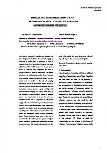
Rotate 1 step ACW & Read Voltage Fig. 4 Hardware implementation of the solar tracker
yes Vnew>Vold?
Vnew>Vold?
no
no
Rotate 1 step ACW
Wait for X2 minutes
no
Rotate 1 step CW
Reset ? yes
End
The circuit consists of an ATmega32 microcontroller that operates at 5 Volt DC. The motor’s stator coils are connected through three voltage controlled mechanical switches. The motor requires 12 Volt and 2 Ampere for operation. 230 Volt 50 Hz AC supply is converted to 12 Volt DC through an adaptor. A 7805 IC steps down the 12 Volt to 5 Volt. A metal heat sink is attached to the voltage regulator to maintain its temperature within limit.
Rotate back to initial position of the panel
Fig. 2 Flow chart of the algorithm.
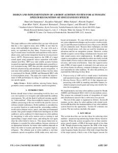
Fig. 3 A serial programmer for AVR microcontrollers
Fig. 5 Hardware implementation of control circuit
Green University Press
3
SADEQUE ET AL: DESIGN AND IMPLEMENTATION OF A SINGLE-AXIS AUTOMATIC SOLAR TRACKING SYSTEM
The total cost of the designed tracker is presented in table II. The cost may vary with the size and rating of solar panel and motor. TABLE II COST OF THE DESIGN
Components
Cost (BDT) 500
Ply Wood Steel Pipe and Sheets
100
Bearings
50
Gears
50
Solar Panel
The total generation of energy is measured by determining the area under the curve in Fig. 6 using composite trapezoidal method of integration. It is found that the 5W solar panel with the tracker generates 32.213 Watt-hour of energy and the panel without solar tracker generates 29.277 Watt-hour. That is, 10.02% incremental energy is possible to be generated if a single axis solar tracker is used to track the optimum position of the panel at any instant of time. TABLE III AZIMUTH ANGLE COMPARISON
350
Potentiometer
Azimuth Angle of Sun (in Degree)
10
ATmega32
Time
220
LM7805
5
5 Volt Relays
90
Design Assembly and Fabrication
1000
Others
350 Total
2725
VI. PERFORMANCE VERIFICATION OF THE DESIGN The fabricated solar tracker was operated for a whole day from 8:00 AM to 5:00 PM and voltage is recorded at hourly interval. At the same time, another solar panel of identical specification is set at a fixed position and voltage is also recorded throughout the day. Short circuit currents at every hour are also recorded for both the solar panels. Two 5W rheostats are used to vary load and measure voltage and current. Fig. 6 shows the hourly power from the 5 Watts solar panel with and without the solar tracker. Power output from 5W Solar Panel 5 With Solar Tracker Without Solar Tracker
4.5
Power (in Watts)
4
3.5
8:00 AM
95.7
97.5
1.8
9:00 AM
104.6
105.0
0.4
10:00 AM
112.8
112.5
0.3
11:00 AM
129.9
127.5
2.4
12:00 AM
181.8
180.0
1.8
1:00 PM
218.2
217.5
0.7
2:00 PM
247.5
247.5
0
3:00 PM
254.5
255.0
0.5
4:00 PM
264.1
262.5
1.6
5:00 PM
271.4
270.0
1.4
Solar energy is an unlimited source of energy. Solar tracker is used to harness this energy to improve the efficiency of the PV system. This paper demonstrates the implementation of solar tracking system in a simple way with the locally available components. Direct use of output data from solar panel makes the system independent of light sensor that requires external biasing circuit. Also the possible errors due to multiple sensors have been eradicated. The use of stepper motor ensures more accurate tracking with minimum error. REFERENCES
2.5
[1]
2
[2] 9
10
11
12
13
14
15
16
17
[3]
Time (8AM to 5PM)
Fig. 6 Hourly solar power output – with and without solar tracker.
The angular positions of the sun detected by the solar tracker and the actual azimuth angles of the sun in the day of experiment at different times are presented in table III. The actual values of azimuth angles are taken from [10]. The position detected by the solar tracker is calculated from the number of rotations required. It is found that the maximum absolute error is only 2.4°.
4
Position Detected Absolute by Solar Tracker Error
VII. CONCLUSIONS
3
1.5 8
Actual Position
Green University Press
[4]
[5]
[6]
M. R. Patel, Wind and Solar Power Systems Design, Analysis and Operations, 2nd ed., Boca Raton, CRC Press, 2006. M. J. Clifford and D. Eastwood, ―Design of a novel passive solar tracker‖, in Solar Energy, 2004, volume 77, p. 269-280. A. H. Yamin, M. N. Ibrahim, M. Idoras and A. R. Zin, ―Embedded Solar Tracking Instrumentation System‖, in Power Engineering and Optimization Conference, 2013, volume 7, p. 223-227. M. I. Hossain, S. A. Khan and M. Shafiullah, ―Power maximization of a photovoltaic system using automatic solar panel tracking along with boost converter and charge controller‖, in ICECE, 2012, volume 7, p. 900-903. A. Yazidi, F. Betin, G. Notton, G. A. Capolino, ―Low cost two axis solar tracker with high precision positioning‖, in IEEE Xplore, vol. 6, p. 216-219, 2006. N. Barsoum, ―Implementation of dual axis solar tracking pilot project‖, Global Journal of Technology & Optimization, vol. 2, p. 49-56, June 2011.
GUB JOURNAL OF SCIENCE AND ENGINEERING, VOLUME 1, ISSUE 1, JULY 2014
[7] [8] [9]
[10]
―ATmega32 datasheet‖, Atmel Corporation, San Jose, CA, USA. ―7805 datasheet‖, Fairchild Semiconductor, San Jose, CA, USA. M. A. Mazidi, S. Naimi and S. Naimi, The AVR Microcontroller and Embedded Systems, 1st ed. , Prentice Hall, 2009. Gaisma. (2013) The Gaisma website. [Online]. Available: http://www.gaisma.com/en/location/dhaka.html.
Fahmid Sadeque was born in on 22 November, 1991 in Rangpur. He passed both his Secondary School Certificate examination and Higher Secondary School Certificate examination form Dhaka Residential Model College with GPA 5.00 in all subjects in the year 2006 and 2008 respectively. He achieved his B.Sc. degree in EEE from Bangladesh University of
Engineering and Technology in 2014. His research interests are Solar Energy, Renewable Energy and Power Electronics.
Dr. Md. Quamrul Ahsan achieved his B.Sc. and M.Sc. degree in EEE from BUET. He achieved his Ph.D. degree from University of Ottawa, Canada. He is currently working as a Professor of Bangladesh University of Engineering and Technology in the department of EEE as well as an Academic Adviser of the Department of Electrical and Electronic Engineering, Green University of Bangladesh, Dhaka.
Green University Press
5