International Journal of Scientific Engineering and Technology Volume No.3, Issue No.8, pp: 1074 – 1077.
(ISSN: 2277 – 1581) 1 August 2014
Design and Implementation of Power Management System Utilizing Supercapacitors for Hybrid Vehicles Marc Angelo Z. Amador, Marc Anthony C. Lina, Alexyz G. Aquino, Filipe A. Gutteres, Alfredo U. Ganggangan, Angelo A. Beltran Jr. ECE Department, Adamson University, Manila, Philippines
[email protected],
[email protected],
[email protected],
[email protected],
[email protected],
[email protected] Abstract—This paper presents the design and implementation of the power management system utilizing supercapacitors for the hybrid vehicle. The researchers develops a system that has monitoring and cell balancing using a microcontroller board which controls, monitors, and charges the battery efficiently to avoid overcharging. The system uses a generator to charge the supercapacitor utilizing it for the electric motor. The supply was in single phase form and it uses step-up transformer with 48V volts switch-mode power supply. Before storing the energy gathered from the generator, the battery will undergo for cell balancing to ensure that all battery pair are equal to each other. The power management system in the project balances the supercapacitors that are connected in series. Keywords—Power Management System, Supercapacitors, Hybrid Vehicle
I. Introduction The technology about automobiles is upgrading very fast. Many electronic devices are now being held up for competition from different automotive companies like Toyota, Honda, and many more. These competitions initiated the revolution of technology for automobiles specifically cars. Today, one of the problems not just in the Philippines but in the whole world is global warming. One of the causes of global warming is the carbon monoxide that is being emitted by our vehicles, and hence because of these effects many companies have therefore come up for a solution that will be environmental friendly and at the same time is affordable. According to C.C. Chan [3], in the next 50 years the populations will increase from 6 billion to 10 billion and the number of vehicles will increase from 700 million to 2.5 billion. If all of these vehicles are propelled by the internal combustion engines, then where shall the oil would be come from? where the emissions should be disseminated? would the sky therefore be permanently grey? The answer to these questions is to strive for sustainable transportation for 21ST century, the growing concerns in the development of electric vehicle technology has taken on an accelerated pace to fulfill these needs. One technology that is escalating is electrical cars. This research paper aims primarily into designing an efficient monitoring and cell balancing system effectively to avoid unnecessary accidents and to regulate the excess current properly especially on oversupply current it will go to the supercapacitors. The study of the battery system for hybrid cars using efficient monitoring and cell balancing system and PIC as the microcontroller can be an innovating paradigm in
IJSET@2014
the car industry especially on hybrid technologies to enhance the efficiency and the effectiveness as well. The project goal is to design and establish a more economical yet sufficient system and add up a battery controlled flow using specific parameters with the help of a microcontroller. Generator is the source of the energy system, it will generate electricity that will go to the charger and give voltage to the battery. This goal can be achieved through extensive study of the prior art and research of the existing hybrid cars that uses the same battery system. The output of the study is a source material that other car engineers can assimilate. The power switch mode DC to AC converter by Ottosson in 2007 [2] is made up of the DC and an AC side, and has a bidirectional power flow. The loss that power electronics dissipates is from the switches associated by the pulse width modulation (PWM) this occurs when the switch changes states from on into off and vice versa, wherein there is short period of exposure to the high voltage, and current also. The dynamic programming (DP) is an important optimization tool that can be used in economics, game theory, artificial intelligence and also in the area of the control systems. Finite horizon optimization will be used in determining an optimal control system for the hybrid electric vehicle over a known driving cycle, using this programming. The Bellman’s principle of optimality which is the basis of the DP which states that, regardless of the initial state and control action, the action controlled has to be then optimal for the remaining problem. Through numerous testing compared to the optimal engine line strategy, the DP cannot then be implemented as real time strategy, since driving in the future has to be known in advance. G. Rosseau, et al. [4] presented control algorithms and laws tested for the reduction of fuel consumptions and pollutant emissions; such as for the dynamic programming (DP) algorithm, the bellman principle, and the equivalent consumption minimization strategy. The architectures of the power train like the mild hybrid and full hybrid are also tested on the different driving cycles to optimize energy distribution between the engine and electric motor. For S. Kermani, et al. [1] in 2008, it uses the so-called real time control approach which formulates empirical rules that is known as the fuzzy logic controller (FLC). It consists of low computational requirement and that usually leads to poor performances. The global optimization algorithm using the classical optimal control theory, which is in this case the fuzzy logic controller was presented. This can be used for
Page 1074
International Journal of Scientific Engineering and Technology Volume No.3, Issue No.8, pp: 1074 – 1077.
(ISSN: 2277 – 1581) 1 August 2014
real time control within a predictive control scheme but therefore consists of low computational requirement. Furthermore, it is not necessary to predict the temporal evolution of the driving conditions. This paper is organized as follows: Section II briefly presents the power management system (PMS) methodology used in this research study & paper. Section III is devoted to the experimental results, which are carried out in order to verify the effectiveness of the proposed method by means of the designed prototype. Conclusion ends the paper at section IV.
II. Methodology The researchers opt to construct a battery system that will promote fuel efficient system in cars using hybrid technology. With this, the researchers use several components to provide the necessary switching process. The study focuses on the two (2) mechanisms that powered the hybrid electric vehicle. One of them is the 48 Volts, 3-phase brushless DC motor. The motor is powered by the super capacitor and it requires a specific motor controller. The controller is the main component of the electric propulsion system. It also has the brake switch and throttle for breaking and speed control. The other mechanism is the 5-hp diesel engine. The diesel engine is the main power source of the vehicle. The solenoid valve controls the flow of the diesel engine of the vehicle. The proponents manipulated these mechanisms to create the fuzzy logic board-based control system for hybrid vehicles.
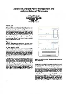
Fig. 3. Block diagram of the module circuit board.
Figures 1 and 3 are the module circuit board (PCB and block diagram). The module circuit board is connected in each of the supercapacitor. Each module circuit board are connected in series and connected also in the master circuit board. The module circuit boards are communicating to the master circuit board in order to gather the data that the master circuit board is displaying in the LCD display.
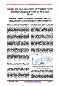
Fig. 4. Block diagram of the master circuit board.
Fig. 1. PCB module circuit board.
Fig. 5. Supercapacitor and charger.
Fig. 2. PCB module of master circuit board and LCD display.
IJSET@2014
Figure 2 is the master circuit board and the LCD display. The master circuit board is connected to the LCD to display the parameters that the battery have. The block diagram is shown in the Figure 4. Also in Figure 5, it illustrates the supercapacitor and the charger. The supercapacitor can also charge fast and it should be monitored by the driver as well
Page 1075
(ISSN: 2277 – 1581) 1 August 2014
International Journal of Scientific Engineering and Technology Volume No.3, Issue No.8, pp: 1074 – 1077. to avoid unnecessary accidents. It has high current and low voltage. The supercapacitors need to connect into series to form 48V. The motor needs 48V in order to operate then the car. The microcontroller serves as the controller of the whole system. It processes the inputs and controls the mechanisms of the vehicle.
Fig. 6. Conceptual framework of the project.
III. Experimental Results In Table 1, each of supercapacitor is tested to know the charging capacity and the charging time of it. The initial voltage is 0.4 Vin, with the 2.6V 2A charge rating values. In the Table 2, five supercapacitors that are connected in series are tested, in 13.5V and 40A charger rating. The researchers conducted 3 trials. The time needed for charging the supercapacitor is similar also to the time for discharging. The supercapacitors will be automatically stopped charging when it reaches 48V which is similar to the output of the charger. When all the cells of supercapacitor fully charged then there will be surge current occurs. This will cause sparking when researchers then shorted the supercapacitors and then reconnect them to the load. The supercapacitors undergo discharged by 4% of its total value after a few minutes and the remaining voltage will be maintained stored in supercapacitor. The motors rpm is directly proportional to the voltage stored in the supercapacitors, the maximum amount of voltage stored will drive the motor faster and increase its rpm and when the voltage in the supercapacitors discharged or lessen, then the motors rpm therefore will decrease. The voltage range of supercapacitors to drive the motor without load is from 29.4V up to 48V, where the 48V is then the maximum voltage stored in the 16 cells of the supercapacitors. The voltage range of supercapacitors to drive the motor with the load is ranging from 34V up to 48V.
Fig. 7. Software flow chart of the project. Table 2: Testing of supercapacitors (series connected). Trial 1:
Table 1: Testing each of five supercapacitors. Trial 2: Time
Trial 1
Trial 2
Trial 3
10 sec
0.4 V
0.4 V
0.4 V
15 sec
0.45V
0.45V
0.46V
20 sec
0.48V
0.49V
0.51V
25 sec
0.53V
0.53V
0.54V
IJSET@2014
Page 1076
(ISSN: 2277 – 1581) 1 August 2014
International Journal of Scientific Engineering and Technology Volume No.3, Issue No.8, pp: 1074 – 1077. Trial 3:
References
IV. Conclusion This paper presents the design and implementation of power management system utilizing supercapacitors for hybrid cars. The components used while constructing an effective power management system are compatible to the whole concept and thus gives the effectiveness of the design. To be able to charge the supercapacitors, a switched mode power supply (SMPS) should be compatible to the rating needed in order to avoid the potential damage of the system. The SMPS specific charger with its input can hence receive the certain amount of voltage from the generator with its output, which can also produce certain amount of voltage that fits to the maximum or total amount of voltage that is needed by the total cells of supercapacitors in order to run the system.
IJSET@2014
i. S. Kermani, S. Delprat, R. Trigui, and T. M. Guerra, “Predictive Energy Management of Hybrid Vehicle,” IEEE Vehicle Power and Propulsion Conference, Harbin, Sept. 2008, pp. 1 – 6. ii. J. Ottoson, “Electric management and control of electric drives in hybrid electrical vehicles,” Licentiate Thesis, Lund University, 2007. [Available]: www.iea.lth.se/publications/Theses/LTH-IEA-1054.pdf iii. C. C. Chan, “The state of the art of electric and hybrid vehicles,” in Proceedings of the IEEE, Feb. 2002, pp. 247 – 275. iv. G. Rousseau, D. Sinoquet, and P. Rouchon, “Hybrid electric vehicles: from optimisation towards real time control strategies,”[Available]: www.dimec.unisa.it/whsv/09_Abstract.pdf v. J. Kendall, “Battery monitoring system for an electric vehicle,” U.S. Patent 5619417 A, April 8, 1997. vi. R. Kotz and J. C Sauter, “Detachable charge control circuit for balancing the voltage of supercapacitors connected in series,” US Patent 20080309295 A1, March 29, 2006. vii. M. J. Sims, et al., “Vehicle battery monitoring system,” European Patent EP2614382 A1, July 7, 2013. viii. M. Kechmire, “Battery monitor with alarm activated by voltage or temperature threshold,” European Patent EP2645117 A1, October 2,2013.
Page 1077