This proposed project is an application of. Faraday's laws of electromagnetic induction to. Transfer power without the usage of physical connectors. According to.
SSRG International Journal of Electrical and Electronics Engineering (SSRG-IJEEE) – volume 3 Issue 4 March 2016
Design and Implementation of Wireless Power Transfer Charging System on Miniature Model Gousia Sultana #1, Deepak.T.R #2, Pratiksha Bhushan #3, Mohammed Azeem#4, Swathi.G.N #5 #1
Assistant Professor, Electrical & Electronics Engineering, K.S.S.E.M, Bengaluru, Karnataka state, India #2, #3 ,#4, #5 Student, Electrical & Electronics Engineering, K.S.S.E.M, Bengaluru, Karnataka State, India
Abstract — In the recent developments of simulation speed and power electronics, the field of wireless power transfer has been developed significantly. In the future transport area, electric vehicles are considered as replacement of oil powered internal combustion engine driven vehicles. Electric Vehicles (EV) have been proposed to achieve environmental friendly transportation. Even though the EV usage is currently increasing, a technology breakthrough would be required to overcome battery related drawbacks. To address battery related limitations, the concept of Wireless Power Transfer (WPT) enabled EVs have been proposed in which EV is being charged while it is in motion or stationary. In this project, the technologies for electric vehicle wireless charging are reviewed using the method of inductive coupling. WPT is the transfer of electrical power from the power source to a load without the use of physical connectors. WPT circuitry is placed inside the vehicle which gets activated when the vehicle reaches the charging area. The primary coil is supplied from the charging station. Flux is radiated out of the primary coil and gets induced with secondary coil present in the EV. The induced voltage from secondary coil is then regulated, rectified and used to charge the EV battery. In this project a miniature model of Electric Vehicle is charged in an effective way without using cables and other plug-in technology. Efficient wireless power transmission is done and control over electromagnetic induction and effective charging of battery will be achieved.
engine driven vehicles, keeping in mind CO2 reduction. Alternate energy Plug-in Electric Vehicles (PEVs) have been proposed to achieve environment friendly transportation. Even though the PEV usage is currently increasing, a breakthrough would be required to overcome battery related drawbacks. Furthermore, PEVs have not been accepted as a preferred choice by many consumers due to charging related issues. This is the major issue faced in the field currently. This proposed project is an application of Faraday’s laws of electromagnetic induction to Transfer power without the usage of physical connectors. According to Faraday’s law, Electromagnetic Flux is induced in a coil when it is linked with the flux produced by another coil. The process of transferring power without the use of any physical connections is called Wireless Power Transfer (WPT). WPT is the transmission of electrical power from the power source to an electrical load without the use of any physical connectors. The proposed WPT system is activated when the vehicle reaches the charging area. Flux is radiated out from the primary coil and gets induced with the secondary coil which is present in the EV. The battery is connected to the secondary coil in the EV and hence battery gets charged.
Keywords — Electric Vehicle (EV), Inductive Coupling, Wireless Power Transmission (WPT), Flux. I. INTRODUCTION The cost of fuels like petrol, diesel etc. has been steadily increasing due to increased number of vehicles and proportional excess usage of fuel. Depleting sources of these fuels are also a major concern. These age old designs of vehicles are the major contributors to the problem of greenhouse gases. The future of automotive technologies is moving toward electric vehicles which are considered as a replacement to oil-powered internal combustion
ISSN: 2348 – 8379
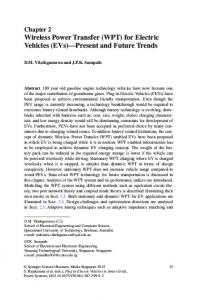
1-Power supply, 2-Primary coil, 3-wireless power Transfer, 4-Secondary coil, 5- system controller, 6-EV battery.
Fig. 1 A basic wireless charging unit for a car.
The above fig.1 represents a basic Wireless Charging (WC) unit for a car. WPT for EV charging has many advantages compared to wired-PEV charging. Inconveniences in wired PEV charging process are major impediments in gaining the interest of consumers. Although the number of researchers is working on WPT technology, there are numerous
www.internationaljournalssrg.org
Page 45
SSRG International Journal of Electrical and Electronics Engineering (SSRG-IJEEE) – volume 3 Issue 4 March 2016
challenges to overcome in making it a commercial level. Acceptable power transfer efficiency at high transfer range, increasing power level, misalignment tolerance and safety considerations are major technical challenges. Our project deals with the charging of miniature model of electric vehicle using WPT. The project aim is to make this technology which is to be branded as the focus of this field, feasible and accessible to all. II. LITERATURE REVIEW Transfer of power wirelessly was discovered and applied by Nikola Tesla. He invented the concept of WPT. This was further improved by other scientists and it was implemented in many applications. Applications like wireless mobile charging, electromagnetic toothbrush, electric vehicles etc., were invented. Electric vehicles were major breakthrough in the fields of Automobile and Transportation [1]. Most approaches to wireless power transfer use an electromagnetic (EM) field of some frequency as the means by which the energy is sent. At the high frequency end of the spectrum are optical techniques that use lasers to send power via a collimated beam of light to a remote detector where the received photons are converted to electrical energy. Efficient transmission over large distances is possible with this approach; however, complicated pointing and tracking mechanisms are needed to maintain proper alignment between moving transmitters and/or receivers. In addition, objects that get between the transmitter and receiver can block the beam, interrupting the power transmission and, depending on the power level, possibly causing harm. At microwave frequencies, a similar approach can be used to efficiently transmit power over large distances using the radiated electromagnetic (EM) field from appropriate antennas [2]. The magnetically resonant coupling was suggested for wireless power transfer (WPT), the theoretical analysis and experimental verifications of several resonant coupling structures have been investigated by several groups. Series-resonant and shunt-resonant structures are two common circuit models which are widely used in WPT. A simple circuit topological structure, the series-shunt mixed-resonant coupling, is presented with better performance in the transfer distance and efficiency. In the experimental verification, a pair of resonant coils with 10-cm diameter was used. The experimental results show that high efficiency of 85% was achieved at a distance of 10 cm (one relative distance) and 45% efficiency at 20 cm (two relative distances) [3]. Various non-contacting methods of plug-in electric vehicle charging are either under development or now deployed as aftermarket options in the light-duty automotive market. Wireless power transfer (WPT) is
ISSN: 2348 – 8379
now the accepted term for wireless charging and is used synonymously for inductive power transfer and magnetic resonance coupling. WPT technology is in its infancy; standardization is lacking, especially on interoperability, centre frequency selection, magnetic fringe field suppression, and the methods employed for power flow regulation. [4]. EV charging is considered as a big load to the utility. The worst case if all EVs are charged at the same time. However, this scenario will be unlikely to happen because of many factors. One of the factors is that the number of charging station is limited. As for the impact of EV battery chargers on the power supply system, it depends on the technology of the chargers. Older version of chargers is based on full-wave rectification using diodes and progressively thyristors are used. Later designs use microprocessor-controlled charging technologies with several algorithms being implemented for parameter monitoring and control. Today, smart battery chargers are available which can interactively communicate with the utility system in order to receive and send information about the state of charge, energy availability, tariffs and management data in general. Such designs have resulted in reduction of harmonic distortion and power factor improvement [5]. III. OBJECTIVES AND METHODOLOGY Aim of the project is to Design and develop the Electric vehicle charging system to charge an Electric Vehicle battery using Wireless Power Transfer Technique. A. Objectives The objectives of project are given below: 1. To design primary and secondary coils using suitable material. 2. To design a wireless power transfer circuitry and obtaining its performance characteristics. 3. To design a power electronic circuit for converting AC to DC and charging Electric Vehicle (EV) battery. 4. To write an embedded program to know the charge level of the battery. 5. To obtain acceptable power transfer efficiency after implementing the circuitry with coils in a miniature model. B. Methodology Adopted: 1) Methodology for objective 1: Literature survey will be made to understand the current National and international status and developments made in wireless power transmission circuit and power electronic convertor systems. The specifications and suitable material used for primary and secondary coils are extracted
www.internationaljournalssrg.org
Page 46
SSRG International Journal of Electrical and Electronics Engineering (SSRG-IJEEE) – volume 3 Issue 4 March 2016
from various journals and specification manuals. Designing the coils for better power transfer. Winding the primary and secondary coils and testing the performance for effective electromagnetic induction.
Conclusions will be drawn based on the validation studies. IV. EXPERIMENTAL WORK
2) Methodology for objective 2: Testing and determining the amount of losses occurred in wireless power transfer. Analysing and simulating the obtained losses for the amount of power to be transferred. Designing the power electronic components and connecting them to reduce power losses in electro-magnetic induction process. 3) Methodology for objective 3: The design will focus on the following specifications: Development of hardware power rectifier and voltage regulator. Designing the power electronic circuit for better rectification. Integrating the circuitry on the Printed Circuit Board. Selection of the battery to be used in electric vehicle. To charge the Rechargeable electric vehicle battery from the rectified output obtained. 4) Methodology for objective 4: The hardware testing to be performed which will include the following steps: Assembly of all the required components on PCB. Winding the primary and secondary coils for effective induction. Supplying the power and testing the charging level of the battery. Decreasing the coils misalignment if present and increasing the power level of charging. 5) Methodology for objective 5:
Fig. 2 Block diagram of WPT circuitry.
In the above Fig.2 the Input of 230V, 50Hz is given to a transformer which steps down the voltage to 12v. The AC power from the transformer is given to primary coil which is implanted in the charging station below road (platform) and also to rectifier to rectify and filter to pure DC by filter circuit. This pure DC is again regulated by the DC regulator. This output of the regulator is fed as supply to the embedded circuitry. The primary coil Flux is radiated out from the primary of the coil and gets induced with secondary of the coil present in the EV (under the chassis). The lithium-ion battery present in the car gets charged. ADC is used to convert analog to digital signals as input to embedded circuitry. An embedded programming is done to know the charging level of the battery. The fig.3 shows a miniature model of Electric Car with lithium-ion battery which acts as a load in this model. The fig.4 and fig.5 represents the Secondary coil mounted on miniature model of Electric car. The primary coil is mounted below the platform (road). In fig.6 the glowing of the LED indicates when the primary and the secondary are in reasonable range for WPT.
The developed system will be connected to car battery and its functioning will be observed and charging time is recorded. The flux interference will be monitored as it has to be under the acceptable level according to Indian standard. The advantages of new design will be validated against the performance of existing system.
ISSN: 2348 – 8379
www.internationaljournalssrg.org
Page 47
SSRG International Journal of Electrical and Electronics Engineering (SSRG-IJEEE) – volume 3 Issue 4 March 2016
A. Primary and Secondary Coil:
Fig. 3 Miniature model of Electric Car with battery
Several factors were kept in consideration while designing the number of turns and size of the primary and secondary coil like, flux density, voltage, losses and other variations. If there is a gradual decrease in the number of turns then consequently the voltage and flux density decreases. As the number of turns increases the flux density increases and in turn the variations and losses also increases. Similarly when there is a gradual decrease in the number of turns the flux density and the voltage also decreases. In Tesla Where, N= number of turns l= length of coil, I= current in Amps And µ = permeability of free space.
Fig. 4 Secondary coil designed for miniature model of Electric Car
Fig. 5 Secondary coil mounted on miniature model of Electric Car
The flux radiated between the coils depends on the Area of the conductor and the flux density as area increase the flux per Webber increases and flux density reduces. The flux radiated is given by: Ø = flux = A * B Where, A=area of the coil. So taking all these parameters into considerations coils are designed. To design primary and secondary coils, the material used is copper. Previously aluminium coils were used which are very cheap but flux radiation is very less. Litz wires are frequently used to lower the parasitic resistance and therefore high Q-factor. Litz coil consists of many individually insulated thin conductor strands wounded in particular patterns. But these wires are prone to skin effect and other proximity effects. So to overcome all these copper wires or hollow copper tube were used even though it’s costlier. Copper is a good flux radiator and efficient. So we used copper material in our project for effective wireless power transfer for this miniature model of electric vehicle.
V. CONCLUSION Literature review on various wireless power transmission system and control of power converter circuit gave a broad idea on WPT systems. Based on the experimental result, the study on wireless power transfer using inductive coupling has much aspect in terms distance of primary and secondary coil, number of turns, area of the coil. Fig. 6 LED to indicate the Wireless power transfer.
ISSN: 2348 – 8379
www.internationaljournalssrg.org
Page 48
SSRG International Journal of Electrical and Electronics Engineering (SSRG-IJEEE) – volume 3 Issue 4 March 2016
Proper alignment and positioning of the coil is achieved in this project. A miniature model demonstration with power getting transferred from primary to secondary is achieved. The same concept could be adopted with scaling features in electric vehicles. REFERENCES [1]
[2]
[3]
[4]
[5]
[6]
[7]
[8]
[9]
[10]
[11]
[13]
[14]
[15]
Nicola Tesla, “The transmission of electrical energy without wires”, Electrical World and Engineer, March 1905. http://www.tfcbooks.com/tesla/1904-03-05.htm, (acc. Dec. 08). William C. Brown, "The history of wireless power transmission," Solar Energy, vol.56, no.1, pp. 3-21, January 1996. Chen, Linhui, Shuo Liu, Yong Chun Zhou, and Tie Jun Cui, "An optimizable circuit structure for high-efficiency wireless power transfer," IEEE Transactions on Industrial Electronics, vol. 60, no. 1, pp.339-349, January 2013. John M. Miller, "Primary-Side Power Flow Control of Wireless Power Transfer for Electric Vehicle Charging",IEEE Journal of Emerging and Selected Topics in Power Electronics, Vol. 3, No. 1, March 2015. Afida Ayob, "Review on Electric Vehicle, Battery Charger, Charging Station and Standards", Research Journal of Applied Sciences, Engineering and Technology 7(2): 364373, 2014 Chengbin Ma, "Wireless Charging Of Electric Vehicles: A Review and Experiments", Proceedings of IDETC/CIE 2011 ASME 2011 International Design Engineering Technical Conferences & Computers and Information in Engineering Conference August 28-31, 2011, Washington, DC, USA. S. J. Gerssen-Gondelach and A. P. C. Faaij, “Performance of batteries For electric vehicles on short and longer term,” J. Power Sour., vol. 212, pp. 111–129, Aug. 2012. V. Etacheri, R. Marom, R. Elazari, G. Salitra, and D. Aurbach, “Challenges In the development of advanced Li-ion batteries: A review,” Energy Environ. Sci., vol. 4, no. 9, pp. 3243–3262, 2011. M. Budhia, J. T. Boys, G. A. Covic, and H. Chang-Yu, “Development of A single-sided flux magnetic coupler for electric vehicle IPT charging Systems,” IEEE Trans. Ind. Electron., vol. 60, no. 1, pp. 318–328, Jan. 2013. G. A. Covic, M. L. G. Kissin, D. Kacprzak, N. Clausen, and H. Hao, “A bipolar primary pad topology for EV stationary charging and highway Power by inductive coupling,” in Proc. IEEE ECCE, Sep. 2011, pp. 1832–1838. A. Zaheer, D. Kacprzak, and G. A. Covic, “A bipolar receiver pad in a Lumped IPT system for electric vehicle charging applications,” in Proc. IEEE ECCE, Sep. 2012, pp. 283–290.
ISSN: 2348 – 8379
[12]
[16]
[17]
[18]
[19]
[20]
[21]
[22]
[23]
[24]
N. Shinohara, “Wireless power transmission progress for electric vehicle In Japan,” in Proc. IEEE RWS, Jan. 2013, pp. 109–111. T. E. Stamati and P. Bauer, “On-road charging of electric vehicles,” in Proc. IEEE ITEC, Jun. 2013, pp. 1–8. N. Puqi, J. M. Miller, O. C. Onar, and C. P. White, “A compact wireless Charging system development,” in Proc. IEEE ECCE, Sep. 2013, pp. 3629–3634. F. Musavi, M. Edington, and W. Eberle, “Wireless power transfer: A Survey of EV battery charging technologies,” in Proc. IEEE ECCE, Sep. 2012, pp. 1804–1810. G. A. Covic and J. T. Boys, “Modern trends in inductive power transfer for transportation applications,” IEEE J. Emerg. Sel. Topics Power Electron. vol. 1, no. 1, pp. 28–41, Jul. 2013. S. Lukic and Z. Pantic, “Cutting the cord: Static and dynamic inductive Wireless charging of electric vehicles,” IEEE Electrific. Mag., vol. 1, No. 1, pp. 57–64, Sep. 2013. M. Kiani and M. Ghovanloo, “A figure-of-merit for designing highperformance Inductive power transmission links,” IEEE Trans. Ind. Electron. vol. 60, no. 11, pp. 5292–5305, Nov. 2013. H. Jin, L. Sungwoo, P. Changbyung, C. Gyu-Hyeoung, and R. Chun-Taek, “High performance inductive power transfer system with Narrow rail width for on-line electric vehicles,” in Proc. IEEE ECCE, Sep. 2010, pp. 647–651. J. Huh, S. W. Lee, W. Y. Lee, G. H. Cho, and C. T. Rim, “Narrow-width Inductive power transfer system for online electrical vehicles,” IEEE Trans. Power Electron. vol. 26, no. 12, pp. 3666–3679, Dec. 2011. J. Y. Jae and K. Y. Dae, “System architecture and mathematical Model of public transportation system utilizing wireless charging Electric vehicles,” in Proc. 15th Int. IEEE Conf. ITSC, Sep. 2012, pp. 1055–1060. J. Y. Jae, K. Y. Dae, and J. Seungmin, “Optimal design of the wireless Charging electric vehicle,” in Proc. IEEE IEVC, Mar. 2012, pp. 1–5. Shailesh R.Kulkarni, S.N.Chaphekar, ―Energy Monitoring Using Wireless Technique‖ SSRG International journal of electrical and Electronics engineering(SSRG-IJEEE), vol. 1,issue 8, oct.2014, ISSN:2348-8379, pp. 12-16 S. In-Soo and K. Jedok, “Electric vehicle on-road dynamic charging System with wireless power transfer technology,” in Proc. IEEE IEMDC, May 2013, pp. 234–240.
www.internationaljournalssrg.org
Page 49