Appears in the 19th International Conference on Parallel Architectures and Compilation Techniques (PACT ’10)
Design and Implementation of the PLUG Architecture for Programmable and Efficient Network Lookups Amit Kumar† Lorenzo De Carli† Sung Jin Kim† Marc de Kruijf† † ‡ Karthikeyan Sankaralingam Cristian Estan Somesh Jha† † University of Wisconsin-Madison {akumar,lorenzo,sung,dekruijf}@cs.wisc.edu {karu,jha}@cs.wisc.edu
Abstract This paper proposes a new architecture called Pipelined LookUp Grid (PLUG) that can perform data structure lookups in network processing. PLUGs are programmable and through simplicity achieve power efficiency. We draw upon the insights that data structure lookups have natural structure that can be statically determined and exploited. The PLUG execution model transforms data-structure lookups into pipelined stages of computation and associates small code-blocks with data. The PLUG architecture is a tiled architecture with each tile consisting predominantly of SRAMs, a lightweight no-buffering router, and an array of lightweight computation cores. Using a principle of fixed delays in the execution model, the architecture is contention-free and completely statically scheduled thus achieving high energy efficiency. The architecture enables rapid deployment of new network protocols and generalizes as a data-structure accelerator. This paper describes the PLUG architecture, the compiler, and evaluates our RTL prototype PLUG chip synthesized on a 55nm technology library. We evaluate six diverse high-end network processing workloads including IPv4, IPv6, and Ethernet forwarding. We show that at a 55nm technology, a 16-tile PLUG occupies 58mm2 , provides 4MB on-chip storage, and sustains a clock frequency of 1 GHz. This translates to 1 billion lookups per second, a latency of 18ns to 219ns, and average power less than 1 watt.
Categories and Subject Descriptors B.4.1 [Data Communication Devices]: Processors; C.1 [Computer Systems Organization]: Processor Architectures
General Terms Design, Performance
1.
INTRODUCTION
Devices that make up the Internet infrastructure are getting increasingly sophisticated due to several reasons. Line rates, data-set sizes, converged network traffic, aggregating voice, video, mobile, Internet traffic, and data-center usage are all growing. In addition new services like scalable Ethernet forwarding [16], protocols to reduce data center costs [3]
Permission to make digital or hard copies of all or part of this work for personal or classroom use is granted without fee provided that copies are not made or distributed for profit or commercial advantage and that copies bear this notice and the full citation on the first page. To copy otherwise, to republish, to post on servers or to redistribute to lists, requires prior specific permission and/or a fee. PACT’10, September 11–15, 2010, Vienna, Austria. Copyright 2010 ACM 978-1-4503-0178-7/10/09 ...$10.00.
‡ NetLogic Microsystems
[email protected]
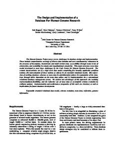
and simplify enterprise management [8] are emerging that require flexibility and programmability. To allow rapid deployment and upgrades, programmability and performance are becoming first order requirements for internet infrastructure. Figure 1 provides a conceptual overview of this infrastructure. The Internet backbone consists of core routers (Figure 1a,b) through which all traffic flows and they run routing protocols. Line cards are their critical components (Figure 1c), which in addition to basic functionality such as buffering packets, perform two processing-intensive tasks: a) lookups into large data structures to determine what to do with a network packet and b) infrequent book-keeping on this data structure. Conventional designs are either overly general purpose or overly specialized. In the general purpose case, programmable network processors perform both tasks, resulting in several trips between processor and on-chip memory. It is highly energy inefficient and the processor organization is ill-suited for this type of processing. Specialization is often favored, where custom hardware modules are built for each data structure (shown by the three blocks in Figure 1c). Examples from the literature include specialized architectures for IP lookup [5, 15, 17, 24], packet classification [14, 32] and signature matching for application identification or intrusion prevention [11, 18, 30]. Ternary CAMs potentially provide richer capability as they can perform associative searches, but face potentially severe power challenges (one 18 Mbit TCAM alone consumes 15 watts) [2]. The general purpose approach is not energy efficient and the customized approach lacks the flexibility, programmability, and deployment “speed” required for emerging services. This paper presents the design of a flexible yet energy efficient general lookup module called PLUG: pipelined lookup grid. PLUGs are meant to replace both SRAMs and TCAMs and augment network processors as shown in Figure 1d. Conceptually, in the PLUG model, the inherent structure in the lookup data-structure is exploited by physically mapping the data structure to on-chip tiled storage as shown in Figure 2. Large “logical pages” are constructed representing parts of a data-structure that belong to one logical level (like nodes at one level of a tree). Small blocks of code – code-blocks – are associated with each such logicalpage. They operate without any global information, perform reads or writes to their logical-page, and determine the next logical-page to be looked up by producing a network message. Code-block execution is triggered by arrival of such a network message and is terminated upon sending a message for the receiver. Logical pages are partitioned into explicit
Line card
Processor
Control
b) High-end router
DRAM
Processor
v
v
v
v
TCAM
PLUG
SRAM
ASIC
Interface
a) Internet infrastructure
Interface
Mobile ATM
Line card
Voice
Router
Line card
Router
v
v
v
v
DRAM
c) Line card
d) PLUG-based line card
uCores
Internet Provider Internet
SRAM Routers e) PLUG Tile
Figure 1: Conceptual overview physical-pages that match the storage space available on a given tile. Data-structure lookups are thus transformed into a structured pipeline of computation and memory access. De Carli et al. [9] introduce this model and showed how core network processing algorithms are amenable to this model. This paper describes the architecture and full system making the following contributions1 : 1. A description of the PLUG architecture and its bufferless, contention-free on-chip network (Section 2). 2. The construction of the PLUG compiler(Section 3). 3. Description of synthesized RTL and of implementation lessons learned from the design experience (Section 4). 4. Evaluation showing that PLUGs can sustain a billion lookups per second at under 1 watt for diverse workloads, and they closely match or exceed the performance and power efficiency of specialized solutions (Section 5).
2.
ARCHITECTURE
After a brief background on the programming model, this section presents a design space study of lookup modules. We then describe the PLUG architecture including its ISA and detailed microarchitecture. PLUG Overview: The basic concept of the PLUG programming model is to transform all lookup operations into pipeline of small stateless computations on regions of memory[9]. It assumes an abstracted view of the hardware as a set of memory+compute units (tiles) logically connected through an all-to-all broadcast network, thus simplifying programming. As shown in Figure 2b the program is expressed as a dataflow graph of logical pages with code-blocks associated with each page. A full application is shown in Figure 5.
2.1
Design space
Figure 3 presents a design space of architectures to build lookup modules deconstructing them in terms of computing, memory, and interconnection. The graph above shows flexibility, performance, and hardware efficiency of these designs. They all interface to the rest of the system in the same way, by accepting a lookup request and generating a reply. We assume system software can map our programming model or some other representation of the data structure to the memory resources. Throughput is the primary constraint 1 (1) supplements and expands material in [9]. (2), (3), and (4) are entirely new contributions
and we assume a model where a new lookup request arrives every cycle. At the left extreme, is the fully centralized design which provides most flexibility but is highly inefficient. Computation nodes can be mapped to any available core and data can be laid out across the memory. The crossbar allows all cores to get to all memory, but is impractical to build for more than a handful of cores. The latency of crossbar will become too high resulting in very poor performance. On the right extreme is the completely distributed design that creates a tile with one router, one memory, and one core. The design is highly inflexible because the memory nodes are now limited to the size of one memory. Second, it has very poor performance, because throughput is limited to the rate of 1 every X cycles, where X is the slowest codeblock’s latency. Figure 3c shows an intermediate design point that increases throughput by providing N cores in every tile and increasing the size of the memories. This provides a new core for lookup operations arriving in successive cycles and can thus provide high throughput. However, this forces even small memory nodes into utilizing an entire tile resulting in reduced scheduling flexibility. Figure 3b shows the “best” design point which aggregates together an arbitrary number of memories, cores, and routers. These are then exposed to the ISA as many virtual tiles and the compiler can assign a subset of resources to each dataflow graph node. This allows almost as much flexibility of the fully centralized design and achieves the simplicity and efficiency of the fully distributed design. Conventional network processors (for e.g. chips like EZchip, Netronome/IXP and Freescale) resemble Figure 3a and further render themselves inefficient for lookups because the processors are overdesigned for this task and constantly burn energy waiting for replies from SRAM. They typically include specialized modules or instructions for handling tasks such as packet parsing and queuing/scheduling that are not addressed by PLUG. With respect to lookup processing, NPUs typically use a small lookup processing unit (LPU) on-chip connecting to off-chip DRAM / SRAM / TCAM holding the forwarding tables the lookups are performed in. SRAM or DRAM based solutions require multiple memory accesses for each packet. At line speeds of 40Gbps and higher, the cost of providing the required off-chip memory bandwidth becomes problematic. We see PLUG as a replacement for TCAMs or the DRAM/SRAM-based lookup unit. In PLUGs, a single request internally triggers multiple memory accesses and processing as needed for completing the lookups required by one packet. In our quantitative comparisons in Section 5 we compare performance to specialized lookup modules.
p.proto
Offloaded to PLUG
p= get_pkt_from_interface(); x = tree0.lookup(p.proto); y = tree1.lookup(p.hdr); if (x < y) { ...... } z = htable0.lookup(p.key); .... send_pkt_to_interface();
64K Pg 0
Code-blocks
128K Pg 1
Pg 0.0
Pg 1.0
170K Pg 2
Pg 2.0
p.proto
Pg 1.1
Pg 2.1
Pg 2.2
0.0
1.0
2.2
1.1
2.0
2.1
x
x
a) Application pseudo-code
b) Lookup data-structure
c) PLUG program/lookup object with codeblock and logical pages
d) PLUG scheduled object: physical pages with code-blocks
e) Pages mapped to tiles
Figure 2: PLUG software overview. The bold outline indicates pages/tiles accessed for an example lookup.
Figure 3: Architecture Design Space Chips like Tilera resemble Figure 3d and are inefficient because of the lack of scheduling flexibility of the data structure, their computation capability is again over-designed for lookup, and provide an interconnection network that is overdesigned for this task and hence inefficient. Since PLUGs are specialized for lookups, their processing elements are far simpler and the architecture can devote most of the resources to storage. By using the guarantees provided by the programming model, we simplify the routers and avoid the need for any buffer or flow-control while still providing the abstraction of a fully connected network with static deterministic delays. PLUGs and Tilera/RAW differ radically in computation/storage ratio. PLUGs are are typically targeted for lower-layer network processing (layer 2-4) operating in the sub 2-watt regime. Tilera/RAW is designed for higher-level (layer 4-7) network processing operating in the 10-20 watt regime. Comparing IP Lookup on RAW [22], PLUGs can provide 512 Gb/sec lookup-throughput on 64-byte packets, RAW provides 15 Gb/sec throughput performing full routerprocessing. Normalizing for the technology improvements, PLUGs at 90nm provide 300 Gb/sec throughput.
2.2
PLUG Architecture
Figure 4a shows the high level overview of the PLUG architecture showing 4 tiles with six networks (denoted by different colors). Our overriding principle is to use simplicity to achieve design and energy efficiency and devote maximum area to the SRAMs. It is a tiled multi-core multi-threaded architecture with a very simple on-chip network connecting neighboring tiles only. One of the input ports on the topleft tile and output ports on the bottom-right tiles serve as
canonical external interfaces. Execution of the programs is data-flow driven by messages sent from tile to tile. Furthermore the computation in each core is stateless and the message carries any state required. The interconnection network creates a logical abstraction of all tiles connected to all other tiles and by enforcing restrictions on when messages can be sent, it creates a conflictfree network. The reason for providing six networks is to allow multiple out edges in the dataflow graph. With restrictions on the ordering of memory instructions (Rule 2 in Section 3), the memories effectively provide an abstraction of a fine-grained global lock for any loads and stores thus providing serialization of all lookups. PLUG ISA: The PLUG ISA closely resembles a conventional RISC ISA, but with two key specializations. It includes additional formats to specify bit manipulation operations and simple on-chip network communication capability. Table 1 outlines the different ISA formats for our 24-bit instructions with a 16-bit datapath (which was sufficient for our workloads). The register space is quite small: one 16-bit program counter per thread, and thirty-two 16-bit registers per thread. The ISA provides variable length loads to match data-block sizes and amortize the cost of one SRAM access. Sizes 2, 3, 4, 6, 8, 10, 12, 14, and 16 bytes are supported and are written to consecutive registers.
2.3
Microarchitecture: Tile
A tile consists of a core cluster, memory cluster, and router cluster as shown in Figure 4b-d. The figure shows 32 cores, 4 memories, and 6 routers - referred to as the 32Cx4Mx6R configuration. Multiple cores allow a new packet
R1
R2
R3
R4
R5
uCore
R6
I-Mem
PC
from router
Valid bits
64
Register File
from SRAM Core 1
Core 32
c) uCore
64
to router to SRAM Input ports
North South East West
16
16
Local 128
Addr
16 Gen
M1
M2
M3
M4 Arb
Virtual Tile 0
Virtual Tile 1
a) PLUG 4 Tile Organization
b) Tile
Virtual Tile 2
Output ports
...
Arb
North South East West
Local
d) Router
e) Memory
Figure 4: PLUG Chip and Tile Organization: 32Cx4Mx6R Format name R-format M-format I-format C-format N-format
Purpose Manipulate registers Access memory On-chip n/w communication, bit manipulation Control flow Create n/w msgs
Instruction Fields 6-bit 5-bit 5-bit 5-bit 3-bits Opcode Rsrc0 Rsrc1 Rdst Opcode Rsrc0 Rdst Imm0 Opcode Rsrc0 Rsrc1 Imm0 Imm1 Imm2
Pipeline
Opcode Rsrc0 Imm0 Opcode Rsrc0 Imm0 Imm1 Imm2 Imm3
F D E/Branch F D S Wremote
FDEW F D E M1 M2 M3 W FDEW
Table 1: PLUG ISA. The immediate field describes network number or values to extract bit fields. Last column shows pipeline stages for each type. S is a network send stage. to be processed every cycle (which we refer to as a thread context) by providing a new core. These resources are exposed as virtual tiles which can be configured to consist of a subset of these resources. Thus, a single virtual tile cannot have more than one logical page. Figure 4b shows a PLUG tile configured as three virtual tiles, with two, one, and one memory per virtual tile respectively. The abstraction of virtual tiles provides three key benefits: a) logical pages with different types of memory, computation, and router requirements can be mapped on a single physical tile, b) efficient sharing of resources, and c) control of scheduling losses enforced by the propagation discipline (Section 3.2). Providing arbitrary connection between N cores, M memories, and R routers can result in high wiring overhead and hardware complexity. However, we exploit the simplifications provided by the programming model. In a cycle: • A message on a network needs to be delivered to only one core. Hence one input bus per network with all cores reading from it is sufficient without any arbitration. • No more than one core will access memory. Hence one memory bus per memory is sufficient. • No more than one core will send a message on a network. Hence one output bus connecting the core cluster to the router cluster per network is sufficient. These simplifications result in a simple set of four buses driven by tri-state drivers between router cluster, core cluster, and memory cluster.
2.4
Microarchitecture: On-chip Network
Each tile also includes a simple router that implements a lightweight on-chip network (OCN). Compared to conven-
tional OCNs [13], this network requires no buffering or flow control as the OCN traffic is guaranteed to be conflict-free. The router’s high level schematic is shown in Figure 4d. The routers implement simple ordered routing and the arbiters apply a fixed priority scheme. They examine which of the input ports have valid data, and need to be routed to that output port. On arrival of messages at the local input port, the data gets written directly into the register file. Because of code-generation rules (Section 3) contentionfree routing with static delays is possible. The routers also efficiently support dataflow edges that semantically multicast to multiple nodes. Encoding and routing to multiple arbitrary targets is inefficient. Instead we support a restricted multicast, which delivers messages to all intermediate nodes along the way to the final destination. Since the routing algorithm is exposed to the compiler, it can schedule multiple targets of a node such that they all fall on intermediate tiles en-route. To implement discard edges, when there are multiple requestors, a fixed priority scheme (N orth > W est > South > East in our implementation) determines which of the ports gets selected and data from other ports are dropped. Our design provides six networks N1 through N6 with the network message consisting of 80 bits (16-bits header and 64-bits data). Registers R0 through R5 are reserved for headers. Registers R8 through R31 get data. The header information contains five fields: destination encoded as a 4-bit tile number, a 2-bit field to encode the virtual tile number, a 4-bit type field to encode 16 possible code-block ids, and a multicast bit.
2.5
Microarchitecture: µCores
The µcores shown in Figure 4c each executes one thread and they all share the SRAM and routers. Each µcore is a simple 16-bit single-issue, in-order processor with only integer computation support, simple control-flow support (no branch prediction), and simple instruction memory (256 entries per µcore). The register file is small and partitioned to provide four consecutive entries on the read/write ports to feed the router. They can output requests to memory or to the router every cycle, and static instruction scheduling guarantees that exactly one thread and hence one µcore will make such a request. The result of the SRAM access is broadcast to all the µcores and predictable SRAM access delays ensure that only the correct µcore uses up the data. The same OCN is used to deliver instructions to the instruction memory, which is typically done once at startup (or infrequently).
2.6
Memory cluster
The design of the cores and routers was straight-forward. The design of each memory proved to be a challenging problem. Since the main goal of the PLUG architecture is flexibility, we wanted to support different word sizes to access the memory. While implementing different applications, we found this to be important. We elucidate a few below. IPv4 has six different word sizes when implemented with the Lulea algorithm, namely 12, 8, 14, 2, 6, 9 bytes. SEATTLE (protocol for large enterprises) has 4 word sizes: 9 byte hostlocations, 16-byte hashes in a DHT-ring, and 8 byte destinations. Since PLUGs are lookup engines memory utilization is key and hence this support. So the ISA views and addresses the memory in terms of the logical word size which is configured for each PLUG tile. The hardware is responsible for translating this to a physical line address. Our application analysis revealed that 16 bytes is the largest word required. Supporting all word sizes from 1 to 16 would mean a divider prior to SRAM access to compute the line address - which adds both delay and area. Instead we decided to provide a set of most common word sizes and the application writer rounds up to the larger word size. The tradeoff is that once a physical line size of N bytes is picked, then depending on the word sizes that are supported a divider that can divide by some numbers may be needed, and some bytes will be wasted on each line. For example with a physical line size of 16 bytes and a logical word size of 11 bytes, 5 bytes in every line are wasted (31.25% line wastages). But no divider is needed because logical line address is the same as the physical line address. Supporting a word size of 3 bytes will mean a divider by 5 (five 3-byte words on a line) and 6.25% line wastage. On the other hand, with a logical line size of 256 bytes and supporting all word sizes 1 to 16, in the worst case 9 bytes are wasted for a logical word size of 13, which is a wastage of only 3.5%. However, for this design a divider that can divide by 3, 5, 11, 7, and 14 is required. Second, with a 256 byte line, the SRAM has only 256 lines, and would require further sub-banking and many bit-line segments internally. The additional physical area required for such a divider is about 20% the size of a 64KB SRAM 2 . Based on a design search, we arrived at 48 bytes to be the optimal physical line size and supporting the following word sizes 3, 6, 7, 10, 11, 12, 14 in addition 2
We implemented and synthesized these specialized dividers.
to powers of 2. For intermediate word sizes the application writer rounds up. For this design, we only need a divide-by3 unit (equivalent in size to an 8KB SRAM). Furthermore, the worst case wastage is 16% for a word size of 10 bytes. For a 64KB memory we use three 21KB SRAM arrays with 16 byte line size.
2.7
Beyond network processing
While the PLUG system is designed for network processing, the principles and the architecture are potentially applicable in other domains as well. Digital signal processing and many types of stream computing have a similar partition of control-plane and data-plane that network processing has and can map well to PLUGs. Architectures like the Cell processor which use software programmed memories, can use the PLUG programming model and scheduler for implementing irregular data structures. More generally, PLUGs can be used for explicit distribution of computation on an explicitly partitioned memory hierarchy like on-chip SRAM banks that make up lowerlevel caches. Recursive data-structures can be mapped and “looked-up” by the processor, instead of traditional pointerchasing with the processor. This approach is elegant and can significantly reduce energy spent in processor-cache roundtrips. Applications such as ray tracing, graph traversal in several EDA problems, Markov-chain traversal for AI algorithms spend significant processing time on such data structure queries. Specifically, consider a kd-tree which is used in ray-tracing to determine light-ray/object intersections and contains many levels (up to 20) and is several megabytes in size with poor level-1 cache locality. Using the PLUG model the kd-tree can be spatially laid out in memory, and the processor initiates a single lookup, which triggers traversals within the memory with associated code-block executions, resulting in a final message back to the processor with the intersecting leaf node. While the PLUG is traversing, the processor simply idles or continues processing a different thread. With 3D stacking and large L3-caches becoming practical, PLUGs can be integrated as another type of cache.
3.
COMPILER
This section first presents background: a description of the primitives of a PLUG program and an example. We then present the design, implementation and principles for generating contention-free code in the compiler.
3.1
Interface and PLUG Programs
To the rest of the chip, the PLUG is one or more pipelines, each storing a lookup object: a data structure that can be accessed only through small number of routines. As shown in Figure 2a, routines are offloaded to the PLUG. Invoking a routine results in submitting a message (whose content is the parameters passed from the routine) at the input interface of the pipeline and if the routine produces results they appear after a fixed number of cycles in a message at the output interface of the pipeline as shown in Figure 2e. In our development environment, a PLUG object is a C++ object, and logical pages are typically lists of datablocks. Code-blocks are methods in the object, and messages are arguments to a codeblock and return values. In addition to memory access, typically codeblocks perform bit manipulations for parsing data structures, compare values, and
compute offsets, addresses, and tile targets. The dataflow graph is explicitly specified by marking source and destination logical pages. An Example: Figure 5b shows the dataflow graph, codeblock source code (5c), and assembly code(5d) for an application – IPv4 lookup. The data structure is an adaptation from literature [10]. It is a compressed three-level multibit trie with strides of 16, 8 and 8. Each level of the trie is implemented by two logical pages and uses bitmap compression (a variant of run-length encoding) and list compression (explicitly specifying non-zero indices). Data blocks are bitmaps (16-byte), lists (16 bytes), and entries (2 bytes).
3.2
PLUG Compiler
The PLUG compiler takes as input the C++ implementation and must perform the following functions: a) generate assembly code for code-blocks, b) partition the logical pages into smaller physical pages c) schedule them to specific tiles, and d) assign dataflow graph edges to networks on chip. Simple features of the architecture are exposed to the compiler to support the typical communication patterns shown in Figure 5a. Multiple networks support the delivery of multiple messages from one source to one destination (divide and combine pattern). Multicast messages implement the spread pattern to send one message to multiple targets. Finally, static arbitration priority in the network decides which message gets discarded on a conflict for the discard pattern. Code-block compilation: PLUG source code is a subset of C++ with a few PLUG assembly language intrinsics. Built using the LLVM compiler infrastructure [19] our backend converts LLVM bytecode into PLUG assembly code. The code generation presents some interesting challenges because of PLUGs support for variable word sizes (section 2), and bit manipulation instructions (for example copying n bits from bit-position i to bit-position j). Details are omitted in the interest of space. Partitioning pages: The first step is to create physical pages that are each small enough to fit within a single memory. For most applications, the logical page is a list of datablocks, in which case the scheduler simply creates equal sized chunks. For a few applications like IP Lookup, there is a word-level dataflow graph, connecting words between logical pages. To minimize, the number of out-edges from a physical page, the scheduler implements a graph clustering algorithm at the word-level. Scheduling: Second, this physical dataflow graph is scheduled to the PLUG chip. We use a greedy algorithm which ranks all the tiles based on distance from the top-right hand corner, considers the nodes of the dataflow graph in breadthfirst order (with some tweaks for multicast edges) and assigns them to tiles. The algorithm ensures the following: a) enough cores are available in a tile (hence code generation is done first), b) the tile is reachable from all its source tiles, c) enough networks are available to deliver the input messages. Since the PLUG provides a mesh interconnect, every page is guaranteed to be reachable from every other page. However, to guarantee no network conflicts occur, additional scheduling rules must be enforced. We discuss these in the next section. Network assignment: Each edge in the dataflow graph is assigned to networks on chip, specified in the ISA using an immediate operand of the snd instructions. Naively, the number of networks required is equal to the maximum
number of outgoing edges from any node. However, this network assignment is effectively a graph coloring problem and we currently use a greedy heuristic. For applications like ETHANE which has nine 64-bit inputs, as shown in Figure 7f, five networks are sufficient using graph-coloring.
3.3
Contention-Free Code
For simple integration to the network processor, lookup modules must produce results with fixed delays. Traditional tiled architectures cannot guarantee such regularity as messages can get delayed due to network conflicts and memory contention. One of our key innovations is the PLUG code generation rules that ensure fixed delays required by the simple architecture. The four rules are: Rule 1) Code blocks perform at most one memory access. Rule 2) All of them perform the memory access the same number of cycles after the start of the code block. Rule 3) All code-blocks that send messages, do so the same number of cycles after they are started. Rule 4) For a physical page with multiple sources, the global scheduler ensures that all incoming paths at a given internal tile have the same latency from their respective sources. The first three rules guarantee conflict-free execution within a tile, and the fourth guarantees a conflict-free network. Propagation disciplines: If the hardware performs adaptive routing, it is impossible for a software scheduler to enforce Rule 4. The PLUG network implements deterministic dimension-order routing and on such a network, the rule translates to forcing all traffic into one of four patterns (referred to as propagation disciplines): a) right and down, b) left and down, c) right and up, and d) left and up. If primary external inputs arrive at the top left hand corner, the right and down is the only propagation allowed. Implying that, for two logical pages a → b, all physical pages for page b, must be mapped to the right and below all physical pages of a. While this results in scheduling losses, the principle provides several benefits: Conflict-free execution: we can avoid all conflicts for resources thus simplifying the lightweight cores and on-chip routers. Specifically, we utilize a stall-free core pipeline and an on-chip network without buffering and flow-control. Atomicity for complex modifications that require multiple updates routines, because the fixed delays ensures that at every tile, the memory operations occur in exactly the same order in which the respective routines entered the pipeline. Global synchronization can be achieved by scheduling. Results of different computations performed in parallel can be combined by having them arrive at a tile in the same cycle. While the programming rules appear hard at first glance, recall they are enforced by the compiler. The PLUG programmer works at the level of logical-pages (linked together in a data-flow graph). PLUG programs are written in C++ using the PLUG API. The PLUG compiler generates assembly code enforcing the programming-rules and maps the pages to as many tiles as needed. In our experience, PLUG programs were easy to write.
4.
PROTOTYPE IMPLEMENTATION
We have implemented in Verilog, verified, and synthesized a PLUG chip in foundry-provided 55nm technology library. This section first describes our early estimation methodol-
X
Divide/combine
Spread
Discard
a) Common Communication patterns
input
IP 0-15 bitmaps, chunk indices
IP 0-15 pointers, results
IP 16-23 bitmaps, chunk indices, lists
IP 16-23 pointers, results
IP 24-31 bitmaps, chunk indices, lists
IP 24-31 results
output
b) Data flow graph for “Lulea” algorithm – multibit trie with strides 16-8-8 with compression of trie nodes ld112 R12-R18 [R11]; read memory mvp 5, R19,0,R2,12 ; last 5 bits sub R20,R19,16 ; of ip-address cut R15,R19,0 ; count bitmap cut R11,R19,12 add R15, R15, R11 je R20, loop2 ; count 2nd bitmap? cut R18,R19,0 cut R14,R19,12 add R15, R15, R14 j loop3 loop2: Nops ; pad with nops loop3: add R1,R15,R13 ; add base index add R4,R14,R12 ; snd R0-R4 N1 ; send message
void l_work(plug_logical_message *msg) { int ip_part = msg->get_data(0); int addr = msg->get_data(3); p_word block = get_l_data_word(addr); r_ret = block[0]; // base index // count bitmap for(int i = 0;iget_data(1) ); omsg.data.set_word(2, msg->get_data(2) ); omsg.data.set_word(3, c_ret ); send(o_msg); }
mvp macro is expanded into more instructions
c) Codeblock source code
d) Codeblock assembly code
Figure 5: Communication patterns and IP lookup example. ogy, our implementation, contrasts results with our early estimates and concludes with lessons learned.
4.1
Early Estimates: are PLUGs buildable?
To understand the feasibility of the architecture, we constructed a simple delay, area, and power model using existing processor datasheets and CACTI [29]. Our target frequency is 1 GHz to sustain one billion lookups per second, area target is 1 mm2 per tile to limit local wire delays, and technology node is 55nm. To match application needs, we require 32 cores, four 64KB banks, and 6 networks in a tile. For modeling the µcore cluster, we used the Tensilica Xtensa LX2 [28] as a baseline for one µcore. This processor is a simple 32-bit, 5-stage in-order processor and occupies 0.206mm2 built at 90nm. Simplifying to a 16-bit data path and scaling for technology, our model projects area of a µcore to be 0.028mm2 . We conservatively assumed the interconnect’s area is 10% of processor area, similar to reported results [13]. Based on this model, a single PLUG tile’s area is 2.34 mm2 . Power modeling: Using CACTI we estimate worst case power by assuming the SRAM is accessed every cycle and uses low standby power transistors (LSTP) cells. We used Xtensa LX2 processor data-sheet to derive the power consumption of our 32 µcore cluster. We model interconnect power per tile as 15% of processor [31]. The worst case power estimate for a tile is 489 milliwatts. We then built a simple analytical model for chip power for full applications. Dynamic chip power can be derived by considering the (maximum) number of tiles that will be activated during the execution of a routine (activity number A). Thus, worst case power can be modeled as A tiles executing instructions in all µcores and one memory access every cycle.
The final chip power = [ (leakage power per tile) * (total number of tiles) ] + [ (dynamic power per tile) * (activity number) ]. Given an application with L logical pages, and code blocksPof length ci associated with each, the activity L−1 number is i=0 ci /C, where C is the number of cores in a tile. These early models suggested a PLUG chip would be practical and drove early design decisions.
4.2
Prototype implementation
Design: We designed the tiles hierarchically, with cores, routers, and memories combined to create a core cluster, memory cluster and router cluster. The chip is simply instantiation of multiple tiles. The design was implemented using Verilog, simulated with Synopsys VCS and verified against our reference PLUG simulator (details in Section 5.1). We synthesized the design using the Synopsys Design Compiler with a foundry-provided 55nm technology library. Synthesis results: One PLUG tile with 32 cores, four memories 64KB each and 6 routers is 3.57mm2 . This was the best configuration derived from application analysis. Table 2 summarizes our synthesis results. The second column shows our ASIC-synthesis results, and the third column shows model estimates. Delay and timing optimizations can improve these results, since we did not perform any physicaldesign optimizations. Overall we exceeded our 1 GHz goal and are well within the 5 watt target.
4.3
Lessons learned
The co-designed approach of the PLUG system involved algorithmic design, formalizing the programming model, and software-stack implementation. With respect to the hardware, we built early models that estimated the area, fre-
Core cluster Router cluster Memory cluster Tile Frequency Power
Area (mm2 ) 55nm ASIC Early estimates 1.13 0.89 0.38 0.21 2.06 1.24 3.57 2.34 1.1 GHz 1 GHz 56 milliwatts 489 milliwatts
Table 2: PLUG Implementation 10.0
1-VT 1-VT-L 4-VT
Power (watts)
9.0 8.0 7.0 6.0 5.0 4.0 0.0
10.0
20.0 30.0 Memory (MB)
40.0
50.0
Figure 6: PLUG early design space exploration. Die sizes of 21, 64, 128, and 200 mm2 . quency, and power of the cores using existing processor datasheets and we used CACTI for memory estimates. This initial high-level design drove our design choice in algorithms, what sizes pages should be, how complex code could be, what target throughput to sustain, and architectural exploration. We now have a full hardware design and complete software stack which provide accurate projections. Early Modeling/Estimates: Our initial area, frequency, and power estimates for the core cluster ended up being highly conservative. Even though we picked a relatively aggressive processor, even our unoptimized design was 10% faster in frequency. We were surprised by the comparison to our early estimates. Our area estimates were overly optimistic by 34% with the most divergence in the memory cluster estimates. Our early estimates assumed a single 64 KB SRAM bank. Our implementation uses three 22 KB sub-banks and divider in each bank. Our power estimates were surprisingly off by an order of magnitude in spite of projections we made to account for LSTP devices. Design time and Optimizations: The largest portion of the hardware design-time was devoted to developing the architecture, refining the idea of virtual tiles until it could be implemented. The design of the memory cluster was the hardest since we simply did not know what the most frequent type of word sizes are early in the design. After designing and evaluating several approaches, we decided on the multibanked approach. Since the cores are quite simple and the memories dominate the design, the Verilog entry and synthesis was done in 6 person months. We did almost no timing and area optimization since our initial design exceeded the 1 GHz clock frequency. Design space exploration: We discuss a design space exploration of different PLUG configurations which shows sensitivity to different parameters and guided our early design considerations. We examine different die sizes (21mm2 , 64mm2 , 128mm2 , and 200 mm2 ), different PLUG configurations, and use a single tile’s area to determine how many tiles fit on a die. For power estimates we consider our most
power-hungry application IPv6 (Activity number = 14.9). The 21mm2 die sizes gives us 16 tiles in the 4-VT configuration and sufficient memory (6.3MB) for all applications except IPv6 (for which we scaled down the data-set). The configurations we consider are described below and all have 32 cores and 6 routers: • 1-VT: One virtual tile per physical tile. (32Cx1Mx6R) • 1-VT-L: Same as above with a larger memory: 256KB. • 4-VT: Four virtual tiles per physical tile, 64KB memory banks. (32Cx4Mx6R) For our current design, the results show that the 1-VT configuration is the most energy efficient and all configurations are under 1 watt. With our initial models due to incorrect power estimation, we thought the 1-VT configuration was not efficient because it devotes lots of area to the cores. Figure 6 shows a scatter plot of memory versus power based on our early “incorrect” model. For small memory sizes (4 to 8MB), all configurations are under 3 watts. As the amount of memory increases, the 1-VT configurations become inefficient because they devote more area to the cores which are less power efficient than the memories. The 1-VT-L is the most power efficient and the 4-VT is almost as good. However, the 1-VT-L configuration requires larger area due to scheduling losses as shown in the next Section. The power efficiency problem of the 1-VT configuration suggested by our models turned out to not be true. This power efficiency problem was a secondary motivation for virtual tiles. Compiler and software stack: The software stack proved harder and took longer to implement than the hardware. We developed two versions of our development framework, before arriving at the final abstraction of C++ objects with logical pages represented as a first class object. With our current framework, a single code base can be developed and debugged running on an x86/gcc backed with the PLUG runtime. The same codebase is passed to our PLUG compiler which generates PLUG assembly code. The run-time development and compiler development together was 18 person months. Implementing the applications took another 18 person months with several developers involved. Scheduling flexibility: After we built our software stack, scheduling algorithms, and code generation we were able to simulate full applications and analyze different schedules. The detailed tools we developed showed that we could significantly relax our scheduling constraints. Since the PLUG network is statically scheduled, we proposed the use of propogation disciplines to force all child nodes to the right and below parent nodes. Using a compiler peep-hole optimization (hand-optimized now), we can relax this constraint and place nodes anywhere as long as we can slow down codeblocks at different tiles by different amounts so there is still no conflict.
5.
EVALUATION
Evaluation is a challenge because few comparable designs exist that provide the flexibility of the PLUG. So we present sensitivity studies between the different configurations and a comparison to best-of-breed implementations for each network task. We examine throughput, area, power, and latency. Our results show PLUGs sustain 1 billion decisions per second, at 58 mm2 , consuming typically less than 1 watt, with latencies from 18ns to 219ns across a diverse workload set. We demonstrate that PLUGs are competitive with bestof-breed implementations and can exceed their performance.
0
14
1 2
0
1
2
3
20
4
Output 5
3
6
7
4
1 1
1 1
2 2
2 2
0 2
1
1 1
1 1
2 2
2 2
3 3
3 3
3 3
3 3
4 4
4 4
3 3
3 3
4 4
4 4
1
2
3
4
7 8
9
10
11
15 16 17 18 21 22 23 24 35
5
6
12
13
30
3 3
4
4 4
4
3 3
4 4
4 4
5
4 4
2
6
2
3
31 32 33 34
7
1
1
25 26 27 28 29
4
3 3
0
4
0
Output
5
6
8
6
7 8
Output
7
4 5
1 2
3
10
9
0 1
0 1
2 2
2 2
2 2
2 2
2 2
2 2
0 0
0 1
1 1
2 2
2 3
3 3
1 1
1 1
3 3
3 3
4 4
4 4
7 7
7 7
2 2
2 2
2 2
2 2
2 2
2 2
2 2
2 2
4 4
4 5
5 5
6 6
6 7
7 7
2 2
2 2
5 5
5 5
6 6
6 6
8 8
8 8
2 2
2 2
2 2
2 2
2 2
2 2
2 2
2
8
9 9
9 9
9 10 10 10 10 10 10 10 10
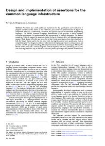
a) Ethernet Forwarding Optimized hashtable to implement a forwarding table with dleft hashing.
b) IPv4 Lookup Compressed multibit trie [10]
d) Signature Matching (DFA) c) IPv6 Lookup Two parallel pipelines for prefix DFA matching on byte streams up to 48 and one for 49 to 128. for intrusion detection. We implement D2FA compression[18] Includes two hashtables.
e) SEATTLE
f) ETHANE
Datacenterrelated: Compute Datacenterrelated: Controller shortest path between pairs of hosts build tables of all switches[8] switches [16]
Figure 7: Dataflow graphs and schedules (colors show network assignment). IPv6 page details omitted. Protocol
Mem. (MB) 2 1.4
Lines of code PLUG Ref 243 51 450 330
Logical page characterisitcs (word size, # words, code-block length) Ethernet 4 x (16, 32768, 10) IPv4 (12,1K,10) (2,17K,6) (2, 13K, 9) (14,445K,20) (2,350K,6) (2, 3584, 9) (9, 4K, 16) (2, 13K, 6) IPv6 7.2 16900 18012 (12,2K,10) (2,0,10) (4,7,10) (16,54,20) (2,188,12) (4,1027,17) (16, 7K, 20) (2, 4K, 11) (4, 22K, 11) (16, 43K, 20) (2, 49K, 12) (4, 125K, 14) (8, 3K, 12) (11, 125K, 7) (2, 392K, 7) 2 x (4, 8K, 16) 8 x (8, 8K, 13) (16, 9K, 20) (11, 48K, 10) (14, 49K, 13) (2, 181K, 13) (4, 68K, 17) (11, 67K, 10) (14, 824, 13) (2, 194K, 13) 4 x (14, 1K, 22) DFA 2.9 470 270 (8, 12800, 9) (16, 6400, 11) (2, 1.6M, 8) Seattle 2 390 347 8 x (9, 16384, 14) (16, 4096, 20) (16, 20480, 20) (8, 65536, 9) Ethane 2 1120 200 2 x (16, 16384, 21) 4 x (16, 16384, 10) 2 x (16, 16384, 10) Ethernet forwarding uses as input short packet traces captured during peak and off-peak traffic hours on the department network at our university. The table uses 100K random addresses. For IPv4 and IPv6 we constructed traces from sampled packet headers using similar techniques to those employed in the literature [7]. The routing table is constructed from 256K prefixes. For signature matching(DFA), we use a set of standard signatures from Cisco for FTP, HTTP, and SMTP protocols combined [1] (64K to 16M states). Seattle is dimensioned to support 60K switches, and for Ethane we build a flow table that can hold 16K entries using techniques proposed by its authors.
Table 3: Characteristics of the lookup objects
5.1
Methodology
As part of our prototype hardware and compiler implementation, we developed a full-chip simulator that models cores, routers, and memories. Because the architecture is statically scheduled and stall-free, the simulator is far simpler than typical microprocessor simulators. We use this simulator for the performance results and latency measurements for code-blocks, and use our tile activity-based model combined with our synthesis power estimates. Configurations: We evaluate performance on the three different PLUG configurations - 1-VT, 1-VT-L, and 4-VT-L. Our application analysis and projection for future growth suggests 4MB on-chip storage is reasonable. A 58mm2 die size for all configurations provide 37, 18, and 16 tiles respectively and storage of 2.3MB, 4.5MB, and 4MB3 . IPv6’s dataset is 7.2MB and we use a larger die size to fit the dataset. Applications: We study a diverse set of six network tasks described in Table 3. Descriptions are in their respective references. We have implemented their respective lookup 3 Due to scheduling losses, the 1-VT and 1-VT-L configurations required scaling down the dataset for this die size.
objects, and compiled them using the PLUG compiler with different chip configurations as inputs. We verified them against reference implementations by running on the PLUG simulator and directly compiling the C++ objects on Linux/x86. Figure 7a-f shows their dataflow graphs along with the schedules that are generated by our toolchain for the 4VT configuration. The schedules show which logical page is mapped to each virtual tile. The dataflow edges and the corresponding network assigned is denoted by the same color.
5.2
Results
Performance: Throughput is one lookup per cycle and is thus 1000 million decisions per second (MDPS) always. The columns in Table 4, show the total latency, activity, power, and a minimum die size for the different PLUG configurations. The total latency varies only by a few cycles from one configuration to another. This is because, the codeblock latencies are identical for all configurations and only the routing latencies vary. Overall the latencies are around 70ns with IPv6 having the largest latency because of the many logical pages. Power does not vary significantly between the configurations and power consumption is under 1 watt in all cases except IPv6.
Protocol Ethernet IPv4 IPv6 DFA Seattle Ethane
1-VT 26 98 232 45 65 47
Latency (ns) 1-VT-L 4-VT 20 18 92 90 220 219 39 37 59 57 41 39
A 1.25 2.5 14.9 0.9 5 3.2
Power(watts) 1-VT 1-VT-L 4-VT 0.24 0.27 0.23 0.36 0.44 0.35 2.4 2.4 2.3 0.27 0.43 0.27 0.66 0.66 0.63 0.42 0.45 0.41
Min. Area (mm2 ) 1-VT 1-VT-L 4-VT 57 30 30 84 72 30 486 384 240 96 57 45 111 57 45 57 30 30
Table 4: Performance on 58mm2 PLUG. Why virtual tiles? Multiple virtual tiles, while more complex, provide more usable storage and hence smaller chips. The last set of columns in Table 4 shows the minimum die size required to map an application. The 1-VT configuration devotes too much area to cores (50%) and hence requires larger dies ranging from 30 to 484 mm2 . The 1-VTL addresses this imbalance, but it suffers from scheduling losses to enforce static scheduling. The 4-VT configuration provides the smallest die sizes because it allows maximum scheduling flexibility. On average it requires a 27% less area than 1-VT-L and for applications with many pages like IPv6, it’s area is up to 37% smaller. Result: The 4-VT configuration effectively utilizes the PLUG and generates compact schedules Comparison to specialized design: We compare PLUG’s performance against best of breed specialized implementations. Ethernet forwarding requires < 40 million decisions per second, and the PLUG’s 1000 MDPS performance is unnecessary. Seattle and Ethane are recently proposed academic protocols and do not yet have specialized implementations. We show comparisons for IPv4, IPv6, and signature matching (DFA). For IPv4, Netlogic’s 55nm NLA9000 processor sustains 300 million decisions per second (MDPS) 4 , which is about 3X worse than the PLUG, at 3.5X more power. Their IPv6 performance is only slightly lower but supports a smaller table than our implementation (250K entries), For IPv6, PLUG provides 2X better performance at about 30% extra power. For signature matching we compare to Tarari’s T10 [26] which performs 1250 MDPS at 5W, outperforming PLUGs by 25% while consuming almost 10X power5 . The details of this chip are not public, but the power overhead suggests it is TCAM-based. Result: PLUGs are competitive with specialized designs and more power efficient for some. We now compare to performance results in the literature, scaling our prototype to the corresponding technology. Baboescu et al. [6] describe a memory architecture that can provide unequal memories at each pipeline stage and limited programmability to provide IP lookup, VPN forwarding and packet classification. They report performance of 166 million decisions per second (MDPS) on 90nm technology. PLUGs at 90nm, will sustain 440 MDPS. Hasan and Vijaykumar [15] propose a specialized highly scalable solution for IP lookup alone. We believe the most meaningful comparison is to their performance of 500 MDPS at 22 watts with a 1000 mm2 chip (22MB of SRAM) at 100nm technology. A 22MB PLUG chip at 100nm will be 862 mm2 , sustain 400 MDPS, and consume 11.2 watts. Kumar et al. [17] propose an IP lookup engine based on FIFOs and memories sustaining 500 MDPS at 7 watts with 90nm technology. To 4
Netlogic provides these estimates on request without NDA One “decision” on the T10 is different from one “decision” on the PLUG because of different representation of signatures. 5
support a similar 4MB table, PLUGs require a 156 mm2 chip, and will consume 4.9 watts. To summarize, the flexible PLUG design can match the performance of specialized designs because the simplicity provides efficiency.
6.
RELATED WORK
PLUGs are inspired by recently proposed tiled architectures [27, 21, 23, 25]. PLUGs address key limitations that make these existing designs ill-suited as a lookup module. TRIPS and Wavescalar support memory disambiguation, block-level register renaming, and dynamic code scheduling but are ill-suited for intense load/store processing and devote too little area to storage. RAW/Tilera’s design, while simpler, does not support sufficient throughput as discussed in Section 2. Each tile is a like a VLIW core and includes a router with flow-control, buffering, and explicit programs. Multicore processors like Cavium Octeon are similar. Similar to historical data-flow machines [4] the PLUG architecture implements dataflow execution but in a coarse granularity of code-blocks and network messages. The PLUG programming model is inspired by the SDF model [20] and has similarities to StreamIT [12]. It is more general than SDF but less general than StreamIt: specifically, stateless code-blocks and the static guarantees to provide a contentionfree network. Unlike StreamIT’s fission and fusion phases, the PLUG compiler breaks the larger logical pages into fixed size physical pages and maps them to regular memories. Code-generation because of multi-granular memory and use of intrinsics for bit-manipulation instructions is another large difference to the Streamit compiler. These specializations allowed us to simplify the architecture. Our performance comparison covered related specialized network architectures.
7.
CONCLUSIONS
In this paper, we propose pipelined lookup grids (PLUGs) as a new hybrid storage and computation model and architecture for large data structures used for lookups in network processing. PLUGs exploit the inherent structure in the lookup data-structure by physically mapping the data structure to on-chip tiled storage and associating some codeblocks with these tiles. Our results show that PLUGs are able to perform critical network processing tasks at high speeds (1 billion lookups per second with a latency of 18ns to 219ns) with limited power budgets (under 1 watt for all tasks except IPv6 for a 58 mm2 chip at 55nm). PLUGs are competitive with the best existing custom hardware designs, and provide more flexibility and programmability. We showed that the software toolchain effectively provides programmability without sacrificing performance. Implementing the ASIC chip and running live traffic will add more insight on the design and bottlenecks. While PLUGs are designed for network processing, they can po-
tentially be integrated as part of the memory hierarchy to manage irregular data structures efficiently.
8.
ACKNOWLEDGMENTS
We thank the anonymous reviewers, the Vertical group, Daniel Luchaup, and Matt Fredrikson for comments and the Wisconsin Condor project and UW CSL for their assistance. Many thanks to Mark Hill for several discussions that helped refine this work. Support for this research was provided by the National Science Foundation under the following grants: CCF-0845751, CCF-0917238, CNS-0917213 and the Wisconsin Alumni Research Foundataion. Any opinions, findings, and conclusions or recommendations expressed in this material are those of the authors and do not necessarily reflect the views of NSF or other institutions.
9.
REFERENCES
[1] Cisco intrusion prevention system. http://www.cisco.com/en/US/products/sw/secursw/ ps2113/index.html.
[2] B. Agrawal and T. Sherwood. Modeling tcam power for next generation network devices. In ISPASS, pages 120–129, 2006. [3] M. Al-Fares, A. Loukissas, and A. Vahdat. A scalable, commodity data center network architecture. In SIGCOMM ’08, pages 63–74. [4] Arvind and D. E. Culler. Dataflow Architectures. Annual Review of Computer Science, 1:225–253, 1986. [5] F. Baboescu, S. Rajgopal, N. Richardson, and L.-B. Huang. A scalable ip lookup low-power implementation for oc-768 links. In Workshop for Application Specific Processors(WASP (2004). [6] F. Baboescu, D. M. Tullsen, G. Rosu, and S. Singh. A tree based router search engine architecture with single port memories. In ISCA ’05, pages 123–133, 2005. [7] F. Baboescu and G. Varghese. Scalable packet classification. In SIGCOMM, pages 199–210, 2001. [8] M. Casado, M. J. Freedman, J. Pettit, J. anying Luo, N. McKeown, and S. Shenker. Ethane: taking control of the enterprise. In SIGCOMM, Aug. 2007. [9] L. De Carli, Y. Pan, A. Kumar, C. Estan, and K. Sankaralingam. Plug: Flexible lookup modules for rapid deployment of new protocols in high-speed routers. In SIGCOMM ’09. [10] M. Degermark, A. Brodnik, S. Carlsson, and S. Pink. Small forwarding tables for fast routing lookups. In SIGCOMM, pages 3–14, Oct. 1997. [11] S. Dharmapurikar, P. Krishnamurthy, T. Sproull, and J. Lockwood. Deep packet inspection using parallel bloom filters. In IEEE Micro, pages 44–51, 2003. [12] M. Gordon, W. Thies, M. Karczmarek, J. Lin, A. S. Meli, C. Leger, A. A. Lamb, J. Wong, H. Hoffman, D. Z. Maze, and S. Amarasinghe. A Stream Compiler for Communication-Exposed Architectures. In ASPLOS-X, pages 291–303, October 2002. [13] P. Gratz, K. Sankaralingam, H. Hanson, P. Shivakumar, R. McDonald, S. Keckler, and D. Burger. Implementation and Evaluation of a Dynamically Routed Processor Operand Network. In NOCS, May 2007.
[14] P. Gupta and N. Mckeown. Packet classification using hierarchical intelligent cuttings. In Hot Interconnects VII, pages 34–41, 1999. [15] J. Hasan and T. N. Vijaykumar. Dynamic pipelining: Making IP truly scalable. In SIGCOMM ’05, pages 205–216, 2005. [16] C. Kim, M. Caesar, and J. Rexford. Floodless in SEATTLE: A scalable ethernet architecture for large enterprises. In Proceedings of the ACM SIGCOMM, Aug. 2008. [17] S. Kumar, M. Becchi, P. Crowley, and J. Turner. CAMP: fast and efficient IP lookup architecture. In ANCS, pages 51–60, 2006. [18] S. Kumar, J. Turner, and J. Williams. Advanced algorithms for fast and scalable deep packet inspection. In ANCS 2006, pages 81–92. [19] C. Lattner and V. Adve. LLVM: A Compilation Framework for Lifelong Program Analysis & Transformation. In CGO ’04, Mar 2004. [20] E. A. Lee and D. G. Messerschmitt. Synchronous data flow. Proceedings of the IEEE, 75(9):1235–1245, 1987. [21] K. Mai, T. Paaske, N. Jayasena, R. Ho, W. J. Dally, and M. Horowitz. Smart Memories: A modular reconfigurable architecture. In ISCA ’00, pages 161–171, June 2000. [22] U. Saif, J. Anderson, A. Degangi, and A. Agarwal. Gigabit routing on a software-exposed tiled-microprocessor. In ANCS 2005, pages 51–60. [23] K. Sankaralingam, R. Nagarajan, H. Liu, C. Kim, J. Huh, S. W. Keckler, D. Burger, and C. R. Moore. Exploiting ILP, TLP and DLP with the Polymorphous TRIPS Architecture. In ISCA ’03, pages 422–433. [24] T. Sherwood, G. Varghese, and B. Calder. A pipelined memory architecture for high throughput network processors. In ISCA, pages 288–299, 2003. [25] S. Swanson, K. Michelson, A. Schwerin, and M. Oskin. Wavescalar. In MICRO 36, pages 291–302, Dec. 2003. [26] Tarari t10 product sheet, http://www.tarari.com/t10. [27] M. B. Taylor, J. Kim, J. Miller, D. W. laff, F. Ghodrat, B. Greenwald, H. Hoffman, P. Johnson, W. L. Jae-Wook Lee, A. Ma, A. Saraf, M. Seneski, N. Shnidman, V. Strumpen, M. Frank, S. Amarasinghe, and A. Agarwal. The RAW Microprocessor: A Computational Fabric for Software Circuits and General-Purpose Programs. IEEE Micro, 22(2):25–35, March 2002. [28] Xtensa lx2: The fastest processor core ever, http://www.tensilica.com/products/xtensa/lx.htm.
[29] S. Thoziyoor, N. Muralimanohar, and N. Jouppi. Cacti 5.0. Technical Report HPL-2007-167, HP Research Labs, 2007. [30] N. Tuck, T. Sherwood, B. Calder, and G. Varghese. Deterministic memory-efficient string matching algorithms for intrusion detection. In IEEE Infocom, pages 333–340, 2004. [31] H.-S. Wang, X. Zhu, L.-S. Peh, and S. Malik. Orion: a power-performance simulator for interconnection networks. In MICRO 35, pages 294–305, 2002. [32] T. Y. C. Woo. A modular approach to packet classification: Algorithms and results. In IEEE Infocom, pages 1213–1222, 2000.