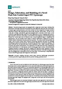
Yu-Fan Chen1 , Heng-Chuan Hsu 1, Cheng-Ping Yang2 and Tyng Liu1. 1Department of Mechanical Engineering, National Taiwan University, 10617 Taipei, ...
MATEC Web of Conferences 10 8 , 07004 (2017)
DOI: 10.1051/ matecconf/201710807004
ICMAA 2017
Design and Modeling of a Novel Torque Vectoring Differential System 1
1
2
Yu-Fan Chen , Heng-Chuan Hsu , Cheng-Ping Yang and Tyng Liu
1
1
Department of Mechanical Engineering, National Taiwan University, 10617 Taipei, Taiwan Mechanical and Systems Research Laboratories, Industrial Technology Research Institute, Hsinchu 310, Taiwan
2
Abstract. In this paper, a new concept torque vectoring differential (TVD) system is presented. It is shown that the structure and the mechanism of the system, the operating methods, and the parameters design by a simulation program, i.e. SimulationX. First of all, the structure of the new TVD system is introduced, as well as the relevant mechanic equations. Second, we attempt to verify the feasibility and accuracy of SimulationX through establishing a simple mechanical model by MATLAB, so that the further modeling and simulation results of the new TVD system will be credible. Then, the simulation results at the setting conditions are presented. Finally, the sensitivity of the design parameters is analyzed, including adjusting the braking torque and the dimensions of the gear sets in the differential. According to these results, the characteristics of the new TVD system can be derived in order to develop the whole system with vehicle dynamic model in the next stage.
1 Introduction Of all vehicle dynamics, such as steering and braking system, are in pursuit of driving performance and safety. In vehicle stability system, torque vectoring is a new technology that has advanced most rapidly in recent years. In order to prevent vehicle accidents, vehicle dynamics control are widely developed and used since the 1980s [1]. For examples, direct yaw moment control (DYC) [2], electronic stability program (ESP) [3, 4], and traction control system (TCS) are control strategies for improving vehicle stability. In general, these control strategies adjust vehicle dynamics through braking system. However, there may be an enormous power loss due to brakes. Therefore, torque vectoring differential (TVD) [5] is proposed to solve the power loss issue and provided to adjust torque distribution. A torque vectoring differential is a system based on a conventional differential gear, and it is usually connected with one or more of different ratio speeds and clutches (or brakes) that can transfer input torque efficiently and direct the power flow separately into wheels while a vehicle is in acceleration or cornering. Torque vectoring differential is now a popular system and several different types of torque vectoring differential are invented by automobile companies such as Mitsubishi [6], Audi [7], and Honda [8]. However, in most current torque vectoring differentials, issues of structural complexity, space requirement, development cost, etc. are still high. Hence, with a simple structure, limited space, and low cost, a novel design of torque vectoring differential based on a conventional differential gear is proposed in this research.
2 Design and modeling In this section, a new differential gear possesses torque vectoring differential function is proposed. Its mechanism and dynamics are introduced and analyzed, and then the mathematical form is derived. Before modeling the new TVD system, models of a conventional differential gear are established by SimulationX and MATLAB, and simulated results are also compared for verification. 2.1 New differential gear design 2.1.1 Function of torque vectoring differential The new TVD system provided in this paper integrates the gear sets, actuator units, and required control methods. The main structure is shown in Fig. 1. It is a new concept differential with additional torque vectoring gears. This structure includes the outer and inner differential gears which are fixed with center pin; two side gears are connected with each output shaft; two torque vectoring gears which are concentric with each output shaft, and each of them stretches out of the differential case connecting with the brake. In order to transfer torque from one side to the other side of the wheel, based on the tire model and the slip ratio model, the rotational speed of the wheel should be adjusted actively. To this new TVD system, it is easy to adjust the rotational speed of the output shafts by operating the brakes. For example, if the right-side output shaft needs to be accelerated, we can operate the left brake generating a braking torque into the left-side gear.
© The Authors, published by EDP Sciences. This is an open access article distributed under the terms of the Creative Commons Attribution License 4.0 (http://creativecommons.org/licenses/by/4.0/).
MATEC Web of Conferences 10 8 , 07004 (2017)
DOI: 10.1051/ matecconf/201710807004
ICMAA 2017 �I �0 � �0 � �0 �0 � �0 �R � 4 � R4 � �r � r
Then, the rotational speed of the left-side output shaft will decrease. On the contrary, the rotational speed of the right-side output shaft will increase. As a result, the drive torque will transfer from left-side output shaft to rightside output shaft. Outer differential gear
Center pin
Inner differential gear
Case
Torque vectoring gear Side gear
0
0
0
0
0
�r
r
R4
I1
0
0
0
0
r
0
0
0
I2
0
0
0
0
�r
0
0
0
I3
0
0
r3
r3
R3
0
0
0
I4
0
0
0
� R4
0
0
0
0
I4
0
0
0
0
0
R3
� R4
0
0
0
0
0
0
� R3
0
� R4
0
0
0
�r
0
�r3
0
0
0
0
0
0
�r
r3
0
0
0
0
0
R4 � �� � � T � 0 �� �1 �� �T1 0 ��2 � �T2 � � � R3 ��3 � 0 (11) � � 0 � 0 � 4 � � � R4 ��5 � �Tb � � 0 F 0 � 1 � 0 � F2 � 0 � � 0 � F3 � 0 � � 0 � F4 � 0 �
Output shaft
2.2 SimulationX-based multi-physical model 2.2.1 Introduction to SimulationX SimulationX is a multi-physics tool that can establish a three-dimensional model for dynamic simulation through physical modeling, signal modeling, and equation-based modeling. One of the advantages of SimulationX is to build a model by intuition, which means it is not necessary to derive equations for programming. For example, by using and connecting built-in modules from Table 1, then a diagram and three-dimensional view of a conventional differential gear model are established (Fig. 3 and Fig. 4). After an external force or torque is defined and applied, the kinematic and kinetic results of each component (module) can be calculated and measured by simulation. Fig. 5(a) shows an input torque applied on the case, and rotational speed and angular acceleration of the output wheels are shown in Fig. 5(b) and Fig. 5(c). The curves of right and left shafts are identical because the loading torque on each side is the same, which means there is no speed difference.
Figure 1. Schematic diagram of new TVD system.
2.1.2 Dynamic force analysis According to the diagram in Fig. 2, equation of motion of each component can be derived as follows. Eq. (1) represents the motion of the case, Eq. (2) and (3) represent the motion of the wheels, Eq. (4) to (6) represent the motion of the gears, and Eq. (7) to (10) represent the differential of tangential velocity of the gear contacts. Therefore, a 10 x 10 matrix of the new TVD system is formed.
Table 1. Modules in SimulationX software. Symbol
Description This element type models a cuboid
Figure 2. Free body diagram of new TVD system.
T � F1r � F2 r � F3 R3 � F4 R4 � I �
(1)
� F1r � T1 � I1�1
(2)
T � F1r � F2 r � F3 R3 � F4 R4 � I �
(3)
�F1r3 � F2 r3 � F3 R3 � F4 R3 � I3�3
(4)
F3 R4 � I 4�4
(5)
F3 R4 � Tb � I 4�5
(6)
�4 R4 � � R4 +�3 R3
(7)
�5 R4 � � R4 � �3 R3
(8)
�1r � �r � �3 r3
(9)
�2 r � �r � �3 r3
(10)
This element type models a hollow cylinder This element type models a revolute joint with rotation around a selectable axis This element type models an external teeth gearwheel This element type models an interface element with two mechanical connectors connectable to rotational elements This element type models a body torque This signal block permits the generation of signals from sampled data
2
MATEC Web of Conferences 10 8 , 07004 (2017)
DOI: 10.1051/ matecconf/201710807004
ICMAA 2017
(c) Angular acceleration of the two wheels. Figure 5. SimulationX simulation results of the conventional differential gear.
2.2.2 Verification by MATLAB programming In this part, the previous SimulationX simulation results of the conventional differential gear model will be verified by MATLAB programming. Figure 6 shows a conventional differential gear connected with one shaft and two wheels. An input torque is applied on the shaft, and the two wheels are considered as outputs. Therefore, a mathematical matrix form can be derived as follows.
Figure 3. Model of a conventional differential gear.
Figure 4. Structure of a conventional differential gear. Figure 6. Free body diagram of a conventional differential gear .
In MATLAB programming, all of the parameter values such as the inertia of the carrier and the powertrain Ic, the inertia of each wheel Iw, and the input torque τc are the same in the SimulationX model. Comparing these two simulation results, the curves illustrated by MATLAB in Fig. 7 nearly matches the curves illustrated by SimulationX in Fig. 5. Thus, it can be verified that SimulationX is a useful tool as MATLAB. Moreover, SimulationX enables to establish a multi-physical model to check design parameters such as size, position, and shape in three-dimensional space. It is more visual and sensible to perceive directly through human eyes. Therefore, analysis of the new TVD system is based on SimulationX software, and the simulated results will be discussed in next section.
(a) Input torque applied on the gear case.
(b) Rotational speed of the two wheels.
3
MATEC Web of Conferences 10 8 , 07004 (2017)
DOI: 10.1051/ matecconf/201710807004
ICMAA 2017 wheels (I1 and I2), whereas the shafts fixed the torque vectoring gears are able to be connected to brakes or clutches. All of them are rotating with respect to the same rotational axis but these shafts have a relative angular displacement that can be rotated in different rotational speed. Table 2 shows detailed values of parameters in the new TVD system simulation.
(a) Input torque applied on gear case.
(b) Rotational speed of the two wheels.
(c) Angular acceleration of the two wheels. Figure 7. MATLAB simulation results of the conventional differential gear.
Figure 8. Model of new TVD system.
3 Simulation results In this section, SimulationX is used to establish a threedimensional structural model of the new TVD system, and the braking torque is applied to analyze the characteristics of the torque vectoring function. Then, various combinations of the parameter values are selected to observe the variation in the speed of right and left wheels. Therefore, the torque vectoring performance can be determined.
Figure 9. Structure of new TVD system. Table 2. Parameter value settings in the simulation. Parameters
3.1 Simulation setup
Inertia of the carrier and powertrain I (kg·m2)
3.1.1 Three-dimensional structural model According to the schematic diagram of the new TVD system (Fig. 1), a prototype model of a diagram and three-dimensional view by using SimulationX is established as shown in Fig. 8 and Fig. 9. The new TVD system is composed of a conventional differential gear sets as two side gears and an inner differential gear (r and r3). Besides, there are additional outer differential gear and torque vectoring gears (R3 and R4) in the case. The output shafts fixed the side gears are represented as
4
Value 2
Inertia of each wheel I1, I2 (kg·m2)
0.1
Inertia of the outer differential gear I3 (kg·m2)
0.01
Inertia of each torque vectoring gear I4 (kg·m2)
0.01
Radius of each side gear r (m)
0.032
Radius of the inner differential gear r3 (m)
0.025
Radius of the outer differential gear R3 (m)
0.05
MATEC Web of Conferences 10 8 , 07004 (2017)
DOI: 10.1051/ matecconf/201710807004
ICMAA 2017 Radius of each torque vectoring gear R4 (m)
3.2.1 Changing parameter Tb, R3, and R4
0.041
Input torque T (N·m)
300
Loading torque of each wheel T1, T2 (N·m)
10
Braking torque Tb (N·m)
20
In order to understand the torque vectoring performance, different design parameters are changed. Therefore, the rotational speed and angular acceleration differences between the wheels are meaningful to determine the most important parameter to affect the torque vectoring performance. In this simulation, the model and initial parameter values are the same as the previous subsection. The parameters analyzed here include the braking torque Tb, the radius of the outer differential gear R3, and the radius of the torque vectoring gear R4.
(a) Input torque and braking torque.
(a) Rotational speed of the two wheels.
(b) Rotational speed of the two wheels.
(b) Angular acceleration of the two wheels. Figure 11. Change Parameter Tb.
(c) Angular acceleration of the two wheels. Figure 10. Characteristics of new TVD system.
3.1.2 Characteristics of New TVD system In the dynamic simulation, an input torque is applied on the case, vehicle loading is represented as torque loadings applied on wheels, and a braking torque is applied on left side of the outer gear shaft. In Fig. 10(a), the input torque is applied from 0 N·m to 300 N·m in 0.3s, whereas the braking torque is applied by 20 N·m after 0.1s. The curves in Fig. 10(b) and Fig. 10(c) show there are rotational speed and angular acceleration differences between right and left wheels after the braking torque is applied. According to the simulation results, the new TVD system has the ability to transfer the torque power from one side to the other side, which means the new TVD system possesses torque vectoring characteristics.
(a) Rotational speed of the two wheels.
(b) Angular acceleration of the two wheels. Figure 12. Change Parameter R3.
3.2 Sensitivity analysis
5
MATEC Web of Conferences 10 8 , 07004 (2017)
DOI: 10.1051/ matecconf/201710807004
ICMAA 2017 backlash and viscous friction will be taken into consideration.
4 Conclusions This paper presents a new TVD system. A mathematical matrix form is derived, and a three-dimensional structural model is established, and a dynamic performance is illustrated based on the SimulationX multi-physics model. The simulation results demonstrate the torque vectoring capability and of the new TVD system that can transfer the torque power from one side to the other side while a braking torque is applied. In characteristics of sensitivity analysis, changing the braking torque is more efficient to affect the torque vectoring performance than changing the radius of the outer differential gears. As a result, a control strategy by engaging the braking torque is more effective way to distribute torque power on wheels, whereas the size of the new TVD system can be smaller due to its less sensitivity to dimension.
(a) Rotational speed of the two wheels.
(b) Angular acceleration of the two wheels. Figure 13. Change Parameter R4.
References 1.
3.2.2 Discussions 2.
In changing the braking torque, Tb is set to be 0, 20, and 40. Figure 11 shows there is no speed difference between wheels while it is without braking torque, whereas the rotational speed of the left wheel is decreased immediately after the braking torque intervenes. The larger braking torque, the more speed dropped on the left wheel. In changing the radius of the outer differential gear, R3 is set to be 0.03, 0.04 and 0.05, and the braking torque Tb is reset to 20. Figure 12 also shows dropped speed of the left wheel, however, there is no much difference while changing the parameter R3. In addition, the similar simulated results can be observed while changing the parameter R4 (Fig. 13).
3.
4.
5. 6.
7. 3.2.3 Future work The future work is to establish a whole vehicle model equipped with the new TVD system which is able to see the effect of the torque vectoring in vehicle dynamics simulation. In addition, important factors such as
8.
6
Y. Shibahata, K. Shimada, and T. Tomari, Vehicle System Dynamics, Vol. 22, pp.465–481. (1993) Geng, C., Mostefai, L., Denai, M. and Hori, Y., IEEE Transactions on Industrial Electronics, Vol. 56, pp. 1411–1419. (2009) Yim, S., Park, Y. and Yi, K., International Journal of Automotive Technology, Vol. 11, pp. 147–153. (2010) Furukawa, Y., Yuhara, N., Sano, S., Takeda, H. and Matsushita, Y., Vehicle System Dynamics, Vol. 18, pp. 151–186. (1989) J. Park and W. Kroppe, SAE Technical Paper 200401-2053. (2004) T. Miura, Y. Ushiroda, K. Sawase, N. Takahahi, and K. Hayashikawa, Mitsubishi Motors technical review, pp. 23-26. (2008) N. Mohd Zainal Abidin, S. Imamori and A. Alexander, SAE Technical Paper 2015-01-1098. (2015) L. Kakalis, A. Zorzutti, F. Cheli and G. Travaglio, SAE Int. J. Passeng. Cars - Mech. Syst. 1(1):514-525. (2009)