IOP Conference Series: Materials Science and Engineering
PAPER • OPEN ACCESS
Design and optimize of 3-axis filament winding machine To cite this article: Ma Quanjin et al 2017 IOP Conf. Ser.: Mater. Sci. Eng. 257 012039
View the article online for updates and enhancements.
This content was downloaded from IP address 191.101.89.124 on 02/11/2017 at 01:42
4th International Conference on Mechanical Engineering Research (ICMER2017) IOP Publishing IOP Conf. Series: Materials Science and Engineering 257 (2017) 012039 doi:10.1088/1757-899X/257/1/012039 1234567890
Design and optimize of 3-axis filament winding machine Ma Quanjin*, M R M Rejab, M S Idris, D Bachtiar, J P Siregar, M N Harith Structural Materials & Degradation Focus Group, Faculty of Mechanical Engineering, Universiti Malaysia Pahang, 26600 Pekan, Pahang, Malaysia *Corresponding author:
[email protected] Abstract. Filament winding technique is developed as the primary process for composite cylindrical structures fabrication at low cost. Fibres are wound on a rotating mandrel by a filament winding machine where resin impregnated fibres pass through a pay-out eye. This paper aims to develop and optimize a 3-axis, lightweight, practical, efficient, portable filament winding machine to satisfy the customer demand, which can fabricate pipes and round shape cylinders with resins. There are 3 main units on the 3-axis filament winding machine, which are the rotary unit, the delivery unit and control system unit. Comparison with previous existing filament winding machines in the factory, it has 3 degrees of freedom and can fabricate more complex shape specimens based on the mandrel shape and particular control system. The machine has been designed and fabricated on 3 axes movements with control system. The x-axis is for movement of the carriage, the y-axis is the rotation of mandrel and the z-axis is the movement of the pay-out eye. Cylindrical specimens with different dimensions and winding angles were produced. 3-axis automated filament winding machine has been successfully designed with simple control system.
1. Introduction Composite materials are increasingly used in the civil infrastructure and piping system to transport sewage, service and potable waters [1]. Because of light weight, high specific strength, stiffness, fatigue characteristics and better corrosion resistance. In the last decade, the use of filament wound composite materials has drastically increased. Filament wound composites have been replaced metal alloys in many applications, for example, the high-pressure vessel in chemical plant or aeronautical/space vehicles, or transportation tubes in oil, gas and nuclear industries [2, 3]. Until now more researchers have researched the experimental and investigations on filament wound GRP pipes, filament wound GERP and CFRP composite tubes. Different kinds of composite materials have processed specific mechanical properties by previous researchers [4]. The filament winding process is a low cost, efficient and relative maturity manufacturing process, which generally used in the mass production of fibre reinforced composite components [5]. Filament winding method is the most broadly used fabrication process to produce rotational symmetry [6]. This process can be accomplished in two different ways as reciprocal or continuous method [7]. Continuous filament winding is the simple and sufficient method to fabricate a fibre reinforcement structures, a continuous band of reinforcement is impregnated with resin and then wound over a rotating mandrel [8, 9]. The reinforced fibres are usually made of glass, kevlar or carbon. Owing to a simplicity of manufacturing process, the hardware involves two main sub-systems, which is the rotary assembly and the delivery system[10].
Content from this work may be used under the terms of the Creative Commons Attribution 3.0 licence. Any further distribution of this work must maintain attribution to the author(s) and the title of the work, journal citation and DOI. Published under licence by IOP Publishing Ltd 1
4th International Conference on Mechanical Engineering Research (ICMER2017) IOP Publishing IOP Conf. Series: Materials Science and Engineering 257 (2017) 012039 doi:10.1088/1757-899X/257/1/012039 1234567890
2. Review on the filament winding process 2.1 Winding Methods 2.1.1 Wet winding. There are two different winding methods, which are wet and prepreg winding. Wet winding, in which the fibres are passed through a resin bath and wound onto a rotating mandrel. This type of low-cost system is generally used in commercial applications with polyester and epoxy resins. The resin field is affected by several parameters: resin viscosity, the squeeze rollers, winding tensioner, the number of layers, etc [11]. Figure 1 shows the wet winding method general view. Compared to prepreg winding, wet winding has several main advantages: short processing time; low costs about the composite material, simple resin formulation model which can be easily selected to meet the specific needs in different severe working condition, convertibility of resin system which can be transformed.
Figure 1. Wet winding method. 2.1.2 Prepreg winding. This winding method is shown in Figure 2. Prepreg winding, in which the preimpregnated fibre tows are placed on the rotating mandrel [12]. Pre-impregnated rovings offer excellent quality control and reproducibility in contents, bandwidth and uniformity. These parameters can be well satisfied with the filament winding process. On the factory experiment laboratory, many quality control tests can be done for prepreg winding. The obvious advantage of the prepreg is better resin content control, due to the protection supplied by the resin and more consistent composite properties reduce the fibre tows damage. The general shortcomings of prepreg are poor surface layer availability, higher costs and without room temperature as possible.
Figure 2. Prepreg winding method [11]. 2.2 Winding pattern There are basically three types of winding patterns: circumferential, helical, and polar winding. 2.2.1 Circumferential winding. It is known as the hoop or circumferential winding, Generally speaking, circumferential winding is a special winding angle which attains 90 degrees of winding angle. Each full rotation of the mandrel advances the carriage by full bandwidth as shown in Figure 3.
2
4th International Conference on Mechanical Engineering Research (ICMER2017) IOP Publishing IOP Conf. Series: Materials Science and Engineering 257 (2017) 012039 doi:10.1088/1757-899X/257/1/012039 1234567890
Figure 3. Circumferential or hoop winding [12]. 2.2.2 Helical winding. In the helical winding, mandrel rotates at a constant speed while the carriage unit transverses back and forth at a regular speed, the composite fibre is taken out by mandrel rotation force from ring pay-out eye or delivery system. It has been shown in Figure 4. To control the rotation speed and carriage speed, the desired winding angle can be fabricated.
Figure 4. Helical winding [14]. 2.2.3 Polar winding. In polar winding, which is shown in Figure 5. Composite fibres pass tangentially to the polar position and cover the fibre along the polar path, reverses direction, and passes tangentially to the opposite polar position at the other end. In one word, composite fibres are wound from one pole to pole, while the mandrel arm rotates around the longitudinal axis. Polar winding needs a high degree of freedom machine to execute.
Figure 5. Polar winding [14]. 2.3 Materials of Fabrication Filament winding requires continuous fibre reinforcement and a resin system to stick together and fabricate desired composite material. There are various types of fibre reinforcement that can be impregnated with a resin matrix. Reinforcing fibres for polymer-matrix composites are commonly glass, graphite and aramids. The fibre characteristics have affected the stiffness and the strength of the composite material performances. Table 1 shows a brief comparison of carbon reinforcements. The main fibres are summarised below: a) Glass: glass fibres are the most commonly used and the least expensive of all fibres. The composite material is called glass-fibre reinforced plastic (GFRP) and it may contain between 30% and 60% glass fibre by volume[15]; 1) E type: a calcium alumni borosilicate glass-good tensile strength, low tensile modulus, lowest cost fibre, generally used in commercial and industrial products, commonly used in filament winding;
3
4th International Conference on Mechanical Engineering Research (ICMER2017) IOP Publishing IOP Conf. Series: Materials Science and Engineering 257 (2017) 012039 doi:10.1088/1757-899X/257/1/012039 1234567890
2) S type: magnesia-aluminosilicate glass-applying high tensile strength and stiffness but at greater cost, used in aerospace and high-performance pressure vessel; b) Aramids: higher tensile strength, higher tensile modulus, high cost, low density, excellent impact and damage tolerance properties. c) Carbon fibre: The properties of carbon fibres, such as high stiffness, high tensile strength, low weight, high chemical resistance, high-temperature tolerance and low thermal expansion. When combined with a plastic resin and wound or moulded it forms the carbon-fibre-reinforced polymer (often referred to as carbon fibre) which has a very high strength-to-weight ratio, and is extremely rigid although somewhat brittle. Table 1. Comparison of fibre reinforcements[13]. Reinforcement E-glass
Density/Kg/m3
Tensile strength/Mpa
Tensile modulus/GPa
3447 a
2547
72.4
2758 b S-glass
4585 a
2491
85.5
3792 b Carbon(AS4)
1799
3998
231
Kevlar 49(Aramids)
1449
2758
131 a
Monofilament bStrand
3. Methodology Research methodology in this project can be simply divided into three phases: Phase 1: Literature review and purchase necessary components i. It is essential that we should figure out identification of objectives, methods, potential problems and sufficient knowledge about filament winding manufacturing technique. ii. It is a effective method to purchase the material and equipment structure, parameters and applications. Phase 2: Design a 3-axis filament winding machine and optimize processing capability i. Compared to previously related machine structure, start the preliminary design of the 3-axis lathe-type filament winding machine. ii. Essential process is that a simple, stable, efficient control system should be designed, which includes different kinds of microcontrollers are more suitable for target machine structure. It spends much time on comparing the strengths and weaknesses. Phase 3: Fabricate filament wound composite cylinders i. Based on the test and check the control system of the machine, send the specific codes to fabricate cylindrical structures in different winding angles, which range from 0° to 90°. 3.1 Problem identification and solution All steps in the engineering design process, so it is most important to give a problem definition. Figure 6 shows the basic progress in this project. This design project is to design a 3-axis filament winding machine and optimise it, then enhance the machine performance that can fabricate the desired product, which on account of costs and customer requirements. Based on the previous design of filament winding machine [16], 3-axis filament winding machine design concepts and methods are clear-cut in
4
4th International Conference on Mechanical Engineering Research (ICMER2017) IOP Publishing IOP Conf. Series: Materials Science and Engineering 257 (2017) 012039 doi:10.1088/1757-899X/257/1/012039 1234567890
principle. Design concepts are the methods for machine function, which include the rotation unit, carriage unit, ring pay-out eye unit, control system unit, resin bath, machine structure, tensioner, comb device, mandrel and etc.
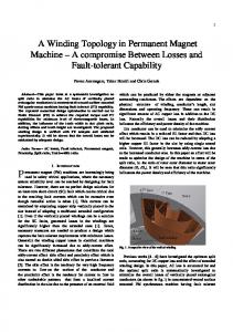
Figure 6. Basic progress in the design process. 4. Design and optimize 3 axes machine Schematic layout of proposed 3-axis filament winding machine, which can be divided into four main units: the rotary unit, the carriage unit, the ring pay-out eye unit and the control system unit. Based on those main units, the machine prototype can gradually be designed. Other necessary components should be completed after the machine prototype is accomplished step by step. The 3-axis filament winding machine optimises design process includes the lead screw, resin bath, comb device and other components. The optimization process focuses on improvements about 3-axis filament winding machine processing capability. 4.1 The rotary unit Figure 7 shows the machine rotary unit front view and left view. Like other common filament winders, the rotary unit consists of two basic blocks. Of the two blocks, one is fixed and can simply be removed, the other is mandrel rotation, which can be under controlled. It has many kinds of mandrels, the mandrel in this project is chosen as a 38mm diameter, 690mm length hollow mandrel, which is made of aluminium alloy material. It can support the burden on stepper motor y loading. The mandrel is held on the horizontal line by two mandrel holders, which are printed via 3D Printer Machine. Inside the mandrel, a stainless steel rod is designed to hold the mandrel and mandrel holders, which can prevent the mandrel holders from bending. Between the mandrel and mandrel holders, the rubber ring is put on the contact area, which will effectively enhance the mandrel cylindricity and horizontal extent, rubber ring can reduce vibration impact for composite cylinders when mandrel rotates. Figure 7 shows the rotary unit design drawing. The rotation process is optimized by modification on process stabilization, stepper motor position and proper belt pully parameters.
Figure 7. The rotary unit front view and left view.
5
4th International Conference on Mechanical Engineering Research (ICMER2017) IOP Publishing IOP Conf. Series: Materials Science and Engineering 257 (2017) 012039 doi:10.1088/1757-899X/257/1/012039 1234567890
4.2 The carriage unit The carriage unit mainly consists of the tensioner, composite fibres creels, resin bath, two guide bars, stepper motor x, and comb device. The carriage unit is driven by a reversible stepper motor x, which transfers constant speed to carriage frame via belt holder fixed in carriage base. The tensioner has put beside the composite fibres creels, the tension force can be controlled by turning the screw to reduce the interval between the tensioner and lever. The comb device is designed to fabricate more than one kind of composite fibre. And two carbon fibre rods can remove redundant resins, the distance can be adjusted by twisting the screw. At last, it still has another carbon fibre rod, which belongs to the transmission device, can guide composite fibre to the ring pay-out eye unit. Figure 8 shows the carriage unit final design drawing. The carriage process is optimized by modification on movement stabilization, x belt pully levelness, appropriate limit switch position, comb device structure and resin bath configuration.
Figure 8. The carriage unit back view and right view.
4.3 The ring pay-out eye unit The ring pay-out eye unit is one portion of the delivery system, which controlled by stepper motor z. The shape of pay-out eye unit is a ring or circular, a straight bar is put to guide fibres closely to the mandrel. The ring pay-out eye is fixed on the carriage unit by four square holders, which put four bearings into ring inside a slot. It can make the ring pay-out eye and the straight bar rotation in the meantime when the stepper motor z rotates. Based on the design concept, the straight bar rotates a certain angle clockwise or counterclockwise. Figure 9 shows the ring pay-out eye unit front view and left view structure. It is a highlighting unit compared to traditional delivery system design ideas. The ring pay-out eye unit has some advantages, such as maximum precision in control of bandwidth and density, good for the high angle or circular windings and good for wide bandwidth. During the carriage unit reaches a point of return, the ring pay-out eye unit just needs to rotate a certain angle clockwise or counter-clockwise. The ring pay-out eye unit process is optimized by modification on rotation stabilization, z belt pully framework, pay-out eye rotation angle, comb device structure and resin bath configuration.
Figure 9. The ring pay-out eye unit front view and left view.
6
4th International Conference on Mechanical Engineering Research (ICMER2017) IOP Publishing IOP Conf. Series: Materials Science and Engineering 257 (2017) 012039 doi:10.1088/1757-899X/257/1/012039 1234567890
4.4 The control system unit The control unit consists of Arduino Uno, CNC v1 shield, voltage regulator, Bluetooth module, power plug, DC brushless fan and limit switch. The main modules in control system are Arduino Uno and CNC v1 shield, which are connected with pins. CNC v1 shield pins are put on the back panel, which exactly connected with Arduino Uno pins. The CNC v1 shield is set above the Arduino Uno module, which cannot be drawn in the schematic diagram. Figure 10 shows other modules connection.The Bluetooth module receives the signal and sends commands to Arduino Uno to control the stepper motor x, y, and z through CNC shield. The voltage regulator transforms 220V to 35V. The power plug is a device that allows electrically operated equipment to be connected to the primary alternating current (AC) power supply in a building. DC brushless fan cools the temperature when control system works. The control system unit is optimized by modification on wire connection, stable signal transmission, the control system box position and resin protection.
Figure 10. Control system schematic diagram for the 3-axis filament winding machine.
5. Final design scheme Based on the above main concepts units, 3-axis filament winding machine has been mainly completed. It is even necessary to optimise some subsystem and devices, some components need to change the size and position, such as limit switch holder position, the control system box, comb device, tensioner and so on. Figure 11 shows the schematic diagram for proposed winding machine. The contrivable machine approach to our initial idea by means of the optimisation process, 3-axis filament winding machine only has few improvements for diversified devices to meet the needs in the future. Figure 12 shows the filament winding machine with 3-axis of winding system.
Figure 11. Schematic diagram for proposed a 3-axis filament winding machine.
7
4th International Conference on Mechanical Engineering Research (ICMER2017) IOP Publishing IOP Conf. Series: Materials Science and Engineering 257 (2017) 012039 doi:10.1088/1757-899X/257/1/012039 1234567890
Figure 12. The 3-axis filament winding machine with inexpensive control system.
5.1 Specimen fabrication When we tested the machine movement capability, it had some problems with uploading commands to Arduino Uno control system. After we solved the matters, the 3-axis filament winding machine can fabricate the filament wound composite cylinders. Figure 13 shows specimen by this machine.
Figure 13. Specimen cylinder with carbon fibre and epoxy.
6. Conclusions This research project was successfully designed, a 3-axis automated winding machine system was designed via Arduino Uno and CNC shield module. By means of controlling the spindle speed and carriage separately, the helical winding pattern with adjustable winding angle has been basically produced. Some specimens have been made to test this new winding system. The results obtained were relatively satisfactory and improved compared to the previous 2-axis or 4-axis machine. From the specimens fabricated, it concludes that the defect in surface finish is due to several main factors. Firstly, surface finish is directly proportional to steering gear from a distance. By increasing steering gear the distance, the surface finish becomes poor. Secondly, winding angle also affects the surface finish. The higher winding angle provides a better surface finish. Lastly, movement vibration also affects the quality extent of surface finish, especially for the carriage movement. Due to many limitations of this research project, some problems in the main structure have not been solved, Therefore, the specimen fabricated does not perform some experiments to measure the mechanical performance of the cylindrical structure under static compression loading. Acknowledgements The authors are grateful to the Ministry of Higher Education and Universiti Malaysia Pahang (www.ump.edu.my) for funding this research with FRGS/1/2014/TK01/UMP/02/3 and RDU1603108.
References [1] [2]
R. Rafiee 2013 "Experimental and theoretical investigations on the failure of filament wound GRP pipes," Composites Part B: Engineering, vol. 45, pp. 257-267. G. Perillo, R. Vacher, F. Grytten, S. Sørbø, and V. Delhaye 2014 "Material characterisation and failure envelope evaluation of filament wound GFRP and CFRP composite tubes," Polymer Testing, vol. 40, pp. 54-62.
8
4th International Conference on Mechanical Engineering Research (ICMER2017) IOP Publishing IOP Conf. Series: Materials Science and Engineering 257 (2017) 012039 doi:10.1088/1757-899X/257/1/012039 1234567890
[3] [4]
[5]
[6]
[7]
[8] [9]
[10] [11] [12]
[13]
[14] [15] [16]
M. Gascons i Tarrés 2011 "Assessment of virtual design and manufacturing techniques for fibre reinforced composite materials." E. V. Rojas, D. Chapelle, D. Perreux, B. Delobelle, and F. Thiebaud 2014 "Unified approach of filament winding applied to complex shape mandrels," Composite Structures, vol. 116, pp. 805-813. X. Jia, G. Chen, Y. Yu, G. Li, J. Zhu, X. Luo, et al. 2013 "Effect of geometric factor, winding angle and pre-crack angle on quasi-static crushing behavior of filament wound CFRP cylinder," Composites Part B: Engineering, vol. 45, pp. 1336-43. S. Koussios, O. Bergsma, and A. Beukers 2006 "Filament winding: kinematics, collision control and process optimisation through application of dynamic programming," Composites Part A: Applied Science and Manufacturing, vol. 37, pp. 2088-2104. M. S. Babu, G. Srikanth, and S. Biswas, 2007 "Composite fabrication by filament winding-An insight," Technology Information, Forecasting, and Assessment Council. Available: http://www. tifac. org. in/news/pub. htm. M. Lossie and H. Van Brussel 1994 "Design principles in filament winding," Composites manufacturing, vol. 5, pp. 5-13. S. Mutasher, N. Mir-Nasiri, and L. C. Lin 2012 "Small-scale filament winding machine for producing fiber composite products," Journal of Engineering Science and Technology, vol. 7, pp. 156-168. F. Abdalla, S. Mutasher, Y. Khalid, S. Sapuan, A. Hamouda, B. Sahari, et al. 2007 "Design and fabrication of low cost filament winding machine," Materials & design, vol. 28, pp. 234-239. D. B. Miracle, S. L. Donaldson, S. D. Henry, C. Moosbrugger, G. J. Anton, B. R. Sanders, et al. 2001 ASM handbook vol. 21: ASM international Materials Park, OH, USA. M. Rejab, K. Kadirgama, M. Noor, M. Sani, and R. Daud 2008 "Modification and Testing of Four Axes Filament Winding Machine," in International Conference on Science & Technology: Application in Industry & Education. J. Kim, T. J. Moon, and J. R. Howell 2003"Transient thermal modeling of in-situ curing during tape winding of composite cylinders," TRANSACTIONS-AMERICAN SOCIETY OF MECHANICAL ENGINEERS JOURNAL OF HEAT TRANSFER, vol. 125, pp. 137-146. N. Hancox 1981 Fibre composite hybrid materials: Applied Science. S. Kalpakjian and S. R. Schmid 1996 "Manufacturing engineering and technology, 2001," φ13mm W, vol. 7, pp. 340-368. S. T. Peters, W. D. Humphrey, and R. F. Foral 1991 Filament winding composite structure fabrication: SAMPE International Business Office.
9