Sep 21, 2005 - low-range LTCC force sensors down to ideally 10 mN, together with ... technology has led in our laboratory to the development of a simple ...
XXIX International Conference of IMAPS Poland Chapter Koszalin-Darłówko, 19-21 September 2005 POLAND
Design and processing of low-range piezoresistive LTCC force sensors Hansu BIROL, Marc BOERS, Thomas MAEDER, Giancarlo CORRADINI, Peter RYSER Laboratoire de Production Microtechnique, Ecole Polytechnique Fédérale de Lausanne (EPFL) BM3.142, Station 17, CH-1015 Lausanne, Switzerland Abstract: Low-temperature cofired ceramic (LTCC) combines many advantageous features for lowrange (force & pressure) piezoresistive sensors: ease of 3D structuration, availability of very thin sheets, low elastic modulus and yet reasonable mechanical strength. This work covers the design and fabrication low-range LTCC force sensors down to ideally 10 mN, together with mechanical characterisation of LTCC substrates. We show that LTCC is a viable substrate for piezoresistive sensing, and that 3D structuration can be used to both increase the output signal and simplify production. Moreover, very sensitive LTCC sensors may be manufactured, provided specific thick-film conductors with a sintering behaviour closely matched to that of the LTCC are applied. Key words: thick-film force sensors, LTCC.
1. INTRODUCTION Thick-film piezoresistive force and pressure sensors, using appropriate resistive compositions as sensitive materials, have found wide application in industry due to their simplicity, low cost and reliability 0. This technology has led in our laboratory to the development of a simple generic force sensor design (figure 1, 0.4 to 2.0 N force ranges), where a sensing beam is soldered onto a mechanical base, which also carries the amplification electronics. In almost all cases, the standard 96% alumina used as a substrate material for thick-film electronics is also used for the sensor elastic element, in spite of its moderate strength and high elastic modulus For (very) low range force sensing, which is the object of this paper, classic alumina substrates have other drawbacks: − Scoring and breaking (the standard thick-film individualisation procedure) is not practical at very small dimensions, while laser cutting severely degrades the mechanical properties 0. Moreover, very thin alumina substrates are very fragile and therefore difficult to handle, or not available at all. − While solder assembly is reasonably reliable 0, it creates parasitic stresses 0. Placement of the sensing resistors is therefore a compromise between maximising signal (placement near the solder joint) and minimising parasitic stresses (placement away from the joint). − The nominal displacement increases with decreasing nominal load – the beam becomes too compliant.
Fig. 1. "MilliNewton" force sensor developed at our laboratory – principle diagram & photograph.
385
XXIX International Conference of IMAPS Poland Chapter, Koszalin-Darłówko 19-21.09.2005
Recently, LTCC (low-temperature cofired ceramic) substrates have attracted interest as a platform for piezoresistive sensing 0. Their mechanical properties were found to be acceptable 0, with potential strain sensitivity estimated at ca. 50…100x that of alumina on the basis of modulus and thickness alone 0. Moreover, LTCC offers easy 3D structuration, which we demonstrate in this work to be a key advantage for low range force sensors.
2. STRENGTH OF LTCC The short-term bending strength of DuPont 951 LTCC beams was previously 0 determined to be 360 ± 40 MPa (strength ± standard deviation). Being a quite glassy material, LTCC is expected to be subject to stress corrosion (static fatigue) in moist air 00. The corresponding experiments 0 were pursued over a longer time, giving the updated results in figure 2. The continuous line denotes the fit, and the dashed one gives the lower confidence boundary (fit – 3 standard deviations). The results were fitted the following way:
1 t logσ = log σ 0 − log n t0 In the above relation, σ is the long-term rupture stress, t the time and σ0 the short-term strength at time t0. t0 was defined here to be 1 s. The 10-year design stress σd and strain εd were then determined from these results, with the symbol denoting the standard deviation from the fit, and taking E = 110 GPa 0 as the elastic modulus of LTCC.
10years −1/ n σ −3Δ σd = σ0 ⋅ ⋅10 ; εd = d E t0 Our updated results give a design stress and strain of 110 MPa and 1'000 ppm, compared with 270 MPa and 800 ppm for alumina. LTCC therefore has a slight advantage in the design strain.
Fig. 2. Static fatigue of DuPont 951 LTCC.
3. SENSOR DESIGN AND FABRICATION In this work, we aim to design an LTCC sensing beam compatible with the MilliNewton sensing base (figure 1) and allowing measurement of much smaller forces while addressing the issues of excessive compliance and sensitivity to parasitic solder stresses by taking advantage of the 3D structuration capability. Let us first consider a bilayer cantilever whose cross section is depicted in figure 3. The moments of inertia I1 and I2 of both layers (vs. their centerplanes) and the position of the neutral plane δ are given by: 1 12 1
3 1, 2
I1 = b ⋅ h I =
1 12
b1 ⋅ h12 − b2 ⋅ h22 b2 ⋅ h δ = ⋅ b1 ⋅ h1 + b2 ⋅ h 2 3 2,
1 2
where b1, b2 are the layer widths, and h1, h2 the layer thicknesses.
386
XXIX International Conference of IMAPS Poland Chapter, Koszalin-Darłówko 19-21.09.2005
Fig. 3. Cross section of a bilayer cantilever (layer under tensile stress).
The total moment of inertia I and the section modulus Z are given by: 2
2
I = 121 b1 ⋅ h13 + (12 h1 − δ ) ⋅ b1 ⋅ h1 + 121 b2 ⋅ h 23 + (12 h 2 + δ ) ⋅ b2 ⋅ h 2 , Z =
I M = h2 + δ σ top
Given a bending moment M = F.L, I determines the bending curvature and Z determines the bending stress. Z is here calculated as a function of the maximum tensile stress at the top of the bilayer σtop (which essentially determines failure in ceramics), at the top of the bilayer. This introduces a very advantageous feature: the compressive stress at the bottom σbottom may be much higher in magnitude than this tensile stress. Let us introduce r as their ratio:
r=
−εbottom −σ bottom h1 − δ = = +εtop +σ top h2 + δ
In the special case where b1 ⋅ h12 = b2 ⋅ h22 , e.g. δ = 0, the neutral plane lies at the boundary between both layers, and the above relations take simplified forms:
Iδ = 0 = 13 b1 ⋅ h13 + 13 b2 ⋅ h23 , Zδ = 0 =
I h b2 , rδ = 0 = 1 = 22 h2 h2 b1
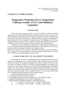
We fabricated prototype force sensors (illustrated by the photographs of the sensor in figure 4), using DuPont 951 LTCC, 6146 conductors, and 2041 (also: ESL 3984) 10 kOhm resistors. Table 1 gives the corresponding data (neutral plane position δ, nominal force F and stress ratio r). We took σd = 50 MPa, integrating a ca. 2x safety margin compared to the long-term strength determined from our measurements. In all cases, b1 = 1 mm and b2 = 3 mm, and the effective length (from load point to resistor) was L = 6 mm. The sensors were designed based on the above calculations, according to the following principles: 1) The sensing resistors are screen printed on the bottom layer only, in a half bridge configuration (only one pair active). 2) The top layer is wide and thin, and the bottom layer narrow and thick, in order to maximise r. 3) The bottom layer is only narrowed at the location of the sensing resistors, maximising rigidity of the beam elsewhere: excessive bending is thus avoided.
Fig. 4. Structured LTCC sensor (b1 = 3 mm, b2 = 1 mm). Left: blank LTCC ; right: screen printed (bottom).
Tab. 1. Calculated properties of our force sensors. h1 [µm] 210 100 40
h2 [µm] 100 40 40
δ [µm] +14 +12 -10
387
F [mN] 290 60 19
r 1.72 1.70 1.67
XXIX International Conference of IMAPS Poland Chapter, Koszalin-Darłówko 19-21.09.2005
The values in table 1 are very promising: we can almost go down to our goal of 10 mN, and the stress ratio (ca. 1.7) almost completely compensates the fact that we only screen print on one side. This means we can achieve ca. the same sensitivity as a full bridge sensor of rectangular cross section with much simpler processing. In spite of this and very promising early measurements, some issues remain, as evidenced in figure 5: the conductive tracks are not well shrinkage matched to the LTCC, leading to deformation of the thin sections upon firing. This must still be resolved if we want to achieve reliable fabrication of very thin beams.
Fig. 5. Side shot of the LTCC cantilevers, showing the deformation induced by the conductive tracks.
4. CONCLUSIONS Our work shows that low-range LTCC force sensing beams can be designed successfully, with superior properties and easier processing than alumina ones. Manufacturing them still poses some challenges, however, due to the deformations of thin structures induced by differential sintering of LTCC and thick-film conductors. Work is underway to address these issues, by more careful layout of the conductive tracks and by modifying the conductor materials in order to match their shrinkage curve to that of LTCC.
REFERENCES [1] B. Morten, M. Prudenziati, "Piezoresistive thick-film sensors", Handbook of Sensors and Actuators vol. 1: Thick Film Sensors, Prudenziati-M (Ed.), Elsevier, Amsterdam 1, 189-208, 1994. [2] T. Maeder-T, C. Jacq, H. Birol, P. Ryser, "High-strength ceramic substrates for thick-film sensor applications", Proceedings, 14th European Microelectronics and Packaging Conference, Friedrichshafen (DE), 133-137, 2003. [3] T. Maeder, D. Genoud, "Solder assembly of cantilever bar force or displacement sensors", Sensor 2001, Nürnberg, Germany, 2001. [4] T. Maeder, P. Ryser, "Effet des interconnexions brasées sur le signal de capteurs de force réalisés en technologie des couches épaisses", 12e Forum de l’Interconnexion et du Packaging Microélectronique, IMAPS Versailles 2002, 37-43, 2002. [5] M. Hrovat, D. Belavic, A. Bencan, J. Bernard, J. Holc, J. Cilensek, W. Smetana, H. Homolka, R. Reicher, L. Golonka, A. Dziedzic, J. Kita, "Thick-film resistors on various substrates as sensing elements for strain-gauge applications", Sensors and Actuators A 107, 261-272, 2003. [6] T. Maeder, H. Birol, C. Jacq, P. Ryser, "Strength of ceramic substrates for piezoresistive thick-film sensor applications", Proceedings, European Microelectronics and Packaging Symposium, Prague, 272-276, 2004. [7] T. Maeder H. Birol, C. Jacq, P. Ryser, "Integrated microfluidic devices based on low-temperature co-fired ceramic (LTCC) technology", Proceedings, 4th Korea-Switzerland Joint Symposium, Materials and MEMS for Life Science Applications, Les Diablerets, 2004. [8] S. Pearson, "Delayed fracture of sintered alumina", Proceedings of the Physical Society of London B69 (12), 1293-1296, 1956. [9] A. Krell, E. Pippel, J. Woltersdorf, W. Burger, "Subcritical crack growth in Al2O3 with submicron grain size", Journal of the European Ceramic Society 23, 81-89, 2003. [10] M. Santo-Zarnik, D. Belavic, "Construction of a PZT actuator in an LTCC structure - a preliminary finite-element analysis", Proceedings, XXVIII International Conference of IMAPS Poland Chapter, 366-370, 2004.
388