Print
Menu
Go Back
Next Page
Design Patterns for Image Processing Algorithm Development on FPGAs K. T. Gribbon, D. G. Bailey and C. T. Johnston Institute of Information Sciences and Technology Massey University, Palmerston North, New Zealand
[email protected] ,
[email protected],
[email protected] Abstract— FPGAs are often used as implementation platforms for real-time image processing applications because their structure allows them to exploit spatial and temporal parallelism. Such parallelization is subject to the processing mode and hardware constraints including limited processing time, limited access to data and limited resources of the system. These constraints often force the designer to reformulate the software algorithm in the process of mapping it to hardware. To aid in the process this paper proposes the application of design patterns which embody experience and through reuse provide tools for solving particular mapping problems. Issues involved in applying design patterns in this manner are outlined and discussed.
I.
INTRODUCTION
Real-time processing is a desirable property of many image processing applications. However, the required performance can be difficult to achieve on conventional serial processors. This is due to several factors such as the large data set represented by an image, and the complex operations which may need to be performed on an image. At real-time video rates of 25 frames per second a single operation performed on every pixel of a 768 by 576 color image (PAL frame) requires 33 million operations per second. This does not take into account the overhead of storing and retrieving pixel values. Many image processing applications require that several operations be performed on each pixel in the image resulting in a large number of operations per second. Field programmable gate arrays (FPGAs) provide an alternative to using serial processors. Continual advances in the size and functionality of FPGAs over recent years has resulted in an increasing interest in their use as implementation platforms for image processing applications, particularly realtime video processing [1]. An FPGA consists of a matrix of logic blocks that are connected by a switching network. Both the logic blocks and the switching network are reprogrammable allowing application specific hardware to be constructed, while at the same time maintaining the ability to change the functionality of the system with ease. As such, an FPGA offers a compromise between the flexibility of general purpose processors and the hardwarebased speed of ASICs. Like ASICs, performance gains are obtained by bypassing the fetch-decode-execute overhead of general-purpose processors and by exploiting the inherent parallelism of digital hardware.
. CATALOG NUMBER
D-ROM Version
A. Exploiting parallelism Parallelism in image processing algorithms exists in two major forms [2]: spatial parallelism, in which the image is divided into multiple sections and processed concurrently, and temporal parallelism, where the algorithm may be represented as a time sequence of simple concurrent operations. FPGA implementations have the potential to be parallel using a mixture of these two forms. For example, in order to exploit both forms of parallelism the FPGA could be configured to partition the image and distribute the resulting sections to multiple pipelines all of which could process data concurrently. Pragmatically, the degree of parallelization is subject to the processing mode and hardware constraints imposed by the system. Based on previous work [3,4] we have identified the following constraints: timing (limited processing time), bandwidth (limited access to data), and resource (limited system resources) constraints. These constraints are inextricably linked and manifest themselves in different ways depending on the processing mode. Managing constraints makes the mapping of image processing algorithms to hardware more challenging as section II demonstrates. B. The mapping process In this paper, mapping is defined as the process of taking a conceptual image processing algorithm and specifying it in some hardware language which can then be subsequently compiled into a netlist. The mapping process can be performed at different levels of abstraction. At the low-level, the designer must manually manage the constraints by hand. To achieve this the design is often specified at the register transfer level (RTL) to help maintain better control of the constraints and allow for flexible optimization. Our previous work [3,4] corroborates this conclusion and shows that it is beneficial to maintain a data flow approach at the register transfer level. Success and significant speed increases over sequential architectures have also been shown in the literature for low-level mappings that use this approach [5-7]. The ‘better control’ described is a function of the low-level programming model used and it follows that the designer must be prepared to deal directly with the hardware constraints and their implications. For example, the timing constraint of realtime processing introduces a number of additional complications. These include such issues as limited memory bandwidth, resource conflicts, and the need for pipelining.
e following catalog numbers must appear on the face of the CD-ROM, on the jacket c wed when the CD-ROM is accessed: IEEE Catalog Number: ISBN:
05CH37710C
0-7803-9312-0
addition, the following CCC Code must be placed on the bottom left hand side of th cording to the guidelines set forth in the attached enclosure: 0-7803-9312-0 /05/$20.00 ©2005 IEEE
Menu
Go Back
Next Page
Design at this level requires specialist knowledge of the underlying hardware. Programming for hardware at the RTL is analogous to programming in assembly language in the software domain. Like assembly language, however, design at the RTL becomes difficult, cumbersome and time consuming for large and complex algorithms. At the other end of the spectrum there are high-level languages and their associated compilers, many of which are based on popular software languages [8-10]. A common goal of these languages is to hide low-level details, such as scheduling and pipelining, from the developer by allowing the compiler to automatically extract parallelism using optimization techniques such as loop unrolling to exploit spatial parallelism and automatic pipelining to exploit temporal parallelism. Thus a working hardware design may be as simple as making a few syntactic modifications to an existing program, compiling it and downloading the resulting configuration file to the FPGA. This allows a more algorithmic approach to hardware design and appears to be a perfect solution for image processing, which already has a large stable code base of well-defined software algorithms for implementing many common image processing operations [11]. This also makes it easy for image processing experts who are used to programming in a software language to make the transition from algorithmic source code to a gate-level representation (netlist) without any knowledge of the underlying low-level issues [12]. The problem with a high-level approach is that the paradigms of hardware and software are fundamentally different. What proves prudent for software programming may prove to be unwise when programming for hardware. For example, a complex expression such as (1),
f ( x) = x2 + x
(1)
can be directly evaluated in software. In hardware however, the multiplication and square root are costly to calculate and direct evaluation may be unwise. High-level languages for hardware give the illusion of programming for software which can reinforce the software ‘mindset’. Ref. [13] has stated that the classical serial architecture is so central to modern computing that the architecture-algorithm duality is firmly skewed towards this type of architecture. If direct mapping of a software algorithm to hardware is performed, compiler optimizations will only improve the speed of what is fundamentally a sequential-based algorithm as the implementation results from [12] demonstrate. Although functionally correct, it may not represent the best algorithm to use for certain processing modes on an FPGA, which could benefit from a completely different and more efficient mapping of the conceptual algorithm to hardware. In these cases the algorithm needs to be rewritten to meet the constraints imposed by the hardware and development reverts to low-level mapping. C. Design patterns: a more flexible solution It is clear that there are shortcomings in the mapping process for both methods described above. Low-level mapping is labor
intensive with little emphasis placed on design reusability. In high-level mapping the ‘software mindset’ often results in less than optimal mappings. Reflection over previous work [3,4,14] has led to the identification of common challenges, in the mapping process under imposed constraints. To address this, we propose applying the concept of design patterns, a common design methodology in software engineering [15] (and originally borrowed from architectural engineering [16]), to the application domain of image processing on FPGAs. Design patterns, as we envisage applying them, identify possible techniques for managing the constraints in different situations and focus on key elements of the solution which may be reusable in subsequent mappings. Recorded patterns provide a way to convey design experience in a structured and informative manner by capturing the essence of the solution. These generalized solutions are not restricted to a specific implementation platform or language and therefore, provide a suitable abstraction that can be applied to emerging languages and hardware in this fast moving area. The use of generalized solutions such as design patterns in the mapping process is not a new concept. Ref. [17] discusses hardware skeletons which are defined as a parameterized description of a task-specific architecture. However, design patterns differ in that they are more abstract. Hardware skeletons can be directly embodied in code, but only examples of patterns can be embodied in code. Other researchers in the field of reconfigurable computing advocate the use of design patterns but take a broader view for general purpose reconfigurable computing [18]. Instead, we opt for a narrower view focused on image processing and the aspects of image processing that make the mapping process difficult. As the constraints play a vital role in the mapping process, section II discusses the constraints, under what circumstances they are imposed and their effect under different processing modes. Section III describes design patterns applied to image processing in more detail and addresses issues of documentation and categorization. In section IV, the application of design patterns to an image processing operation, bilinear interpolation is discussed with respect to the issues illustrated in the paper. Section V closes with a summary of the paper. II.
BACKGROUND
A. Processing modes The constraints outlined above manifest themselves in different ways depending on the processing mode. We believe there are three modes: stream, offline and hybrid processing. In stream processing, data is received from the input device in a raster nature and at video rates. Memory bandwidth constraints dictate that as much processing as possible is performed on the data as it arrives. In offline processing there is no strict timing constraint. This allows time for an entire image to be written to memory and thus random access to memory containing the image data. This mode is the easiest to program, as a direct mapping from a software algorithm can be used. The speed of execution in most cases is limited primarily by the memory access speed.
Menu
Go Back
The hybrid case is a mixture of stream and offline processing. For example, stream processing can be used for image capture and display while offline processing can be used in order to provide random access to a region of interest in the captured image. B. Constraints 1) Timing constraints: The data rate requirements of the application impose a timing constraint which in turn drives the other constraints. If there is no requirement on processing time then the constraint on timing is relaxed and the system can revert to offline processing. The constraint on bandwidth is also eliminated because random access to memory is possible and desired values in memory can be obtained over a number of clock cycles with buffering between cycles. Offline processing in hardware therefore closely resembles the software programming paradigm; the developer need not worry about constraints to any great extent. This is the approach taken by languages that map software algorithms to hardware. The method applies various automatic optimization techniques to produce hardware that processes the input data as fast as possible. Any speedup over an equivalent implementation on a serial processor is deemed useful. This is the underlying approach offered by [8]. In contrast to this, when an image processing application demands real-time processing at video rates, the timing constraints become crucial. For example, video display generation has deadlines on the order of one pixel every 40 ns (VGA output). Stream processing constrains the design into performing all of the required calculations for each pixel at the pixel clock rate. Producing one pixel every 40 ns for non-trivial applications, such as lens distortion correction [3], is difficult because for each pixel complex expressions must be evaluated. These can introduce significant propagation delay, which may easily exceed a single pixel clock cycle. A pipelined approach is thus needed that accepts an input pixel value from the stream and outputs a processed pixel value every clock cycle with several clock cycles of latency, equal to the number of pipeline stages, between the input and output. This allows several pipeline stages each for the evaluation of complex expressions and functions. Pipelining is a relatively easy optimization to perform, since it does not require that the algorithm be modified. In some cases real-time video processing rates are achieved or exceeded when pipelined architecture is created. However, there is no guarantee that compiler optimizations will meet the explicit timing constraints demanded by video rate processing. Some software algorithms do not translate efficiently to hardware because they may access memory in a way which cannot be supported. Subsequently, they do not meet timing constraints regardless of whether pipelining is performed. Chain coding is an example of such an operation [14]. This operation requires random access to memory that cannot be easily achieved in stream processing mode. The algorithm must be rewritten without the requirement of random access to memory using either single or multiple passes through the image [19]. 2) Bandwidth constraints: Under stream processing, some operations require that the image be partly or wholly buffered
Next Page
because the order that the pixels are required for processing does not directly correspond to the raster order in which they are input. This is true for geometric transformations and local filter operations. Consequently developers are forced to deal with resource and bandwidth constraints. Frame buffering requires large amounts of memory. The size of the frame buffer depends upon the transform itself. In the worst case (rotation by 90º, for example) the whole image must be buffered. A single 24-bit (8-bits per color channel) color image with 768 by 576 pixels requires 1.2 MB of memory. Unlike software systems that have large pools of memory and storage available to hold programs and data, FPGAs have comparatively small amounts of memory and storage (logic blocks). The logic blocks themselves can be configured to act like RAM but this is usually an inefficient use of the logic blocks. Typically off-chip memory is used for frame buffering but this may only allow a single access to the frame buffer per clock cycle, which can be a problem for the many operations that require simultaneous access to more than one pixel from the input image (see section IV). Managing bandwidth constraints can involve reformulating the software algorithm [14]. Design patterns can address this issue by aiding in the design of more complex algorithms. 3) Resource constraints: Resource contention arises due to the finite number of available resources in the system such as local and off-chip RAM, or other function blocks implemented on the FPGA. A software system also has finite resources but the sequential flow of execution removes any possible conflict for resource access. The addition of an operating system and its related sub-systems (e.g. memory management sub-system) can also help automate scheduling for resources. On an FPGA, if there are a number of concurrent processes that need access to a particular resource in a given clock cycle then some form of scheduling must be implemented to avoid accessing the same resource at the same time. The worst case involves redesigning the underlying algorithm. Pipelining results in an increase in logic block usage. This is caused by the need to construct pipeline stages and registers rather than being able to reuse the small number of sequential computing elements (ALU and registers), as can be done with offline processing. Flip flops introduced by pipelining typically incur a minimum of additional area on an FPGA, as they are mapped onto unused flip flops within logic blocks that are already used for implementing other combinatorial logic in the design [20]. While the impact of pipeline registers on logic block usage will be minimal, care must still be taken to make efficient use of the available logic blocks. Programming without consideration of the hardware that will be generated has a direct effect on the speed of the implementation. For example, implementations of more complex arithmetic operations such as square roots consume large resources and also increase combinatorial delays if not pipelined. These are especially important consideration for designs using small, low cost FPGAs. Design patterns targeted towards resource constraints can help address some of these issues.
Menu
III.
Go Back
DESIGN PATTERNS
In essence, design patterns are generalized solutions to recurring problems. Borrowing the simplistic example from section I, direct evaluation of complex expressions such as (1) in an FPGA implementation is often an inefficient use of resources and can lengthen combinatorial delays. One solution is to pre-calculate values of the expression and store them in a look-up table (LUT). Therefore, a LUT is a design pattern that can be used to address timing and to a certain extent, resource constraints. This solution is general enough to be applied to any future situations where different complex expressions are encountered, sharing the original vision of design patterns as expressed by [16] who first applied them to architectural design: “Each pattern describes a problem which occurs over and over again in our environment and then describes the core of the solution to that problem, in such a way that you can use this solution a million times over, without ever doing it the same way twice” ([16], pg. x). A. Requirements for documentation Cataloguing design patterns is outside the scope of this paper but a discussion of the simple LUT design pattern will be useful in showing the essential elements [15] that a pattern requires. Firstly, a descriptive pattern name is required to help recognize, communicate, and use the pattern in design at a higher level of abstraction. Secondly, a detailed description of the problem is needed to help recognize when the pattern can be applied. In the LUT pattern example, if the expression to be evaluated contains square root operations, which are costly to implement on an FPGA, then this justifies the use of a LUT. This would require a discussion on what arithmetic operations are expensive or inefficient to perform on an FPGA. The pattern should also contain a description of the elements which make up the solution itself and their relationships. In order to maintain suitable abstraction the solution should not describe a particular implementation, but an example implementation can be presented if applicable. In the LUT pattern example, the solution would describe how to go about creating the entries in the LUT, such as how to calculate and choose a likely range of input values, rather than how to instantiate a LUT in a particular design. Finally, a pattern should also consider the consequences or trade-offs involved in applying the pattern. In the LUT pattern example this may involve discussing the loss of precision that is incurred by replacing the expression with a LUT. We borrow from [15] the standardized form for the description of design patterns. Documenting design patterns helps to convey design experience in a structured way [15]. B. Categorizing design patterns Design patterns can vary greatly in their level of abstraction. For example, pipelining is a design pattern that addresses timing constraints. Pipelining, as mentioned in section II, reduces propagation delays through combinatorial logic by breaking up the logic with registers to store intermediate results. This allows the design to be clocked faster (in order to meet timing constraints) at the expense of increased latency. This pattern is quite abstract in its application because pipelining is almost
Next Page
always used in an FPGA implementation and while the pattern can provide a “rule of thumb” as to when to pipeline it cannot specify what parts of a particular algorithm should be pipelined. On the other hand, the LUT pattern can give more specific guidelines on when a LUT should be applied, such as when an expression contains a square root operation. This leads to an important aspect in our proposal of applying design patterns: taxonomy. As there are many design patterns (discovered, documented and undiscovered) and each can vary in its level of abstraction and purpose, there needs to be a way to categorize them. Categorizing should be performed according to the application domain that design patterns will be applied to. Ref. [16] opted for a hierarchical categorization, viewing the connection between patterns as a linear and dependent sequence of categories from the general (e.g. towns) to the specific (e.g. rooms). This hierarchical categorization suits the architectural domain as rooms only exists in buildings, buildings only exist in neighborhoods, and neighborhoods only exist in towns. Ref. [15] on the other hand have opted for classification according to purpose, which reflects what a pattern does. Thus a pattern can have creational, structural, or behavioral purpose depending on what effect the pattern has on the (programming) object. This suits the object-oriented programming paradigm of the software engineering domain. Thus, we propose categorizing design patterns according to the constraints that they address because in the application domain of image processing we are concerned with how to manage the constraints effectively during the mapping process. One of the goals in design pattern categorization is to investigate the relationships between the various design patterns. These relationships include collaborations, alternatives, and dependencies between patterns. A design pattern can also encapsulate other design patterns as section IV will demonstrate. In this sense design patterns are hierarchical but it is less useful for us to categorize them this way. Design patterns as we envisage applying them, are governed by underlying principles specific to image processing and reconfigurable computing. An understanding of the underlying principles in the application domain is helpful in the discovery and categorization of design patterns. For example, one principle is that the width of memory in off-chip RAM is generally greater than the width of a pixel value. It is therefore possible to pack more than one pixel into a given memory location (e.g. a 32-bit memory location can store two 16-bit RGB pixels or four 8-bit gray-scale pixels if color processing is not required). This pattern can be used to address bandwidth constraints, as more than one pixel can be obtained per access. Where possible design patterns should cover a range of possible solutions so a user can base their choice of patterns in the context of how the problem is presented and the imposed constraints. In order to show how knowledge of design patterns can simplify the design process and encourage reusability, an example will be undertaken.
Menu
IV.
Go Back
Next Page
EXAMPLE
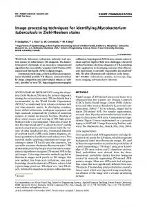
Spatial transformations, such as digital zooming or rotation redefine the “arrangement” of pixels on the image plane. The coordinates for new pixels in the transformed image are rarely integer values and are generally located in “between” pixels in the original image. To calculate the values of these new pixels bilinear interpolation is often used as it provides a satisfactory compromise between computational efficiency and image quality [21]. The algorithm obtains the pixel value by taking a weighted sum of the pixel values of the four nearest neighbors surrounding the calculated location as shown below in Fig. 1 and (2):
Figure 1. Bilinear interpolation neighborhood
I ( p ) = (1 x f )(1 y f ) I (1 x f ) y f I
xi yi
xi yi + 1
xi + 1 yi xi + 1 yi + 1
+ (1 y f ) x f I + xf yf I
(2)
Obtaining the pixel values of the neighborhood in Fig. 1 is trivial to perform in offline processing or in software as values can be retrieved over a number of clock cycles. However, the constraints imposed by a real-time implementation can complicate the design. As section II discussed, video rate processing for the display requires that one pixel be produced every 40 ns and for each pixel (2) must be evaluated. This can introduce significant propagation delay. Simultaneous access to four pixels in the input image is also required every clock cycle according to (2). This introduces a bandwidth constraint as potentially only a single access can be made to the frame buffer per clock cycle. In addition to these “hardware” based constraints, the problem itself introduces additional constraints as the presentation of the input data is dependent on the spatial transform itself. For example, in simple zooming operations the calculated coordinates will be presented in a raster-based fashion. Pure rotation operations introduce additional complications because the coordinates now appear on straight lines at the angle of rotation, one pixel apart. To address all of these problems design patterns that can be applied.
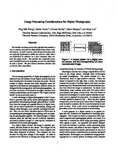
As detailed in section II, spatial transforms require frame buffering. To achieve this we can apply a design pattern for frame buffering. The applied pattern will depend on the memory architecture of the system. Possible patterns to deal with frame buffering are the use multi-port RAM, multiple RAM banks in parallel or using a faster RAM clock to read multiple locations in a single pixel clock cycle. While each of these frame buffering patterns also aids in the alleviation of the memory bandwidth constraint by allowing multiple accesses, the consequences of using any of these patterns must also be weighed. Multi-port RAM is specialized and expensive. The use of multiple banks is clumsy because the added redundancy is expensive in both cost and space. Finally, using a faster RAM clock requires high speed memory and introduces synchronization issues. In many cases we apply the design pattern of double frame buffering as our hardware system only provides single-port access to off-chip memory. Effectively this pattern uses two frame buffers allowing the stream from the camera to be written to one bank while a stream from the other bank is read and processed. When the stream from the camera reaches the end of a frame the roles of the banks are swapped. To overcome timing constraints the pipelining design pattern can be applied. This allows several pipeline stages for the calculation of (2). Problem knowledge, however, can somewhat alleviate the requirements on the bandwidth constraint. Bilinear interpolation in (2) is effectively a 2×2 window filter with weights that vary according to the location within the image. As the window is shifted by a single pixel each time half of the neighborhood values can be obtained from the previous calculation. A third pixel value can be obtained from the frame buffer, leaving the last pixel value unknown. Depending on the application requirements and hardware specifications, the pack memory pattern detailed in the previous section can be used to help obtain the final pixel value. One of the tradeoffs is that in general it requires the use of lower color depth, such as 16-bit RGB as opposed to 24-bit RGB, or grayscale processing, which may be prohibitive for some applications. The pattern can enable more than one pixel to be retrieved in a single access. Alternatively, recognition that bilinear interpolation is effectively a 2×2 window filter, as mentioned above, allows the application of a row buffering design pattern as shown below in Fig 2:
Figure 2. Bilinear interpolation using row buffering design pattern which can also be applied to window filtering
Menu
Go Back
In Fig 2. input data from the previous row is buffered using a shift register (or circular memory buffer) for when the window is scanned along subsequent lines. Pixel values for interpolation can now be obtained from the previous calculation, the frame buffer and a single row buffer. This design pattern can also be reapplied to any window filtering operation. “Harder” spatial transforms typical of applications such as lens distortion correction make the on-demand row buffering design pattern in Fig 2. ineffective because the coordinate path may be curved and the coordinate step size may not be uniform. To overcome this we can use a design pattern that utilizes the principle that (in display generation) there are more clock cycles on a row and frame than there are pixels, due to the horizontal and vertical blanking periods. This gives rise to the preloading buffer design pattern. During the blanking period of the display, where processing is stalled, a separate process can be used to preload a buffer with pixel values for the next row from the frame buffer. The pixel values could be preloaded in some “dumb” fashion (i.e. row-by-row) or according to certain conditions, such as only values that are likely to be used in subsequent calculations, in order to maximize buffer efficiency. This example demonstrates that trivial software algorithms like bilinear interpolation are quickly complicated by real-time processing constraints. A hardware implementation reveals many considerations such as problem constraints, processing modes and available hardware, leading to a range of design patterns. Choosing a design pattern that meets all these considerations for the particular problem at hand is the key to an efficient hardware implementation. V.
REFERENCES [1] [2] [3]
[4]
[5]
[6] [7]
[8]
[9]
[10]
SUMMARY
FPGAs are often used as implementation platforms for realtime image processing applications because their structure can exploit spatial and temporal parallelism. High-level languages and compilers which automatically extract parallelism from the code do not always produce an efficient mapping to hardware. The code is usually adapted from a software implementation and thus has the disadvantage that the resulting implementation is based fundamentally on a serial algorithm. Low-level mapping can overcome the ‘software mindset’ but as a consequence the designer must now deal more closely with the constraints, which is labor intensive and places little emphasis on reusability. Design patterns offer an answer to this by directly addressing the common challenges and imposed constraints of the mapping process and focusing on key elements of the solution which may be reusable in subsequent mappings. Recorded patterns also help convey design experience in a structured manner. ACKNOWLEDGMENT The authors would like to acknowledge the Celoxica University Programme for generously providing the DK3 Design Suite.
[11] [12] [13] [14]
[15] [16] [17] [18]
[19] [20] [21]
Hutchings, B. and Villasenor, J., “The Flexibility of Configurable Computing,” IEEE Signal Processing Magazine, vol. 15, pp. 67-84, September 1998. Downton, A. and Crookes, D., “Parallel Architectures for Image Processing,” IEE Electronics & Communication Engineering Journal, vol. 10, pp. 139-151, June 1998. Gribbon, K. T., Johnston, C. T., and Bailey, D. G., “A Real-time FPGA Implementation of a Lens Distortion Correction Algorithm with Bilinear Interpolation,” Proceedings of the Image and Vision Computing New Zealand Conference 2003, Massey University, Palmerston North, New Zealand, pp. 408-413, November 2003. Gribbon, K. T. and Bailey, D. G., "A Novel Approach to Real-time Bilinear Interpolation," Second IEEE International Workshop on Electronic Design, Test and Applications, Perth, Australia, pp. 126-131, January 2004. Alves de Barro, M. and Akil, M., "Low Level Image Processing Operators on FPGA: Implementation Examples and Performance Evaluation," Proceedings of the 12th IAPR International Conference on Pattern Recognition , Jerusalem, Israel, pp. 262-267, October 1994. Woods, R., Trainor, D., and Heron, J.-P., “Applying an XC6200 to realtime image processing,” IEEE Design & Test of Computers, vol. 15, no. 1, pp. 30-38, 1998. Benkrid, K., Crookes, D., and Benkrid, A., “Design and implementation of a novel algorithm for general purpose median filtering on FPGAs,” IEEE International Symposium on Circuits and Systems, pp. 425-428, 2002. Najjar, W. A., Böhm, W., Draper, B. A., Hammes, J., Rinker, R., Beveridge, J. R., Chawathe, M., and Ross, C., “High-level language abstraction for reconfigurable computing,” IEEE Computer, vol. 36, pp. 63-69, August 2003. Haldar, M., Nayak, A., Choudhary, A., and Banerjee, P., “A system for synthesizing optimized FPGA hardware from MATLAB ,” Proceedings of the 2001 IEEE/ACM international conference on Computer-aided design, San Jose, California, pp. 314-319, 2001. Crookes, D. , Benkrid, K., Bouridane, A., Alotaibi, K., and Benkrid, A., “Design and Implementation of a High Level Programming Environment for FPGA-Based Image Processing,” IEE Proceedings-Vision Image and Signal Processing, vol. 147, pp. 377-384, August 2000. Webb, J. A. , “Steps toward architecture-independent image processing,” IEEE Computer, vol. 25, no. 2, pp. 21-31, 1992. Alston, I. and Madahar, B., “From C to netlists: hardware engineering for software engineers?” IEE Electronics & Communication Engineering Journal, vol. pp. 165-173, August 2002. Offen, R. J. VLSI Image Processing, London: Collins, 1985. Johnston, C. T., Gribbon, K. T., and Bailey, D. G., “Implementing Image Processing Algorithms on FPGAs,” Proceedings of the Eleventh Electronics New Zealand Conference, Palmerston North, New Zealand, pp. 118-123, November 2004. Gamma, E., Helm, R., Johnson, R., and Vlissides, J. Design Patterns: Elements of Reusable Object-Oriented Software, United States of America: Addison-Wesley Publishing Company, 1995. Alexander, C., Ishikawa, S., Silverstein, M., Jacobsen, M., FiksdahlKing, I., and Angel, S. A Pattern Language, New York: Oxford University Press, 1977. Benkrid, K. , Crookes, D., and Benkrid, A., “Towards a general framework for FPGA based image processing using hardware skeletons,” Parallel Computing, vol. 28, pp. 1141-1154, August 2002. DeHon, A., Adams, J., DeLorimier, M., Kapre, N., Matsuda, Y., Naeimi, H., Vanier, M., and Wrighton, M., “Design patterns for reconfigurable computing,” 12th Annual IEEE Symposium on Field-Programmable Custom Computing Machines, pp. 13-23, 2004. Zingaretti, P., Gasparroni, M., and Vecci, L., “Fast chain coding of region boundaries,” IEEE Transactions on Pattern Analysis and Machine Intelligence, vol. 20, no. 4, pp. 407-415, 1998. Xilinx, Inc. Xilinx ISE 7 Software Manuals and Help. 2005. Gonzalez, R. C. and Woods, R. E. Digital Image Processing, Upper Saddle River, New Jersey: Prentice-Hall, 2002.