International Conference on Renewable Energy Research and Applications
Madrid, Spain, 20-23 October 2013
Design and Simulation of a SCADA System using SysML and Simulink Dogan GEZER1,2, Hakki Ozgur UNVER1, Yigit TASCIOGLU1, Kutay CELEBIOGLU1, Selin ARADAG1 1
TOBB University of Economics and Technology Dept. of Mechanical Engineering Ankara, Turkey
[email protected],
[email protected] [email protected],
[email protected] [email protected]
Abstract—This paper describes a methodology and a case study through which system architecture and dynamic models of related system components are gathered in order to design and simulate the SCADA system of a new hydro turbine test laboratory. System architecture model is prepared in System Modeling Language, a system modeling language based on Unified Modeling Language, while the dynamic model of the laboratory is formed in Matlab/Simulink. Some simulations are performed in order to verify the preliminary system design studies and system requirements. Keywords-System Modeling Language (SysML); SCADA system;
I.
INTRODUCTION
System engineering is an engineering approach that focuses on design and management of interdisciplinary and generally complex projects. System engineering is a top-down process considering the success of the system by concentrating the whole [1]. As the project gets larger, it becomes more difficult to deal with coordination and traceability of the project. Therefore, a need of a flexible and standard tool for system engineering has emerged. In 2001, Model Driven System Design workgroup of International Council on Systems Engineering (INCOSE) decided to adapt Unified Modeling Language (UML), a modeling language for software engineering which involves graphical notational techniques to model object-oriented software application visually, for the field of system engineering [2]. System engineers who used UML for general-purpose visual modeling had to model additional concepts in other modeling tools which made integration and traceability of these models difficult. In 2003, Object Management Group (OMG) requested proposals for customization of UML in order to support modeling of various systems including hardware, software, data, personnel, procedures and facilities. Only one proposal based on UML 2.0 was submitted to that request. Main aim of this submission was to use UML 2.0 as much as possible and not to make any changes unless absolutely necessary [3]. Those efforts resulted in System Modeling Language (SysML) which is a general
2
TUBITAK Marmara Research Center Energy Institute Ankara, Turkey
[email protected]
purpose graphical modeling language for specifying, analyzing, designing and verifying complex projects including hardware, software, information, communication and interface components [4]. Dynamic modeling of a system is a very critical link between system design and implementation where computational approaches and mathematical representations are used. Dynamic system models include internal dynamics and memory of past states as distinct from static system models which focus on time-invariant system features. A new technology center, named TOBB ETU Hydroturbine Design and Test Center, is built in Ankara, Turkey to develop hydropower technology on national level, as the most plentiful and used renewable energy resource in Turkey. This laboratory is planned to have a 2 MW testing capacity for hydro turbines which is 25 % greater than the known highest testing capacity in the world. Design studies for the SCADA system of the laboratory continues in coordination with the design of the electromechanical components of the test set-up. The SCADA system is responsible of real-time control, data acquisition and the other requirements mentioned in following sections. In order to validate the complex system behavior of the SCADA system which is defined in the SysML model, it is necessary to test, verify and simulate the SysML model with the help of the dynamic model generated in Matlab/Simulink. Simulations performed in dynamic model give an idea on whether the system preliminary design satisfies the requirements or not. The similarities and the differences between SysML and UML are explored expressing that SysML only provides a set of useful systems engineering extensions to the UML and SysML is simply not a new language [5]. Considering the system design in SysML, in [6], the design of a packaging machine on a SysML-based methodology is mentioned. An extension to SysML that enables continuous-time behavior description and thus enables co-simulation with Matlab/Simulink is proposed in [7]. In [8], control system of a transmission system is designed with SysML and Simulink.
978-1-4799-1464-7/13/$31.00 ©2013 IEEE ICRERA 2013
1058
International Conference on Renewable Energy Research and Applications
Madrid, Spain, 20-23 October 2013
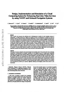
Figure 1. Diagram taxonomy of SysML Figure 2. Requirement Diagram
The rest of the paper is organized as follows: In Section II the development of the system architecture model using SysML is explained. The details of the dynamic model in Simulink are presented in Section III. Simulation scenarios and the results are provided in Section IV. Section V concludes the paper. II.
SYSTEM ARCHITECTURE MODELING USING SYSML
The main aim of SysML is to provide simple however effective constructs for modeling a wide range of system engineering problems. In particular, SysML is very powerful for specifying requirements, structure, behavior, allocations and parameters while supporting multiple processes and methods [9]. SysML defines nine types of diagrams included in groups as Behavior, Requirement and Structure diagram. Diagram taxonomy of SysML is shown in Figure 1. As noticed, some of the diagrams are inherited from UML, some are extensions of UML and two of them are new diagram types. The SCADA system of the laboratory is divided into two levels as station level and local control level. Project servers, data loggers and workstations are at the station level and
operators give setpoints and sequence start and stop commands through operator screens. The local control level is composed of the controllers, input/output (I/O) modules, communication and function modules and the energy analyzers. Data exchange between site equipment and I/O modules is achieved through hardwired signals. AC Motors and pumps are controlled in order to provide desired water pressure and flow conditions. AC Motors are fed through AC bus which is connected to the electric grid. The SCADA system controls the amount of water passing through the turbine under adjusted water pressure conditions. The turbine being tested and the DC machine are coupled and the speed of the DC machine is determined by the turbine. DC power generated by the DC machine is converted into AC power by an inverter. A. Requirement Diagram A requirement defines a capability or a condition to be satisfied. In a SysML model, it is possible to express text-based requirements on graphics, tables or with the help of a tree structure. In a requirement diagram, requirements and their relationships with other system elements are defined. Requirements satisfied by the SCADA system and its subcomponents are shown for each requirement block in Figure 2.
Figure 3. Block Definition Diagram of the Laboratory
ICRERA 2013
1059
International Conference on Renewable Energy Research and Applications
Madrid, Spain, 20-23 October 2013
Figure 4. Internal Block Diagram of the SCADA System
B. Block Definition Diagram Block definition diagram is used for defining features of the block which are modular units of system description and relationships between them including associations, generalizations and dependencies. The block diagram of the laboratory is shown in Figure 3, including the system elements and quantities of each element in the system.
E. Use cases The usage of a component modeled in SysML model by an environmental effect is visualized by use case diagrams on which selected actors realize a desired goal. Use case diagrams include actors, use case and relationships such as communication, include, extend and generalization. Figure 5 shows the use cases for the SCADA system.
C. Internal Block Diagram In SysML, internal block diagram shows the internal structure of a block in details with properties and connections between those properties. In Figure 4, internal block diagram of the SCADA system are seen. I/O modules, energy analyzer, project server, workstation and time synchronization server are all included in the SCADA system and their data exchange media with the main controller are backplane, Profibus (DP) and Ethernet.
F. Activity Diagram Activity diagrams are used for expressing inputs, outputs, sequences and conditions in order to coordinate other behaviors and activities in terms of sequence of actions.
D. Parametric Diagram In parametric diagrams, block properties are constrained through constraint blocks. A constraint block defines an objective function by which alternative solutions are compared.
Figure 5. Use Case Diagram for Operation and Maintenance
ICRERA 2013
G. State Diagram State diagram is used for modeling discrete behavior in terms of transitions and states. The SCADA system defines the state of the laboratory as standstill, no-load operation and load operation as could be seen in Figure 6. H. Package Diagram Package diagram is composed of packageable elements and it establishes the relations between these elements.
Figure 6. State Diagram of the Laboratory
1060
International Conference on Renewable Energy Research and Applications
Madrid, Spain, 20-23 October 2013
Figure 7. Sequence Diagram of SCADA System
I.
Sequence Diagram Sequence diagram is a good way of showing interactions through flow of control between actors and components. Messages or data exchanged through the focused scenario are displayed in a chronological order. The sequence diagram for unit start-up is shown in Figure 7. III.
DYNAMIC SYSTEM MODELING USING SIMULINK
The dynamic system model of the laboratory is generated in Matlab/Simulink. Dynamic model is composed of models of laboratory equipment and interactions between them as shown in Figure 8 generically.
Setpoints are given at the station level. PID controller in local control level sends position set point to servo drive and thus controls wicket gates in order to adjust water flow into the turbine. At the same time, the local controller keeps the oil pressure in the system at a predefined level by controlling the motor and the pumps of high pressure oil system. AC motors and the pumps are fed from the AC grid and controlled by the SCADA system in order to provide constant hydraulic pressure to test the turbine [10]. DC machine and external excitation of the DC machine is used for generating DC power and regulating voltage output of the machine terminals. Through the inverter, DC voltage is changed into AC voltage which has magnitude and frequency of the grid. IV.
SIMULATION
The startup of the turbine by controlling the high pressure oil system and wicket gates in the dynamic model generated in Simulink is shown in Figure 9. Startup of Turbine 1 0.9 0.8
Turbine Speed (pu)
0.7 0.6 0.5 0.4 0.3 0.2 0.1 0
Figure 8. Generic Components of Dynamic Model
ICRERA 2013
0
5
10
15 Time (seconds)
20
25
30
Figure 9. Startup of the Turbine
1061
International Conference on Renewable Energy Research and Applications
Madrid, Spain, 20-23 October 2013
Change in Valve Opening
Change in Motor Speed
1
1.05
0.6
Speed (pu)
Valve Opening (pu)
0.8
0.4
1
0.2
0
0
5
10
15 20 25 Time (seconds)
30
35
0.95
40
0
5
10
Change in Pump Pressure
15 20 25 Time (seconds)
30
35
40
30
35
40
Change in Mechanical Power
1.01 1
Mechanical Power (pu)
Pressure (pu)
1.005
1
0.995
0.8
0.6
0.4
0.2
0.99
0
5
10
15 20 25 Time (seconds)
30
35
0
40
0
5
10
15 20 25 Time (seconds)
Figure 10. Changes in motor-pump system: a) Change in Valve Opening, b) Change in Pump Pressure, c) Change in Motor Speed, d) Change in Mech. Power
In order to investigate the functionality of the motor and pump set in the hydraulic system, valve openings are changed and the variations in pump pressure, speed and mechanical power of the motor which is coupled to the pump are shown in Figure 10. V.
CONCLUSION
In this paper, preliminary design studies of a hydro turbine design and test laboratory through generation of system architecture model in SysML and system dynamic model generated in Matlab/Simulink are explained. Considering the results of the simulations in Simulink, system requirements and electromechanical equipment’s specifications are verified as well as successful operation of the laboratory equipment individually and as a whole are validated. ACKNOWLEDGMENTS The design and the construction of the Hydroturbine test facility is financially supported by Turkish Ministry of Development and TOBB.
ICRERA 2013
REFERENCES [1]
MIT OpenCourseWare, [Online]. Available: http://ocw.mit.edu/cour ses/engineering-systems-division/index.htm [2] SysML Open Source Specification Project, [Online]. Available: http://www.sysml.org/ [3] Hause, M.; et al., "Inside SysML," Computing & Control Engineering Journal , vol.16, no.4, pp.10,15, Aug.-Sept. 2005 [4] OMG System Modeling Language, [Online]. Available: http://www.omgsysml.org/ [5] Holt, J.; Perry, S., "SysML: describing the system [Notebook: modelling languages]," Information Professional , vol.3, no.4, pp.35,37, August-September 2006 [6] Bassi, L.; et al., "A SysML-Based Methodology for Manufacturing Machinery Modeling and Design," Mechatronics, IEEE/ASME Transactions on , vol.16, no.6, pp.1049,1062, Dec. 2011 [7] Kawahara, R.; et al., "Verification of embedded system's specification using collaborative simulation of SysML and simulink models," Model-Based Systems Engineering, 2009. MBSE '09. International Conference on , vol., no., pp.21,28, 2-5 March 2009 [8] Sakairi, T.; et al., "Designing a control system using SysML and Simulink," SICE Annual Conference (SICE), 2012 Proceedings of , vol., no., pp.2011,2017, 20-23 Aug. 2012 [9] OMG Systems Modeling Language (OMG SysML™), V1.0 Specs, [Online]. Available: http://www.omg.org/spec/Sys ML/1.3/ [10] Demonstration of a hydraulic pump driven by an electric motor using SimPowerSystem and SimHydraulics, [Online]. Available: http://www.mathworks.com/matlabcentral/fileexchange/33313
1062