Al-Nahrain Journal for Engineering Sciences (NJES)
Vol.20 No.3, 2017 pp.600-614
Design of SCADA System for Oil Pipeline Control Using LabVIEW Laith Abed Sabri
Subhi Aswad Mohammed
Mohammed Ibrahim Issa
Dep. of Mechatronics Eng. University of Baghdad
[email protected]
Dep. of System Engineering University of AL-Nahrain
[email protected]
Oil Pipeline Company (OPC) Ministry of Oil
[email protected]
is that the user can easily monitor the status of the overall system. Z. Aydogmus [2] has implemented SCADA system control via Programmable Logic Controller (PLC) for a fluid level control system with fuzzy controller to achieve the parameters of the membership functions, Matlab/Simulink program has been used. A. M. Ali [3] has presented study for scarce water resources. The research design SCADA system for managing the water pumping stations for 40 wells. K. Parwal [4] presents an implementation of fuzzy technique based on LabVIEW for control gas system, and develop a special testing machine for testing the weak points at the pipe connections e.g. pipe bends, and intermediate connections. The remainder of this paper is organized as follows: in section 2, a brief overview of SCADA system architecture. In section 3, present oil plant process control system architecture. Section 4 specifies oil pipeline network. In section 5, discuss batch scheduling operation, their problems of sharing pipeline and their transmix problem description. Mathematical and state space model of system are presented in section 6. Section7 describe process operations mangement and design HMI for SCADA, and the result of scada system simulation shown in section 8 . In section 9 conclusions are shown and future work is suggested.
Abstract The paper describes a design and simulation of a Supervisory Control And Data Acquisition (SCADA) system to control oil pipeline and depot plant. The aim of the process is to control oil transportation through a shared pipeline and to minimize products contamination. The study attempts to fulfill an optimal sequence of batches of refined products to satisfy the customer demands in term of: volume , maximum flow rate, optimizing the total operational cost, and reducing products contamination. The proposed system introduces a control algorithm to perform process control system functions and for achieving the tasks and actions in specific sequences and precedence. The control algorithm performs processing of pumping station control, sharing single oil pipeline, maintaining tanks level, and depot inventory control. This paper investigate many factors which effects the length of transmix segment, which enable to offer optimum solutions to reduce products contamination. LabVIEW software is used for performing various signals acquisition and monitoring, also for simulating and designing the control system strategy.
Keywords: SCADA System, Oil Pipeline, Labview, Slob/Transmix, Oil Depot.
1. Introduction
2. SCADA System Architecture
Scheduling the products as batches in pipelines is a complex task having many constraints. Both producer’s production schedules and market demands with the operational constraints are forbidding some products to be pumped one after another, all of these are to be considered. Actual inventories available in the storage tanks at the source and the distribution terminals as well as the product batches are already in transit to the nominated destination. SCADA systems are types of industrial control system used to collect data and to perform controlling process from a remote location. They can control water transportation systems, refineries, chemical plants, and a wide variety of manufacturing operations in the industry [1]. One advantage of a SCADA system
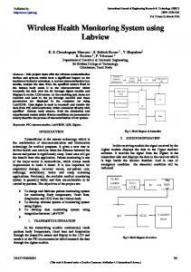
The SCADA system consists of the following main components as shown in Figure (1). [5]
Figure (1): SCADA System Architecture
600
NJES Vol.20, No.3, 2017
Sabri et al., pp.600-614 The pipeline system is divided into different segments (pipes) that connect the nodes of the distribution network. Each pipe is modeled as a fixed-size FIFO queue with a single server at the pipe extreme that permits the movement of material entities from one position to another by combining different pipes, with particular sizes and service rates [6]. When an entity enters a pipeline segment at the inlet point, it pushes the entity positioned at the other extreme out of the queue. In other words, at every pipe end, a reservoir is located that dispatches the first entity on the queue whenever a new entity enters the pipe at the inlet section. Since the system transports multiple products, the model keeps track of every pipeline fill by updating the reservoir queues at every time event.
a. Remote Terminal Unit ( RTU ) The RTU gathers status data from field devices, monitoring, controlling of the remote location and transmit data and control signals to a central monitoring and control station (MTU).
b. Communications and Network System In order for the central MTU to communicate with the RTUs that are located at the distant locations a communication link must exist to transfer data from one location to another.
c. Human Machine Interface (HMI) The SCADA operates using HMI to presents data to the operator, configure, monitor the system state and generate different control activities.
d. SCADA Software There are several software packages used for designing HMI and SCADA. WINCC, CIMPLICITY HMI, and LOOKOUT are examples for commercial SCADA packages.
4.Oil Pipeline Operation Batch Scheduling
e. Master Terminal Unit (MTU)
The problem of interest in this research is concerned with the sequencing of batches of different refined products to be shipped via single pipeline system in order to minimize the total operational costs in a given period of time. Also satisfying the considered operational constraints of the system and the demand satisfaction of the different products at the different market zones within the corresponding delivery time. The challenge is to achieve an optimal sequence of batches of refined products to satisfy the customer demands while optimizing the total operational cost of the system or another operational objective of interest. [6]
The MTU is the centralized controller for the SCADA system. MTU initiates all communication, gathers data, stores information, and interfaces with operators. MTU processes the information received, sends it to the RTU sites, and presents it to human operators in a form that the operators can work with it.
3. Oil Plant Process Control System Process control system for distribution of oil product, which consists of the following components:
• Oil Field • Refinery Plant • Pumping Station • Oil Depot Plant • Pipeline Network • Oil Product Distribution Terminal
a.
Problems of Sharing Oil Pipeline
Products transfer must satisfy the volume and maximum flow rate that are the constraints in the pipeline. There are also forbidden of specific batch sequences of products in the pipeline. The Operation of multiproduct pipelines has a unique feature, product contamination. Although pipelines provide a safe mode of transportation, product contamination is inevitable and it occurs at the interface of two miscible products. As products are transported by only one pipeline and very large distances must be covered, it is critical mission that the correct decisions should be made.
The oil plant started from filed to distribution terminal output as shown in Figure (2).
b. Transmix Problem Description The main problem in the single pipeline system is sharing pipeline resource for transporting oil product from the source to the storage plant (oil depot). The sequential pumping of products will leads to a mixing of different oil products called (transmix) as shown in Figure (3) .[7]
Figure (2): Oil Plant and Pipeline System
601
NJES Vol.20, No.3, 2017
Sabri et al., pp.600-614 in the flow. It has point velocity vectors in all directions Pipe flow will be laminar for a Reynolds Number (Re) less than 2100 and it will be turbulent for a (Re) greater than 4000. For (2100 < (Re) < 4000), called the transition region, the flow may be either laminar or turbulent, depending upon factors like the entrance conditions into the pipe and the roughness of the pipe surface [8].
Figure (3): Transportation in Single Pipeline The study of transmix characteristics allows defining the quality of product based on the contamination value when different products are dispatch through a single line continuous succession. There is always a mixing at the boundary of two adjacent streams and a slug of contaminates is formed between batches of different uncontaminated products. This slug of contaminated material gradually increases in length as two streams flow along the line in the direction of the receiving points A, B: Pure Products; C: interface length as shown in Figure (3), the contamination length is the distance between two points in the interface where sampling indicates a change in composition from 99% of one product to 99% purity of the other. There are many effective factors which effects on the length of transmix segment: i. The distance transfer by the interface (Transmix). ii. The mean velocity of the flow in the pipeline. iii. The internal diameter of pipeline and the curvature of the pipe. iv. The Reynolds s number. v. The kinematic viscosity of the product mixture. vi. The pipe friction coefficient and the relative roughness in the pipe.
Figure (4): Types of Flow
The Reynolds Number for flow in pipes is defined as: 𝑅𝑅𝑒𝑒 =
Where:
𝐷𝐷𝐷𝐷𝐷𝐷 𝜇𝜇
(1.1)
• D is the diameter of the pipe in (m) • V is the average fluid velocity in (m/s) The definition of average velocity is: V = Q/A Where: • Q is the volumetric flow rate • A is the cross-sectional area of flow 3
• ρ is the density of the fluid in (kg/m )
5.1 The Bernoulli Equation The Bernoulli equation is an approximate relation between pressure, velocity, and elevation, and is valid in regions of steady, incompressible flow where net frictional forces are negligible. it has proven to be a very powerful tool in fluid mechanics[8].
5. Mathematical Model Of Oil Pipeline System There are three type of flow in the pipe:
i. Laminar Flow All of the fluid velocity vectors line up in the direction of flow.
ii. Transition Flow The flow fluctuates between laminar and turbulent flows before it becomes fully turbulent.
iii.
2
• μ is the viscosity of the fluid in (N.s/m )
Turbulent Flow
Takes place in flow situations with high fluid velocity and low fluid viscosity. The Figure (4) illustrate differences between laminar and turbulent flow in a pipe. Turbulent flow is characterized by turbulence and mixing
Figure (5): Bernoulli Equation
602
NJES Vol.20, No.3, 2017 𝑃𝑃 𝑉𝑉 2 + + 𝑔𝑔𝑔𝑔 = 𝑐𝑐𝑐𝑐𝑐𝑐𝑐𝑐𝑐𝑐𝑐𝑐𝑐𝑐𝑐𝑐 2 𝜌𝜌
Sabri et al., pp.600-614
(1.2)
This is the famous Bernoulli equation (Figure (5)), which is commonly used in fluid mechanics for flow along a streamline in in viscid regions of flow. The Bernoulli equation can also be written between any two points on the same streamline as: 𝑃𝑃2 𝑉𝑉 2 𝑃𝑃1 𝑉𝑉 2 + + 𝑔𝑔𝑔𝑔1 = + + 𝑔𝑔𝑔𝑔2 (1.3) 2 2 𝜌𝜌 𝜌𝜌
Where: • • •
𝑽𝑽𝟐𝟐 𝟐𝟐
gz
𝑷𝑷 𝝆𝝆
as kinematic energy as potential energy as flow energy
All per unit mass. Therefore, the Bernoulli equation can be viewed as an expression of mechanical energy balance and can be stated as follows: The sum of the kinetic, potential, and flow energies of a fluid particle is constant along a streamline during steady flow when compressibility and frictional effects are negligible.
Figure (6): Schematic Diagram of The System 𝑞𝑞𝑖𝑖 = 𝑘𝑘𝑖𝑖 𝑣𝑣𝑖𝑖 𝑦𝑦𝑖𝑖 = 𝑘𝑘𝑠𝑠 ℎ𝑖𝑖
(1.5) (1.6)
Where; • V is the applied voltage to the pump motor i
• Q is the input flow rate; i
• h is the liquid level;
5.2 Physical Model of Pipeline System
1
• y is the output voltage
Mathematical models are developed that describe the relationship between different quantities of process system. It concerns with quantitative rather than a qualitative treatment of the process. Typical oil industry consists of various processes and measurements, operated with different parameters in order to implement specific tasks. If we consider mass balance equation it is used to describe the relation between the mass input and mass output for just one of the tanks as shown in eq.1.4. [8] (Mass flow in - Mass flow out) = (Rate of change of liquid level volume) 𝑑𝑑ℎ (1.4) 𝐴𝐴 = −𝑄𝑄𝑜𝑜𝑜𝑜𝑜𝑜 + 𝑄𝑄𝑖𝑖𝑖𝑖 𝑑𝑑𝑑𝑑
1
• K is the pump characteristic; i
• K is the sensor characteristic s
5.3 Modeling of Storage Tank System Initially consider the single tanks with valve A closed and valve B open. This system is a single tank process that can be drawn as shown in Figure (7).
Where:
• •
2
A is the cross sectional area of tank (m ) V is the volume of liquid in tank (m/s)
(V = A.H) 3
•
Q
•
Q
in
is the pump flow rate for inlet (m /s)
out
3
is the flow rate outlet (m /s)
Figure (7): Tank System
The overall system represent schematically in Figure (6).
The system model is described eq. 1.7, and determined by relating the flow into the tank to that leaving via valve B. Hence, [8] (Rate of mass accumulation) = ( Rate of mass in - Rate of mass out) (Q – Q) = Rate of change of liquid volume i
603
b
NJES Vol.20, No.3, 2017 𝑄𝑄𝑖𝑖 − 𝑄𝑄𝑏𝑏 =
𝑑𝑑𝑑𝑑 𝑑𝑑𝑑𝑑
= 𝐴𝐴
𝑑𝑑ℎ 𝑑𝑑𝑑𝑑
Sabri et al., pp.600-614
(1.7)
−
If valve B is assumed to behave like a standard sharp edged orifice, then the flow through valve B will be related to the fluid level in the tank, H , by
Where the parameters used above are;
1
𝐴𝐴 𝑇𝑇𝑇𝑇𝑇𝑇𝑇𝑇 is the cross-sectional area of tank 𝑎𝑎𝑜𝑜𝑜𝑜𝑜𝑜 is the cross-sectional area of outlet hole
applying Bernoulli equation eq. 1.7, 𝑃𝑃1 𝑉𝑉 2 + + 𝑍𝑍1 + ℎ𝑝𝑝𝑝𝑝𝑝𝑝𝑝𝑝 2 𝜌𝜌 𝑃𝑃2 𝑉𝑉 2 = + + 𝑍𝑍2 2 𝜌𝜌 + ℎ𝐿𝐿 (1.8)
hi is the Product level in tank i g is the acceleration due to gravity 9.81 m/s2
5.4 State Space Models A general compact form of the state-space model is [9]. (1.13) 𝑥𝑥̇ = 𝐴𝐴𝐴𝐴 + 𝐵𝐵𝐵𝐵 𝑦𝑦 = 𝐶𝐶𝐶𝐶 + 𝐷𝐷𝐷𝐷 (1.14) Where x is the state vector and u is the input vector to the system. A is referred to as the system matrix. In case of the tank process, the system has (h) variables are denoted as (x). The two input variables, v1 and v2, are denoted as u correspondingly. Matrix D = 0 because its auxiliary parameter, the variables can be assembled in a matrix-vector form that corresponds to eq.1.13 and eq.1.14. The represented of the transfer equation describes study system in eq.1.11.The model is represented by closed loop system shown in Figure (9). Where x is the state vector and u is the input vector to the system. A is referred to as the system matrix. In case of the tank process, the system has (h) variables are denoted as (x). The two input variables, v1 and v2, are denoted as u correspondingly. Matrix D = 0 because its auxiliary parameter, the variables can be assembled in a matrix-vector form that corresponds to eq.1.13 and eq.1.14. The represented of the transfer equation describes study system in eq.1.11.The model is represented by closed loop system shown in Figure (9).
Assumption of present case study:
P1 = P2, Z1=h1 , V1=0, Z2=0
ℎ1 + ℎ𝑝𝑝𝑝𝑝𝑝𝑝𝑝𝑝 =
𝑉𝑉 2
2𝑔𝑔
+ ℎ𝐿𝐿
2g (ℎ1 + ℎ𝑝𝑝𝑝𝑝𝑝𝑝𝑝𝑝 – ℎ𝑙𝑙 ) = 𝑣𝑣22 𝑄𝑄𝑜𝑜𝑜𝑜𝑜𝑜𝑜𝑜𝑜𝑜𝑜𝑜 = 𝑄𝑄2
= 𝑎𝑎𝑏𝑏 × 𝑘𝑘𝑣𝑣 �2𝑔𝑔(ℎ1 + ℎ𝑝𝑝𝑝𝑝𝑝𝑝𝑝𝑝 − ℎ𝐿𝐿 )
(1.9)
The eq.1.9 above it is applied when the discharge form each tank occurs by head of the tank level without using pump.
𝑎𝑎𝑏𝑏 𝐾𝐾𝑉𝑉
𝑎𝑎𝑜𝑜𝑜𝑜𝑜𝑜 × 𝑘𝑘𝑣𝑣 𝑑𝑑ℎ𝑖𝑖 �2𝑔𝑔�ℎ𝑖𝑖 + ℎ𝑝𝑝𝑝𝑝𝑝𝑝𝑝𝑝 − ℎ𝐿𝐿 � = 𝐴𝐴 𝑇𝑇𝑇𝑇𝑇𝑇𝑇𝑇 𝑑𝑑𝑑𝑑 𝑄𝑄𝑖𝑖 (1.12) + 𝐴𝐴 𝑇𝑇𝑇𝑇𝑇𝑇𝑇𝑇
is the cross sectional area of the orifice. is the discharge coefficient of valve. 2
g is the gravitational constant = 0.98 (m/s ).
The mathematical model of the inherent valve characteristic, through the relation eq. 1.10. The Figure (8) describe this relation . Figure (8) Overview of a Control Valve
Figure (8): valve architecture
𝐾𝐾𝑣𝑣 =
𝑄𝑄
∆𝑃𝑃 � 𝑟𝑟 𝜌𝜌
(1.10)
Where: • h is the movement of the valve plug’s • Q is the debit of the fluid • ΔPv is the drop pressure on control valve • Kv is the valve characteristic. The mass balance and the Bernoulli's law are extended to other tanks to obtain a non-linear model, which is described by the system differential equations as follows in the equation; 𝑑𝑑ℎ 𝐴𝐴 𝑇𝑇𝑇𝑇𝑇𝑇𝑇𝑇 = −𝑄𝑄𝑂𝑂𝑂𝑂𝑂𝑂 + 𝑄𝑄𝑖𝑖𝑖𝑖 (1.11) 𝑑𝑑𝑑𝑑
Figure (9): Closed Loop System The non-linear model of eq.1.12 can be linearized around the chosen working point given by the level in the tanks we get:
604
NJES Vol.20, No.3, 2017 𝑥𝑥̇
−1 ⎡ ⎢ 𝑇𝑇1 ⎢ =⎢0 ⎢ ⎢0 ⎣
0
−1 𝑇𝑇2 0
0 𝐾𝐾𝑐𝑐 0
through the flowchart shown in Figure (13). Table (1) describes the actions performed in the system operation, these actions generated from the control system in order to manage the operations in task no.2 and task no.3 shown in Figure (11).
0⎤ ⎥ ⎥ 0 ⎥ 𝑋𝑋 ⎥ −1⎥ 𝑇𝑇3 ⎦
1 ⎡ ⎤ ⎢𝐴𝐴 𝑇𝑇𝑇𝑇𝑇𝑇𝑇𝑇1 ⎥ ⎢ 1 ⎥ + ⎢ ⎥ 𝑄𝑄𝑖𝑖 𝐴𝐴 ⎢ 𝑇𝑇𝑇𝑇𝑇𝑇𝑇𝑇2 ⎥ ⎢ 1 ⎥ ⎣𝐴𝐴 𝑇𝑇𝑇𝑇𝑇𝑇𝑇𝑇3 ⎦
𝐾𝐾𝑐𝑐 𝑦𝑦 = � 0 0
Sabri et al., pp.600-614
• Detect Pure Oil Products • Detect Slob Fluid • Detect Depot Tanks Level It is required to separate differents oil products at the destination point into a set of depot tanks, considering the mnimization and isolation of the transmix (slob) into a sperate tank.
(1.15)
0 0 � 𝑥𝑥 𝐾𝐾𝑐𝑐 + [0] 𝐷𝐷
7. Design SCADA System Using LabVIEW LabVIEW software provides an efficient tool to build SCADA process control system , perform on-line control algorithm, design HMI screen consist of all plant elements as graphical model representation and Data analysis and logging for system activity.[11]
(1.16)
Figure (10) shows the simulation results of the oil depot theoretical model. It illustrates system specification and system performance when applying step input to the eq.1.13 and eq.1.14. It can be observed that the system response behavior is acceptable and does not have oscillation.
7.1 Design HMI for SCADA System LabVIEW Software is used to achieve the tasks and actions described in Table (1), and according to the sequences and precedence shown in the control algorithm in Figure (12). LabVIEW create HMI for SCADA system to describe the task activity execution and real time monitoring and control of the system. LabVIEW tool is used for simulating a process of transportion the different refined liquid fules products. The oil products are transported as batch sequences with sharing a single pipeline. Figure (13) reprsents HMI SCADA system screen designed to monitor and control oil pipline process. The simulation scenario desgind a pumping station to suctions (20000) cm3 oil products and feeds it as batches sequences to depot tanks. The density changes of fluid represents the main factor for classification of the product types, then accordingly it selects the specific pipeline segment that leads to a tank storag. The simulation required about (120)s .
6. Oil Plant Process Operations Mangement The oil plant system operations can be partitioned into four phases as shown in Figure (11). The simulated oil plant mimics a real system problem, where three batches of different products (gasoline, kerosine and gas oil ) are pumped randomly using one pipeline. [10]
i. First stage (Task no.1) The refinery refines crude oil to multi product
ii. Second stage (Task no.2) This stage contains two phases: the first, is the input that acts as a temporary storage, which contains three tanks each for a different oil product; the second, represents a pumping station.
iii.
Third stage (Task no.3)
The oil depot plant receives oil products through a single pipeline from a pumping station. This stage consists four different pipeline paths, each path leads different products to a separate depot, and each depot contains two tanks.
7.2 SCADA System Program Structure
iv. Fourth stage (Task no.4)
The block diagram structure using programming terminals with loop, case structure and subroutine. It contains all the internal workings and the background operations of the
This stage represents distribution terminal to the consumer. The system representes a simulated oil depot as a real plant. The system operations are controlled
605
NJES Vol.20, No.3, 2017
Sabri et al., pp.600-614
Figure (10): System Specifications and Performances
Figure (11): Oil Plant Process Operations
606
NJES Vol.20, No.3, 2017
Sabri et al., pp.600-614
Start IF
flow Exist in pipe
YES IF There is liquid in the pipe
Action No.13 Is Applied
YES Sensing of density sensor
Fluid density match Kerosene density
Fluid density match diesel density
Fluid density match gasoil density
Yes
Yes
YES
Action No.4 Is Applied
Action No.7 Is Applied
Action NO.1 Is Applied
YES
Action No.2 Is Applied
No
IF Tank No.1 Is Full
Action No.5 Is Applied
IF Tank No.3 Is Full
Action No.8 Is Applied
IF Tank No.5 Is Full
Fluid density match slob density
Action No.10 Is Applied
Action No.11 Is Applied
IF Tank No.7 Is Full
Yes
Yes
yes
yes
IF tank no.2 is full
IF Tank No4. Is Full
IF Tank No.6 Is Full
IF Tank No.8 Is Full
YES
YES
YES
NO
NO
NO
NO
Action No.3 Is Applied
Action No.6 Is Applied
Action No.9 Is Applied
Actio n no.12 is applied
Figure (12): Tasks Execution Algorithm
607
NJES Vol.20, No.3, 2017
Sabri et al., pp.600-614
Table (1): Actions to Perform the Functions algorithm in Figure (12) ACTION NO.
Fluid Type Action no.1 Open valve no.1-1 Close valve no.2-1 Close valve no.3-1 Close valve no.4-1 Pumping with low speed (set booster pump only ) Action no.4
a- Open valve no.1-1 b- Open valve no.1-2 c- Close valve no.1-3 d- Pumping to tank no.1 with high speed (set booster main pumps
a- Open valve no.2-1 b- Close valve no.1-1 c- Close valve no.3-1 d- Close valve no.4-1 e- Pumping with low speed (set booster pump only ) Action no.7
a- Open valve no.2-1 b- Open valve no.2-2 c- Close valve no.2-3 d- Pumping to tank no.3 with high speed (set booster pump and main pump ) Action no.8
a- Open valve no.2-1 b- Close valve no.2-2 c- Open valve no.2-3 d- Pumping to tank no.4 with high speed (set booster main pumps )
a- Open valve no.3-1 b- Open valve no.3-2 c- Close valve no.3-3 d-Pumping to tank no.5 with high speed (set booster main pumps)
abcd-
Close valve no.1-1 Close valve no.2-1 Close valve no.3-1 Close valve no.4-1 Close valve no.1-2 Close valve no.1-3
Action no.9 Open valve no.3-1 Close valve no.3-2 Open valve no.3-3 pumping to tank no.6 with high speed (set booster main pumps)
Action no.11 a. Open valve no.4-1 B .Open valve no.4-2 c- Close valve no.4-3 d- pumping to tank no.7 with high speed(set booster main pumps) Action no.13 a. Close valve no.2-2 b. Close valve no.2-3 c. Close valve no.3-2 d. Close valve no.3-3 e. Close valve no.4-2 f. Close valve no.4-3
Action no.12 a- Open valve no.4-1 b- Close valve no.4-2 c- Open valve no.4-3 d- Pumping to tank no.8 with high speed (set booster main pumps)
a. Shut down the main pump b. Set alarm signal c. Send signal to the main refinery pump through the wireless d. Send SMS to the manger of operation
Figure (13): HMI SCADA of Real Oil Depot System
608
Emergency Condition
5
a. b. c. d. e. f.
Open valve no.4-1 Close valve no.1-1 Close valve no.2-1 Close valve no.3-1 Pumping with low speed (set booster pump only )
Action no.6
Slob
4
abcde-
Open valve no.3-1 Close valve no.1-1 Close valve no.2-1 Close valve no.4-1 Pumping with low speed (set booster pump only ) Action no.10
Action no.5
Gasoil
3
abcde-
a- Open valve no.1-1 b- Close valve no.1-2 c- Open valve no.1-3 d- Pumping to tank no.2 with high speed (set booster main pumps
Kerosene
2
Action no.3 Gasoline
1
abcde-
Action no.2
NJES Vol.20, No.3, 2017
Sabri et al., pp.600-614
Code that are built from subroutines shown in Figure 14. When system is run, signals and values from control modules flow through the block diagram. The programming structure consists of thirteen case structure as follows: a. The first module case structure (case 0) is used to implement initialization operation, product pumping, products transportation, as shown in Figure (15). b. The second, third, and fourth, module case structure is used to fill kerosene, gasoline and gas oil product respectively, to specified tanks as shown in Figure (16). c. The fifth and ninth module case structure is used to (fill and discharge) slob to specified tank respectively. d. The sixth, seventh, and eighth modules module case structure is used to discharge kerosene, gasoline, and gas oil products respectively.
products of each batch take about (27) sec. Figure (19) illustrate the products feeding arrangement as a batch sequences in a pipeline and the slob (transmix) generation. As shown in Figure (19), the period time between (0-28.5) sec represents the time delay for products transportation from pumping station to the oil depot tanks through pipeline network. The time duration depends on the following factors: • The length of pipeline network • The pipeline diameter • Products pumping speed • Locations of the sensors in the system Figure (19) shows the scenario of execution a first cycle batch sequence as follow: i. T-Phases 1, 3 and 5: Receive three segment (1900) cm3 of gasoline, kerosene, and gasoil during a period time between (28.5-37.5, 40.549.5, and 52-61 ) sec respectively, then loading in specified tanks. ii. T-Phases 2,4 and 6: Generate a segment of (155, 125, and 120) cm3 slob during a period time between (38-40, 50-51.5, and 58.5-60) sec respectively, and discharge in tank no.7. The scenario of execution a second cycle batch sequence was implemented during the T-phases (7, 8, 9, 10, and 11). Figure (20) shows the appropriate control actions generated for valves system to perform gasoline loading. It is noticed that the system produces an ideal control action, because it is behaving according to the ideal simulation conditions. Figure (21) shows the responses of the loading gasoline product for tank no.1 and tank no.2.
8. Simulation scenario and Result of SCADA system The system operational follows the batch sequences scenario described in Figure (17). Figure (17a) shows a scenario of pumping batch sequences contains three types of oil products, therefore two batch cycle are performed in six pumping phases: a. Pumping phases (1 and 4) (Pump of gasoline product). b. Pumping phases (2 and 5) (Pump of kerosene product). c. Pumping phases (3 and 6) (Pump of gasoil product) The scenario of feeding products in the pipeline has been implemented in eleven transportation phases, and each phase represents a specific fluid segment, as shown in Figure (17b): d. Transportation phases (1 and 7) (Transport of gasoline product) e. Transportation phases (3 and 9) (Transport of kerosene product) f. Transportation phases (5 and 11) (Transport of gasoil product) g. Transportation phases (2, 6, 8 and 11) (Transport of slob product).
Tank no.1 Received (950) cm3 of pure gasoline, while tank no.2 received (950) cm The difference between the total product volume has been pumped and the quantity volume has been received through pipeline in the tanks is about (100) cm3. This represents a contamination that appears as slob segment no.1 product. When the pipeline started to receive a second product (kerosene), that will causes a contamination in the product (i.e. transmix or slob generate) because of residual gasoline in the pipeline. When the density sensor detects contamination (slob) during the periods (85-40) sec, (50-51.5) sec, (58.5-60) sec, (70-71.5) and (81.5-83.5) sec, the control system will generate a sequence of control action no.10. The pumping of kerosene and its transportation through the pipeline to their destination tanks are performed during the following phases: • Pumping phases (2) and (5): these are performed in the time periods (9.5-18.5) s and (39.5-48.5) s.
The products (density, level in the tanks, and flow rate) are sensed and used as a feedback signal to generate a control actions in time. The perfect controls will lead to reduce contamination product (slob). Figure (18) describe pump station action when feeding products through two cycle of a batch sequences, each batch contains (6000) cm3 of three different products. Each product segment in a batch takes (9) sec to be fully discharged through the shared pipeline to the oil depot. The total period time for pumping
609
NJES Vol.20, No.3, 2017
Sabri et al., pp.600-614
Figure (14): Block Diagram of HMI SCADA System
Figure (15): Module Structure to implement system Initialization
610
NJES Vol.20, No.3, 2017
Sabri et al., pp.600-614
Figure (16): Module Structure to Fill in Tanks (no.1 and no.2) With Kerosene Product
611
NJES Vol.20, No.3, 2017
Sabri et al., pp.600-614
Figure (19): Products Batch Sequences With Slob Generation in Pipeline System
Figure (18): Pump Station Feeding of Two Cycle Batch Sequences of Products
Figure (20): Control Action Generated for Valves during Loading Gasoline Product
Figure (21): Response of Loading Gasoline in Specific Tanks
• Transportation phases (3) and (9): these are
An appropriate control actions generated for valves system to perform kerosene loading. When
performed in the time periods (40.5 – 49.5) s and (72-81) s.
612
NJES Vol.20, No.3, 2017
Sabri et al., pp.600-614
the density sensor detect contamination (transmix or slob generate) set of control action generated. The pumping of gas oil and its transportation through a pipeline to their destination tanks. These tasks are performed during the following phases. The timing sequence for gas oil in the pipeline as follow: • Pumping phases (3) and (6): these are performed in the time periods (19-28) s and (49-58)s. • Transportation phases (5) and (11): these are performed in the periods (52-61)s and (84-93)s An appropriate control actions generated for valves system for loading and unloading gas oil. The product contamination in the pipeline (transmix generate) was repeated cycle according to the products pumping and transportation as a batch sequence.
Department of Electrical, Firuat University, Elsevier Journal, Expert Systems with Applications 36, 2009. [3] Ayman M., Ali Hussein, "Supervisory Control and Data Acquisition (SCADA) For Water Distribution System of Gaza City", Electrical Engineering Depart., Islamic University of Gaza, MSc thesis, 2010. [4] A. K. Pawrwal, G. Parwal, ” Implementation of Fuzzy Technique Based on LabVIEW For Control Gas System, International Journal of Control and Automation, Vol. 6, No. 3, June, 2013. [5] Mohammed I. Issa , “Design and Implementation Oil Pipeline and Depot Process Control System”, University of Baghdad, AlKhwarizmi College of Engineering, MSc thesis, Baghdad – Iraq, 2014. [6] Leandro Magatão, L. Arruda, Flávio, "Using CLP and MILP for Scheduling Commodities in a Pipeline", The Federal Center of Technological Education of Paraná, European Symposium on Computer Aided Process Engineering Journal, Elsevier Science, 2005. [7] Rolando J. Amado, "A Multi-Commodity Network Flow Approach for Sequencing Refined Products in Pipeline Systems", University Of Tennessee, PH-Doctor thesis, 2011. [8] Frank M. White, “Fluid Mechanics”, University of Rhode Island, Fourth Edition, McGraw-Hill Series in Mechanical Engineering, 2011. [9] Samo Gerks, G. D., Damir Vranc, “Advanced control algorithms embedded in a programmable logic controller”, Control Engineering Practice, 2006. [10] J. M. Pinto, R. R. J.a, "AN MILP Formulation for the Scheduling Of Multiproduct Pipeline Systems", Brazilian Journal of Chemical Engineering, 2002. [11] Michael P. Ward, "Architectural Framework for Describing Supervisory Control and Data Acquisition (SCADA) Systems", MSc thesis, Department of Computer Science, Naval Postgraduate School, California U.S.A. September, 2004.
9. Conclusions This paper proposes a framework to design and build SCADA system to control oil pipeline. The simulation develop and deploy a control algorithm, which contain sets of control action to perform system tasks and functions. The adoption of GUI can improve monitoring system operations and logging activities execution. This research is concerned with the sequencing of batches of different refined products to be shipped via single pipeline system in order to minimize the total operational costs in a given period of time. SCADA system specified acceptable contamination in the range of (3-5%), while the manual system range about (12-15%). The minimum amount limit of contamination (slob) segment have been generated in the pipeline depend on many factors (pipeline diameter, speed of product pumping, density of product and Reynolds number), and this slob must be generated in all condition. The volume of contamination segment is inverted relation with respect to the volume of transmitted products volume.
10. Reference [1] Nary Subramanian, “Improving Security of Oil Pipeline SCADA Systems Using Service Oriented Architectures”, Department Of Computer Science, University Of Texas, U.S.A, Springer-Verlag Berlin Heidelberg, pp. 344–353, 2008. [2] Zafer Aydogmus, “Implementation of a Fuzzy-Based Level Control Using SCADA”,
613
NJES Vol.20, No.3, 2017
Sabri et al., pp.600-614
ﺗﺻﻣﯾم ﻣﻧظوﻣﺔ اﻟﺳﯾطرة اﻟرﻗﺎﺑﯾﺔ واﻟﺗﺣﻛم واﻻﺷراف وﺟﻣﻊ اﻟﺑﯾﺎﻧﺎت ﻟﻠﺳﯾطرة )(SCADAﻋﻠﻰ ﺧطوط اﻷﻧﺎﺑﯾب اﻟﻧﻔطﯾﺔ ﺑﺎﺳﺗﺧدام اﻟﻧظﺎم )(LabVIEW د .ﻟﯾث ﻋﺑد ﺻﺑري ﻗﺳم ھﻧدﺳﺔ اﻟﻣﯾﻛﺎﺗروﻧﻛس ﺟﺎﻣﻌﺔ ﺑﻐداد
د .ﺻﺑﺣﻲ أﺳود ﻣﺣﻣد
ﻗﺳم ھﻧدﺳﺔ اﻟﻣﻧظوﻣﺎت ﺟﺎﻣﻌﺔ اﻟﻧﮭرﯾن
اﻟﺧﻼﺻﺔ
ﻣﺣﻣد أﺑراھﯾم ﻋﯾﺳﻰ
ﺷرﻛﺔ ﺧطوط اﻻﻧﺎﺑﯾب اﻟﻧﻔطﯾﺔ وزارة اﻟﻧﻔط
ﺑﺳﺑب ﻋدم ﺗوﻓر ﺧطوط اﻧﺎﺑﯾب ﻧﻔطﯾﺔ ﻣﺳﺗﻘﻠﺔ ﻟﻧﻘل اﻟﻣﻧﺗوﺟﺎت اﻟﻧﻔطﯾﺔ اﻟﻣﺧﺗﻠﻔﺔ ﻟذﻟك ﯾﺳﺗﺧدم اﺳﻠوب اﻟﻣﺷﺎرﻛﺔ ﻓﻲ اﺳﺗﺧدام ﺧطوط اﻧﺎﺑﯾب اﻟﻧﻘل واﺟراء ﻋﻣﻠﯾﺔ اﻟﺿﺦ اﻟﺗﻌﺎﻗﺑﻲ ﻟﻠﻣﻧﺗوﺟﺎت ﻋﺑر اﻻﻧﺎﺑﯾب ﻋﻠﻰ ﺷﻛل دﻓﻌﺎت. ﺗﮭدف اﻟدراﺳﺔ اﻟﻰ ﺗﻘﻠﯾل ﻛﻣﯾﺔ اﻟﺧﻠﯾط واﻟﺗﻠوث ﻓﻲ اﻟﻣﻧﺗوﺟﺎت اﻟﻧﻔطﯾﺔ ﺑﺳﺑب اﻟﻣﺷﺎرﻛﺔ ﻓﻲ اﺳﺗﺧدام ﺧطوط اﻧﺎﺑﯾب اﻟﻧﻘل ﻣﻧﺗوﺟﺎت ﻧﻔطﯾﺔ و ﺗﺣﺳﯾن ﺟودة اﻟﻣﻧﺗوﺟﺎت اﻟﻧﻔطﯾﺔ اﺿﺎﻓﺔ اﻟﻰ ﺗﺎﻣﯾن اﺣﺗﯾﺎﺟﺎت اﻟﻣﺳﺗﮭﻠﻛﯾن ﻓﻲ ﺗوﻗﯾﺗﺎت ﻣﺣددة. اﻋﺗﻣدت اﻟدراﺳﺔ اﺳﻠوب اﻟدﻣﺞ ﺑﯾن ﺧﺻﺎﺋص )ﻣﻧظوﻣﺎت اﻟﺳﯾطرة اﻟرﻗﺎﺑﯾﺔ واﻟﺗﺣﻛم واﻻﺷراف وﺟﻣﻊ اﻟﺑﯾﺎﻧﺎت( واﻟﻧظﺎم ) (LabVIEWﻣﻣﺎ ادى اﻟﻰ اﻛﺗﺳﺎب ﻣﺣﺎﺳن ھﺎﺗﯾن اﻟﺗﻘﻧﯾﺗﯾن. ﺗﺿﻣﻧت اﻟدراﺳﺔ ﺗﺻﻣﯾم ﻣﻧظوﻣﺔ ﻣﻘﺗرﺣﺔ ﻣﺷﺎﺑﮫ ﻟﻣﻧظوﻣﺔ ﺣﻘﯾﻘﯾﺔ وﺑﻧﺎء اﻟﻣودﯾل اﻟرﯾﺎﺿﻲ ﻟﮭﺎ وﺗﻧﻔﯾذ واﺧﺗﺑﺎر اﻟﻣﻧظوﻣﺔ ﺑﺎﺳﻠوب اﻟﻣﺣﺎﻛﺎت واﺟراء ﻋدد ﻛﺑﯾر ﻣن اﻻﺧﺗﺑﺎرات واﻟﺗﺷﻐﯾل ﻟﻠﻣﻧظوﻣﺔ .ﯾوﻓر اﻟﻧظﺎم اﻟﻣﻘﺗرح اﻣﻛﺎﻧﯾﺔ اﻟﺗﺷﻐﯾل اﻻﻟﻲ وﺗﻘﻠﯾل ﻧﺳﺑﺔ اﻟﺗﻠوث ﺑﻣﻘدار )-3 % (5ﺑﺎﻟﻘﯾﺎس اﻟﻰ اﻟﻧظﺎم اﻟﯾدوي.
614