2010 International Conference on Power S ystem Technology
Design and Simulation ofUPFC for Enhancement of Power Quality in Transmission Lines J. Faiz, Gh. Shahgholian and M. Torabiyan Abstract
-
Growth
of
electrical
energy
consumptions
and
increasing non-linear loads in power systems force the electrical
power utilities to provide a high quality electrical power. This is the reason that this issue is getting more and more importance in power systems. This paper examines all power quality paramete rs based on the standard. In order to enhance the power quality, these parameters must be improved; to do so a compound compensator UPFC is designed and its performance is simulated for electrical power transmission lines.
To verify the results of
application of the above-mentioned method, they are compared with the corresponding results obtained by PSCAD/EMTDC software.
It is capable to control the active and reactive powers in the transmission lines and regulate relevant bus voltage [8 -13]. In this paper, first the parameters associated with this matter are examined and analyzed. To improve this performance a combined compensator of the unified power flow (UPFC) controller type is simulated and designed. First the structure and basic operation of this compensator is completely analyzed; to reduce the losses, selection of appropriate switches for UPFC is examined. The on-line UPFC control method is also designed. The harmonic analysis in the power system and compensator is completely examined.
I. INTRODUCTION
II. UPFC STRUCTURE AND OPERATION PRINCIPLE
Electrical power quality is the main concern of power companies and their customers. The term power quality has become a popular word in power industry since the late 198 0. This term is used extensively as a concept for variety of distortions in power system. There are different definitions for power quality. One of the most appropriate ones is that any voltage, current and/or frequency variations which causi ng a breakdown or malfunction in the customer electrical equipments is considered as a power quality problem. Theref ore, problems regarding to this term are known as the power quality parameters. These parameters are classified as a long and short term. Problems related to the transmission lines in power systems are mostly related to the transient parameters. The short term or transient events are due to the transients, sag (voltage dip), swells (over-voltage) and interruptions. To enhance power quality in power systems, these events must be eliminated by application, for example, power electronics devices. A compensator should be selected as such that can entirely eliminate these events. In addition, the compensator itself should not cause any problem or breakdown in system power quality [1-5]. The best of these devices are the flexible AC transfer systems (FACTS) [6, 7]. Unlike the conventional controllers, these devices considerably increase the response speed to the distortions (noises) by using electronics elements instead of mechanical operators. Furthermore, the new types of these devices have eliminated the need for large capacitor and inductor banks to regulate the reactive power by producing the reactive power; in this approach, the reactive power flow controller could be considered as one of the most attractive FACTS devices.
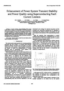
UPFC can be considered as the most interesting FACTS devices. It is able to control the active and reactive powers passing the line simultaneously and regulate its bus voltage. Fig. 1 shows the general configuration of UPFC. To install UPFC in the network a complex and detailed economical and technical examination affecting the network operation needs to be done. At the present most studies are based on the ability of this controller in transient and dynamic states in order to improve the stability of the network. However, the primary purpose of FACTS devices application is to use them in steady-state and control the power current in the power system. In order to study UPFC operation more accurately, a two-machine system is considered. In Fig. 2, Vpq is the improved synchronized voltage source which is made by UPFC in the main component frequency of the power system. This voltage has a controllable magnitude Vpq and an angle p ( 0:-::; p :-::; 2n). In UPFC array, the real power is supplied by
J. Faiz is with the S chool of Electrical Engineering,University of Tehran, Tehran 1439957131,Iran (e-mail:
[email protected]). Gh. S hahgholian and M. Torabyan are with the Department of Electrical Engineering, Islamic Azad University - Najaf Abad Branch. Esfahan, Iran (e-mail:
[email protected]) .
978-1-4244-5940-7110/$26.00©2010 IEEE
means of one of the end buses (for example the bus in the consumer side). In practical operations which are now performed, UPFC is made up of two voltage source converters as shown in Fig. 3. Therefore, UPFC structure which includes a parallel AC to DC voltage source converter and a series DC to AC voltage source converter connected by a DC capacitor. The series converter regulates the line active and reactive power by injecting an appropriate voltage in the line. The main purpose of the parallel converter is to supply the real power needed to compensate the power which is exchanged between the series converter and the network. The DC capaci tor also makes possible to exchange the real power between the two converters.
£-BIIS
In (4), 0 is the system transfer angle, PoCo), QOr are the real and reactive power of the uncompensated transmission system in an assumed angle respectively.
vsc-£
III.
Fig. 1: General configuration of UPFC
Vx �
Vpq
-----7
vs�
Vr
Vseff=Vs+Vpq
Ppq rv
rv
Fig. 2: UPFC operation in a two-machine system
V�� ��
__
-�V�' r +
___________________________
vc..
_ ____
The most important elements of UPFC are its switches. Besides the switches, UPFC contains two inductors and capa citors due to their capacity, and different characteristics are available and easy to determine. So, the only power restrictions and particularly the switching frequency of UPFCs are related to their switches. However, with present advances in power electronics devices, there is almost no limitation; the high power UPFC switches are responsible to the harmonics generated by nonlinear loads. There are two main characteristics for the power and frequency of UPFC switches. It is noted that UPFC needs a switch that could be tum-on and tum-off at any time. Thus, a single element such as thyristor cannot be used. Although there is circuits that can tum-off a thyristor by another one, however these circuits are used for a low switching frequency and not high frequency. The appropriate switches for this purpose are IGBT, GTO and IGCT. The main characteristics of these switches are the low losses in on and off states due to the thinness of the silicon layer, and operation at high frequencies in steady- and transient-modes. IV.
Fig. 3. Structure of UPFC
The transmitted power P and the reactive power provided by the consumer, is as follows: * V s + Vpq - Vr . P JQ r - Vr -----. '--'---_
(
_
Jx
-jQn
)
Jx
J
- Jx
Therefore, P and Qr are calculated as follows: P (o, p ) Qr(o,p)
==
=
Po (0) + Ppq (p)
QOr(o) + Qpq (p)
=
==
� sino X
VVpq X
�(1- coso) X
cos
(i ) (i )
VVpq X
2
+
sin
POWER QUALITY PARAMETERS IMPROVEMENT BY CONTROLLING UPFC SWITCHES
Voltage and current waveforms are assumed sinusoidal, and therefore the applied method for UPFC control is the sinusoi dal PWM in the voltage model. To improve UPFC operation, the on-line control method is applied. In this way, the voltage pattern is connected to the ground by phase signals. By combining these signals a sinusoidal voltage pattern is generated. In this case the modulating signal is defined as follows: 00
(1)
If Vpq=O, then (2) indicates the uncompensated system. Thus, if Vpq700, the overall real and reactive power may be written as follows: * * VV Vs - Vr � + P_'Q (2) . J r =Vr .
(
AN ApPROPRIATE CHOICE OF SWITCH FOR UPFC
p (3)
2
+
p
(4)
cot
(
Fig. 10. Three-phase voltage RMS before and after UPFC connection (voltage scale 0.26/div, time scale 0. 4 seconds/div)
Fig. 6. Over-voltage and dip in phase b before connecting UPFC (voltage scale 100/div, time scale 0.4 seconds/div)
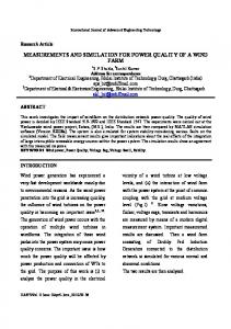
Also assume that the voltage dip and over-voltage happen respectively in phase c at 1.2 s and 1.5 s and each lasts for 50 ms. It is observed that UPFC could favorably compensate these cases. To understand this matter, a three-phase RMS system is introduced in Fig.! O. It clearly shows the appropria te operation of this controIler. It is seen that all occurred faults in three-phases are observable in the three-phase RMS
voltage as evidence for power quality. UPFC controller reduces the fault to a minimum level at the transmitter side in such a way that this RMS tends to its lowest fluctuations at its reference value. The curves for phase a current with and without UPFC are shown in Figs. 11 and 12 respectively.
..
..
m iii
�
.
.
Fig. 11. Phase
a
current before UPFC connection
(current scale 1. 8/div, time scale 0.4 seconds/div)
The main goal in the power system is reduction of the active power fluctuations and compensation of the reactive power. This can be achieved by connecting UPFC compensator. It is noted that the control method of UPFC has been designed based on a sinusoidal PWM. Amplitude of modulation signal (Mf) variation based on a sinusoidal waveform has been shown in Fig. 15. This factor changes with variation of voltage and hence can regulate the voltage. Variations of dc capacitor voltage have been presented in Fig. 16. One of the important parts of UPFC is the dc capacitor. Its swings level should not be high. It is observed here that this fluctuation tends to its minimum desirable value. Harmonic distortions can be simulated and examined. Fig. 17 shows the receiver side voltage, in which there is no controller. Fig. 18 exhibits THD voltage in the transmitter side with controller. On the other hand, the harmonic f th th distortions due to 3 d, 5 , and 7 with and without a compensator are indicated in Figs. 19 and 20 respectively. The simulation results show that UPFC controller is able to eliminate the harmonics in the system. It also improves the harmonic distortions in the entire system.
Fig. 12. Phase a current before UPFC connection (current scale 0.6/div, time scale 0. 4 seconds/div)
These Figures indicate that UPFC controller improves both voltage and current swings. Variations of reactive and active powers in the transmitter and receiver sides of the power system have been shown in Figs 13 and 14 respectively.
Fig. 15. Amplitude of modulation signal (modulation signal scale O.l/div, time scale 0. 4 seconds/div)
-
f
.,
I
..
I
.,
_.
..." -.
I\IIN:IJU,JVII J\NINII\N\J
\
�
.ri.. . "" .J.i.'fMMNW vvJ;v,""
Mr.'"
\
�
�.
"
'WI'
,-
Fig. 16. Variations of dc capacitor voltage (voltage scale 1.2/div, time scale 0.4 seconds/div)
Fig. 13. Active power before and after UPFC connection (active power scale l/div, time scale 0. 4 seconds/div) -
-
�
-,
-�
Fig. 14. Reactive powers after and before UPFC connection (reactive power scale l/div, time scale 0.4 seconds/div)
�/I�
Il � �
Fig. 17: THD voltage level without UPFC (voltage scale 0.07/div, time scale 0.4 seconds/div)
VII. REFERENCE
Fig. 18: THD voltage level with present of UPFC (voltage scale 0.03/div, time scale 0. 4 seconds/div) �,
�*
��
�...
�-
.
�
.....
.�
�
•
rd Fig. 19. 3 , 5th and 7th harmonic distortion levels of voltage without UPFC (harmonic distortion O.Ol/div, time scale 0. 4 seconds/div)
rd Fig. 20: 3 , 5th and 7th harmonic distortion levels of voltage with
UPFC (harmonic distortion O.OOl/div, time scale 0.4 seconds/div)
VI.
CONCLUSION
In this paper, importance of power quality was emphasized, completely studied and analyzed. To improve the power quality parameters in the power transmission system, UPFC controller was designed and the system was simulated following its application. UPFC control is designed in such a way that not only regulates the voltage but also regulates the current, active and reactive power. It can also reduce the harmonics in the system and improves the overall harmonic distortion level. It was designed as such that it does not cause high swings in the dc capacitor voltage as shown in the simulation results clearly.
[1) R.Natesan, G.Radman, "Effects of ST ATCOM, S S S C and UPFC on voltage stability",IEEE Trans. on Pow. S ys.,No. 4,pp. 546-550,2004. [2) S .Mishra,"Neural network based adaptive UPFC for improving transient stability performance of power system",IEEE Tran. on Neur. Netw., Vol. 17,No. 2,pp. 461-470,March 2006. [3) C.Collins, N.Watson, AWood, "UPFC modelimg in the harmonic domain", IEEE Tran. on Pow. Deli., Vol. 21, No. 2, pp. 933-938, Apri 2006. [4) S. Bhowmick, B. � N. Kumar, "An indirect UPFC model to enhance reusability of newton power-flow codes", IEEE Trans. on Pow. Del., Vol. 23,No. 4,pp. 2079-2088,October 2008. [5) S .M.Alamelu, R.P.K.Devi,"Novel optimal placement of UPFC based on sensitivity analysis and evolutionary programming", Jour. of Engi. And Appl., pp. 59-63,2008. [6) lV. Milanovic,YZhang, "Global minimization of financial losses due to voltage sags with FACTS based devices", IEEE Trans. on Pow. Deli., Vol. 25,No. 1,pp.298-306,January 2010. [7) G. S hahgholian, P.Shafaghi, S. Moalem, M. Mahdavian, "Damping power system oscillations in single-machine infinite-bus power system using a S TATCOM",IEEE/ICCEE,pp.130-134,Dec. 2009. [8) M.Noroozian, L.Angquist, M.Ghandari, G.Anderson, "Use of UPFC for optimal power flow control", IEEE Trans. on Power Delivery, vol. 12,pp. 1629-1634,1997. [9) M. Tumay, A M. Vural, K. L. Lu, "The effect of unified power flow controller location in power systems", Elec. Pow. and Ene. S ys., No. 26, pp. 561-569,2004. [10) L. Gyugyi, CD. S chauder, S .L. Williams, T.R. Reitman, D.R. Torgerson,A Edris,'The unified power flow controller: A new approach to power transmission control", IEEE Tran. on Pow. Del., Vol. 10,No. 2, pp. 1085-1097,1995. [II) S A Nabavi-Niaki, M.R. Iravani,"S teady state and dynamic models of unified power flow controller (UPFC) for power system studies", IEEE Tran. on Pow. S ys.,Vol. 11,No. 4,pp. 1937-19436,1996. [12) A L'Abbate, M. Trovato, C. Becker, E. Handschin,"Advanced steady state models of UPFC for power system studies", IEEE Tran. on Pow. Sys., Vol. 17, No. 4, 2002. [13) C.R. Fuerte-Esquivel, E. Acha, H. Ambriz-Perez, "A comprehensive newton raphson UPFC model for the quadratic power flow solution of practical power network", IEEE Tran. on Pow. S ys., Vol. 15, No. 1, pp. 102-109, Feb. 2000.