DESIGN AND SIMULATIONS OF INTERDIGITAL TRANSDUCERS FOR LAMB-WAVE BASED SHM SYSTEMS
MICHAŁ MAŃKA *, MATEUSZ ROSIEK, ADAM MARTOWICZ, TADEUSZ UHL, TADEUSZ STĘPIŃSKI Department of Robotics and Mechatronics Faculty of Mechanical Engineering and Robotics AGH University of Science and Technology, Cracow
[email protected]
Abstract Structural health monitoring systems have been constantly improved in the past decades. A complete system should consists of two main components: a network of sensors placed on monitored structure and a system of data analysis for its processing and interpretation. Sensors in a SHM system should be builtin to allow for continuous measurement in opposite to non destructive evaluation (NDE) methods where sensors are temporarily mounted on a structure only during measurements. One of the most promising type of the transducers dedicated for SHM systems are Interdigital Transducers (IDT) which are designed for ultrasonic Lamb wave monitoring. Mode selectivity, excitation strength, wave directivity, size and relatively low cost are the most important advantages of IDT. In presented paper after a short introduction of Lamb waves and SHM systems, the advantages and disadvantages of IDT are discussed. Next, the main aspects of designing a narrow band IDT are presented. As an example of the designing process, a transducer used for the excitation of the first antisymmetric mode (A0) in a thick aluminum plate was chosen. To verify the properties of designed transducers a FE model was built and then simulated in ANSYS Multiphysics software. In the final part of the paper obtained results are presented and discussed.
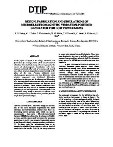
Introduction Structural health monitoring systems have been constantly improved in the past decades. A complete system should consists of two main components: a network of sensors placed on monitored structure and a system of data analysis for its processing and interpretation. Sensors in a SHM system should be built-in to allow for continuous measurement in opposite to non destructive evaluation (NDE) methods where sensors are temporarily mounted on a structure only during measurements. Nowadays there are many different types of the NDE techniques and some of them may be adapted for SHM systems. The NDE methods that may be adapted for SHM purpose are ultrasonic methods based on Lamb waves. Lamb Wave Fundamentals Based on Lord Rayleigh work Horace Lamb has discovered in 1917 new type of the waves that can exists in thin plates with parallel free boundaries. These type of the waves are called now “Lamb” Waves. Their main advantage is that they may travel over o long distance in different types of materials what allows for examination of large area with only few activators/sensors. Moreover Lamb waves allow for examination of entire cross section of the structure and are very sensitive for multiple defects identification [1]. Lamb Waves are created as the superposition of longitudinal and shear modes and may be excited as the symmetric and anti-symmetric waves (Fig.1)
Fig.1. Shape of the Lamb wave symmetric (left) and anti-symmetric (right) mode
Excited waves may be formulated as: for the symmetric wave :
tan(q * h) 4k 2 qp = 2 tan( p * h) (k − q 2 ) 2 Where: p2 =
for the anti-symmetric wave :
tan(q * h) (k 2 − q 2 ) 2 = tan( p * h) 4k 2 qp
(1)
ω2 c
2 L
− k 2 , q2 =
ω2 2 T
c
− k 2,k =
(2)
ω cp
h, k, cL, cT, cp, ω are the respectively: plate thickness, wave number, velocities of longitudinal and transverse modes, phase velocity and wave circular frequency.
There are many different methods/transducers for generating and receiving Lamb waves, below are listed only some of them: • Ultrasonic probes • Electromagnetic acoustic transducers (EMAT) • Laser • Piezoelectric elements • Interdigital Transducers (IDT) • Capacitive Micromachined Ultrasonic Transducers (CMUT’s) One of the most promising type of the transducers dedicated for SHM systems are Interdigital Transducers (IDT) which are designed for ultrasonic Lamb wave monitoring. Mode selectivity, excitation strength, wave directivity, size and relatively low cost are the most important advantages of IDT. Interdigital transducer (IDT) Interdigital transducers (IDT) are relatively novel construction in NDE but the origin of interdigital electrodes’ idea can be found in the patent of N. Tesla from 1891 [2]. Typical IDT transducer consists of three main layers (Fig.2.): bottom (ground) electrode, piezoelectric layer and top (phase) electrodes. Ground electrode is usually designed as the plate that covers majority of the transducer’s bottom surface. Piezoelectric layer may be made of piezoelectric polymer, like PVDF [3], piezoceramic material [4] or piezoceramic composite, MFC [5]. Material used for piezoelectric layer defines transducer’s properties like elasticity, maximal energy or frequency of generated waves. Third layer of the transducer is most significant for IDT because of the top electrodes’ patterns. Typically on the top surface are two sets of comb shapes’ electrodes. Distance between electrodes (finger separation) defines the length of the induced wave λ [6 ,7]. Other aspect of the IDT transducers is its directional generation of the wave. Signal is generated in direction perpendicular to the electrodes fingers and divergence of the wave is dependent on the fingers length. λ V+
L
VV+ VPiezoelectric Layer GND
Fig.2. Plane view and cross section of the IDT transducer
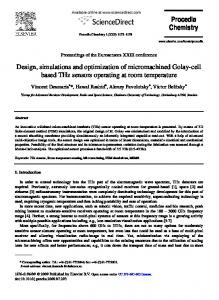
Transducer design Presented in the paper transducer is designed to excite specific mode in the 4mm thick aluminum plate. Desired mode may be excited by specific frequency. Most interesting excitation frequencies are frequencies where excited signals do not spread out in space. Such frequency can be found by analysis of the phase (Fig.3) and group (Fig.4) velocity dispersion curves for aluminum plate.
Fig. 3 Group velocity dispersion curves for 4mm aluminum plate
Fig.4 Phase velocity dispersion curves for 4mm aluminum plate
Generated waves will propagate with approximately same speed if the change rate of the group velocity is equal zero. Such situation may be observed at two points of the curve at maximum or minimum group velocity. For desired antisymetric (A0) mode, maximum group velocity at 329 kHz is chosen. Wavelength of the Lamb wave is calculated according equation:
λ=
Cp
(3) f Where Cp is the phase velocity and f is the frequency. For given example relationships takes form: 2468000 = 7.5mm λ= 329000 Other aspect of designing IDT transducers is directionality of the generating/sensing wave. It is connected with the fingers’ length (L) and can be approximately written as:
λ γ = arcsin( )
(4)
L
Where γ is the beam divergence angle. In presented transducer length of the fingers were 15 mm what gives divergence angle 30 deg. The layout and dimensions of the designed electrodes are presented in Fig 5a and Fig 5b. λ
Wt
Lg We
L
Wg
L= 15 mm
Wt= 1.9 mm We = 0.75mm Fig.5a. Top electrode pattern
λ= 7.5 mm
Lg = 28.2 mm Wg = 15 mm Fig.5b. Bottom electrode pattern
As the piezoelectric layer a 0.5 mm thick PZT patch from PIC151 material was chosen and electrodes were made of copper. Numerical simulations Numerical simulations were carried out for the designed transducer bonded centrally to an aluminium plate. The dimensions of the plate were: 500mm, 500mm and 4mm. Model of the structure was built in
Ansys Multiphysics software using 20-node brick finite elements. To simulate piezoelectric effect of the IDT transducer fully coupled transient analyses were performed. Time of simulations was set to be equal 80µs. Results obtained for the IDT transducer (Fig. 7, Fig. 9) were compared with simulations done for a simple PZT patch (Fig. 6, Fig. 8) of sizes 10mm, 10mm and 0.3mm, made of the same material. In both cases transducers were placed on the identical aluminium plates and supplied with the same electrical signals (five-cycle tone burst modulated with Hanning window).
A0 S0 Fig.6. Lamb waves generated by standard PZT patch (time=50µs)
S0
A0
Fig.7. Lamb waves generated by IDT transducer (time=50µs)
S0
A0
Fig.8. Out of plane displacements generated by standard PZT patch
S0
A0
Fig.9. Out of plane displacements generated by IDT transducer
Fig. 10 Frequency range of the generated Lamb wave
Sum of displacements generated using both types of piezoelectric transducers are presented in Fig. 6–7. Out of plane displacements evaluated in the point located horizontally in the middle of the plate and vertically 150 mm from the centre of it are presented in Fig. 8–9. It can be seen that conventional PZT patch generates uniform symmetric mode S0, while the amplitude of generated antisymmetric mode A0 is not identical in every direction. Amplitudes of both wave modes are comparable which can cause difficulties with processing of measured signals. Obtained results show that Interdigital Transducer generates directional waveform with dominant antisymmetric mode A0. The bandwidth of wave induced by IDT is more narrow which can reduce wave dispersion (Fig. 10). Moreover, the energy generated by IDT is focused on desired mode. Hence amplitudes of A0 mode excited by IDT can be approximately six times larger than amplitudes generated by standard PZT. Conclusions In this work a conception of designing Interdigital Transducer for Lamb wave generation was presented. Properties of the developed transducer were verified using Finite Element Method. It was proven that in comparison with conventional piezoelectric patch IDT transducer exhibits better performance in guided waves generation. Next step in the research will be manufacturing of designed transducers and experimental verification of the numerical results. Acknowledgements The work presented in this paper was performed within MISTRZ programme from Fundation for Polish Science. Bibliography 1. Rose, J. L. A vision of ultrasonic guided wave inspection potential. 2001, Proceedings of the Seventh ASME NDE Topical Conference NDE, Vol. 20. 2. Tesla, N. Electric Condenser. 464667 United States, 1891. 3. Bellan, Filippo, et al. A new design and manufacturing process for embedded Lamb waves interdigital transducers based on piezopolymer film. 123-124, 2005, A Sensors and Actuators, pp. 379-387. 4. Luginbuhl, Philippe, et al. Microfabricated Lamb Wave Device Based on PZT Sol-Gel Thin Film for Mechanical Transport of Solid Particles and Liquids. 4, December 1997, Journal of Microelectromechanical Systems, Vol. 6, pp. 337-346. 5. Williams, Brett R., et al. An Overview of Composite Actuators with Piezoceramic Fibers. Los Angeles : s.n., 2002. 20th International Modal Analysis Conference. pp. 421-427. 6. Monkhouse, R.S.C., Wilcox, P.D. and Cawley, P. Flexible interdigital PVDF transducers for the generation of Lamb waves in structures. 35, 1997, Ultrasonics, pp. 489-498. 7. Monkhouse, R.S.C., et al. The rapid monitoring of structures using interdigital Lamb. 9, 2000, Smart Materials and Structures, pp. 304-309.