CHAPTER 2 : MODEL OF THE ELECTROSTATIC SEPARATOR ... underlying the
process of electrostatic separation that goes on in the separation chamber.
CHAPTER 2 : MODEL OF THE ELECTROSTATIC SEPARATOR 2.1. Population Balance Model 2.1.1. Introduction: The objective of the development of this model is to understand the mechanics underlying the process of electrostatic separation that goes on in the separation chamber. The removal of ash and pyrites from the coal samples plays an important role in determining the recoveries and the percentage of pure coal. Thus, it may be possible to optimize the different parameters involved in the process on the basis of both the recovery and the percentage purity. The separation is based on the idea of differential charging of the coal and the impurities and the subsequent separation based on the attraction or repulsion to the corresponding electrodes. In this case, the model gives a brief overview of how the process occurs and how simulation may be done with the model.
The model is a
population balance model that studies the population of particles in concern. The various parameters that describe the electrostatic process play a role in deciding the population of the particles inside the separation chamber. This model is a simplified description of the process and tries to explain basic transport mechanism, the influence of the different forces under which the particles are attracted to the two electrodes. 2.1.2. Process Description: The process of separation of the fine particles is shown in Figure 2.1.1. The system shows the coal and ash particles in different symbols and their corresponding charges. On passing through a tribocharger, the coal particles take a positive charge and the ash and the sulfur particles take a negative charge (Finseth et al.). As a result, the coal moves towards the negative electrode and the impurities move towards the positive electrode. In the development of the model, a very skeletal structure of the system has been considered which are sufficient to understand the mechanism.
13
-
+
Coal particle Ash/sulfur particle Vx θ
Vz
_
+ θ
x y z
Figure 2.1.1 Experimental Model for Analysis 2.1.3. Model Description: The general microscopic PBM: J . . dψ d d d d + (Vxψ ) + (Vyψ ) + (Vzψ ) + ∑ (Vjψ ) + D− A = 0 dt dx dy dz j =1 dζ j
I
II
III
IV
V
(2.1.1)
VI VII
where, ψ is the population characteristic (in this case the grade of the sample being used), Vx, Vy, Vz are the velocities of the particles in the x, y and z directions. The last two terms in the equation above correspond to the disappearance and appearance of the particles. Some assumptions were made in order to better understand the mechanism and make the approach more simplistic. There is just one property of interest, charge 'q'. There are no continuous or discrete changes in charge with respect to time. This also implies that the sample is well mixed. Under the assumptions made, the system was completely mixed in the 'y' direction, i.e,
14
d (Vyψ ) = 0. dy . There is no sudden appearance of particles ( A = 0).
(2.1.2) At time 't'=0, there is no
disappearance of particles. The disappearance is caused by electrostatic separation, where the separation rate is given by rs(q). rs(q)=Vs (q)ψ(q,z)
(2.1.3)
Here Vs (q) is the transport rate. It is a function of the feed rate of particles into the separator unit. Since the separation rate is negligible compared to the other terms, this term may be neglected. The system is assumed to be operating at steady state, i.e., d (ψ ( t, q, z)) = 0 dt
(2.1.4)
The entire system is believed to be operating under the conditions of a varying electric field and so the velocity in x and z directions are functions of z, i.e., d (Vzψ (q, z )) ≠ 0 dz
(2.1.5)
Finally the force acting the x-direction is a function of x but the change is very small because of the distance and hence can be neglected when compared with the other terms. From the above assumptions, the various terms of the equation are as follows: Terms I
=0
II =
d [Vxψ (q, x, z )] dx
III = 0 IV =
d (Vzψ (q, x , z )) dz
And terms V, VI and VII can be neglected.
Velocity Vz : In order to derive an equation for the settling velocity Vz, m
dVz = Fg + Fe sin θ dt
where, m is the mass of the particle
15
(2.1.6)
Fg is the force due to gravity Fe is the electrostatic force of attraction due to charge on particles m=
π 3 π δ ρ p ; Fg = δ 3 ρ p g ; Fe = E .q 6 6
(2.1.7)
where E is the electric field Therefore, dVz sinθ = g + 6 E .q 3 dt πδ ρ p
(2.1.8)
Integrating both sides we get, sinθ Vz = g + 6 E .q t 3 πδ ρ p
(2.1.9)
Substituting this in the equation describing term IV, we get Term IV =
d sinθ ψ ( q , x , z ) g + 6 E .q 3 t dz πδ ρ p
(2.1.10)
Also, z
sin θ =
x2 + z2
Therefore, Term IV =
⇒
g +
d z 1 ψ ( q , x , z ) g + 6 E .q t 3 dz x 2 + z 2 πδ ρ p
d E .q t (ψ (q , x , z )) 3 dz x 2 + z 2 πδ ρ p 6z
�(A )
1
d + ψ (q , x , z ) g + dz
(2.1.11)
6z 1 E .q t 3 x 2 + z 2 πδ ρ p
16
�(B )
(2.1.12)
(B) = ψ (q , x , z )t
=ψ (q , x , z )t
=ψ (q , x , z )t
z
6
πδ 3 ρ p 6
πδ 3 ρ p
Term IV = g + + ψ (q , x , z )t
x
2+ 2
z
q
d z E .q πδ 3 ρ p dz x 2 + z 2 6
dE d z 6 E .q + ψ (q , x , z )t dz dz x 2 + z 2 πδ 3 ρ p
x2 dE 6 + ψ (q , x , z )t q E .q 3 πδ 3 ρ p x2 + z2 2 x 2+ z 2 dz z
(
)
(2.1.13)
(2.1.14)
d E .q t (ψ (q , x , z )) 3 dz x 2 + z 2 πδ ρ p 6z
6
πδ 3 ρ p
1
dE x2 6 + ψ (q , x , z )t q E .q 3 πδ 3 ρ p x2 + z 2 2 x 2+ z 2 dz z
(
)
(2.1.15)
Velocity Vx: Similarly, in order to derive an equation for the settling velocity Vx, m ⇒
dVx = Fe cosθ dt
dVx 6 = E .q cos θ dt πδ 3 ρ p
(2.1.16) (2.1.17)
Integrating both sides we get, Vx =
6 cos θ
πδ 3 ρ p
E .q.t
(2.1.18)
But, cosθ =
x x2 + z2
(2.1.19)
Therefore, Vx =
6x
1
3 x + z πδ ρ p 2
2
E .q.t
Substituting the above in the equations for Term II, we get,
17
(2.1.20)
d 6 x + E .q .t 2 2 dx πδ 3 ρ p x +z d 6x 1 . E .q .t (ψ (q , x , z )) 3 dx x 2 + z 2 πδ ρ p
ψ (q , x , z ) Term II =
( =ψ (q , x , z )
6
πδ ρ p 3
E .q .t
=ψ (q , x , z )
)
d x 6 + 3 dx x 2 + z 2 πδ ρ p +
6z 2
(x2 + z 2 ) 2 πδ 3
+
6
πδ ρ p 3
t 3
ρp
(2.1.21)
ψ (q , x , z ) 6
E .q +
6
πδ ρ p 3
3
πδ ρ p
tψ ( q , x , z )
(x
x
(x2 + z 2 )
xq 2
+ z2
)
x
(x
xq 2
+ z2
)
d (ψ ( q , x , z )) dx
dE dx
(x2 + z 2 )
.
E .q .t
E .q .t
(2.1.22)
d (ψ (q , x , z )) dx
dE dx
(2.1.23)
The Final Model becomes, 6ψ (q , x , z )
z2
(x 2 + z 2 )3 2
πδ 3 ρ p g +
E .q +
x
6
(x 2 + z 2 )
πδ 3 ρ p
d 6 E .q (ψ (q , x , z )) + ψ (q , x , z ) 3 3 dz πδ ρ p x 2 + z 2 πδ ρ p xq dE x2 6ψ (q , x , z ) 6 + + ψ (q , x , z ) E .q 3 πδ 3 ρ p πδ 3 ρ p x2 + z2 2 x 2 + z 2 dx 6z
1
(
)
E .q
d (ψ (q , x , z )) dx
z
(x2 + z 2 ) =0
q
dE dz (2.1.24)
Simplifying further, we get 6ψEq
(
x2 + z 2
)
πδ ρ p 2 x + z2 2 3
+
3
dE dψ E +ψ dx x 2 + z 2 dx
6 x.q
πδ 3 ρ p
(
)
dE dψ dψ E +ψ +g =0 dz dz x 2 + z 2 dz
6 zq
πδ 3 ρ p
+
(
)
where, ψ is the same as ψ(q,x,z).
18
(2.1.25)
⇒ 6ψEq
x2 + z2
(x
2
+ z2
(x
+ g πδ 3 ρ p
2
)
dE dE dψ dψ 6 zq E + 6 xq E +ψ + +ψ dx dz dx dz
+ z2
dψ =0 dz
)
(2.1.26)
Let A = πδ 3 ρ p . From the physical model in the subsequent section, E= ⇒ where, k = 1
4πεε 0
kq x + z2
(
2
− 2x dE = kq 2 2 dx x + z
(
)
dE − 2kqz = and dz x2 + z 2 2 2
)
(
)
(ε , ε 0 are the permittivitties of the air and free space).
6xkq 2 dψ 12x 2 q 2 kψ 6zq 2 k dψ 12z 2 q 2 kψ − ∴ + 2 − + 2 2 2 2 x + z 2 dx x + z 2 dz x2 + z2 x2 + z2 x2 + z2 dψ + gA x 2 + z 2 =0 dz
(
6ψkq 2
) ( ( )
)
) (
(
)
(
)
(2.1.27)
Simplifying further, the final population balance model equation is, 6kq 2 dψ dψ 6q 2 kψ x +z − + gA dz x 2 + z 2 x 2 + z 2 dx
(
)
(
)
(x
2
+ z2
) dψ = 0 dz
(2.1.28)
Boundary Conditions 1. At the top of the separator unit, ψ(q,x,z) = ψfeed 2. At t = 0, and the top of the separator unit, velocity Vz = feed air velocity. 3. For a positive electrode, there is a force of attraction to the negatively charged particle but a force of repulsion to the positively charged particle. So the force changes sign corresponding to the charge induced on the particle. 4. E is known at the z=0 plane. 5. k is a known parameter. 6. When the flow of particles reach a particular plane of ‘z’ the particles are assumed to
19
be assumed to be out of the system and the distribution of ψ(c,x,z) is determined there. 2.1.4. Results: The idea behind development of this model is to understand the distribution of the particles on either side of the flow splitter and finding the grade and recovery of the coal that is obtained. The final model gives a clear picture of the distribution of ψ(c,x,z) for any plane of z since the other parameters can either be determined from mathematical formulas or from knowledge of the material properties. The distribution is determined by substituting various values of ‘x’ for a particular value of ‘z’. 2.1.5. Discussion: 1. No disappearance term is considered in the model, since when the particles reach a particular value of ‘z’ they are assumed to be out of the system. The kinetics is prevailed over by the transport phenomena, i.e., the distribution of particles is more important compared to the kinetics of disappearance. 2. The force due to gravity, Fg in the equations for determining the settling velocity in the ‘z’ direction (Vz) takes into account the initial velocity of air that is pumped in with the particles. The force acts with an acceleration for the particles already with an initial velocity. 2.1.6. References: Adel, G.T., Class notes, Particulate Process Modeling, Spring ‘96 Finseth, D., Newby, T. and Elstrodt, R., "Dry Electrostatic Separation of Fine Coal", Proc. of the 9th Korea-U.S. Joint Workshop on Coal Utilization Technology, October 1992.
20
2.2 Prediction of the Particle Trajectory 2.2.1 Introduction: The particle trajectory is an important feature in determining the effect of field on the motion of the particle. Ideally, the particle (charged positive or negative) should follow a trajectory that is just enough to move it away from the similarly charged electrode, towards the oppositely charged electrode. The parameters that come into play while establishing the path followed by a particle include charge induced on the particle in the tribocharger, particle size and position of the feeder. The ability of a particle to move towards the correct electrode helps in establishing the good grade-recovery curves. The force balance equations developed in the population balance model (described earlier in the chapter) define the nature of forces acting on the particles due to the effect of the varying electric field (open-gradient separator) and gravity. In the actual separator used in the project work, one was a positively charged electrode and the other connected to ground. Therefore, a negatively charged particle is just subjected to attractive forces (from the positive electrode) while the positively charged particle is under the influence of repulsive forces (again from the positive electrode). The electrode connected to ground provides neither an attractive force nor a repulsive force. It provides a surface for the positively charged particles to collect. As a part of the exercise of predicting the path taken by a particle, the force equations mentioned earlier are used. This model was aimed to develop the paths taken for four different sizes of particles, four different charges induced on a particular size and four different feed positions.
2.2.2 Model Description: Figure 2.1.1 describes the motion of the particle based on their relative charges with the electrodes. The same convention of axes was used for the following equations of forces. A negatively charged particle was considered while describing the forces acting on the particles. If a positively charged particle were to be considered, the electrostatic forces would be repulsive, instead of being attractive. The process was described in very small time intervals 'δt' and in this interval the initial velocity is 'u' and the final velocity, 'v'. In this infinitesimally small segment, the electrostatic force was assumed to be a constant.
21
Force acting on the negatively charged particle in the z-direction, m.a z = Fe sinθ
(2.2.1)
where, 'az' is the resultant acceleration of the particle in the z-direction, m is the mass of the particle, 'Fe' is the force due to electrostatic attraction and θ is the angle described in the Figure 2.1.1. It will be interesting to note that the force due to gravity was considered in determining the initial velocity of the particle entering the field (described later). Considering the size range of the particle, the only force influences the particle in the electrostatic field is the force due to electrostatic attraction. m.a z = E .q sinθ
(2.2.2)
q (mq d ) az = e sin θ 4πεε 0 r 2 m
(2.2.3)
Therefore,
And, m=
π 3 δ ρ p , q = qd .m 6
q e = V .4πεε 0 l d Substituting the above in in Eq 2.2.3, we get q az = V .ld d2 sinθ r
(2.2.4)
'qd' is the charge per unit mass of the particle, 'ε' is the permittivity of air, 'ε0' is the permittivity of free space, 'V' is the voltage applied to the electrode, 'ρp' is the density of the particle, 'δ' is the diameter of the particle and 'r' is the distance of the particle from the center of the electrode. z = uzt +
1 azt 2 2
vz = u z + a zt
(2.2.5) (2.2.6)
Here 'z' is the distance traveled by the particle in the vertical direction under the influence of the acceleration in the z-direction. Th initial velocity of the particle (entering the electrostatic field) in the z direction was taken to be the terminal velocity which was attained by using Stokes' law described below.
22
Fg = 6πη .rp .u
(2.2.7)
m.g 6πη .rp
(2.2.8)
u=
where, 'u' is the terminal velocity of the particle, 'η' is the co-efficient of viscosity of the medium (air), 'rp' is the radius of the particle being considered, 'm' is the mass of the particle described earlier and 'g' is the acceleration due to gravity. At the end of each segment, the acceleration is computed due to a change in the electrostatic force and all the subsequent steps are repeated.
After each set of
computations, 'v' of the earlier step becomes the 'u' of the next step and the new 'z' is the sum of the old 'z' and the incremented component. In the x-direction, only the electrostatic force caused a movement in the particle in that direction, which results in m.ax = Fe cos θ
(2.2.9)
Here, 'ax' is the resultant acceleration of the particle in the x-direction (horizontal direction). ax =
E .q cos θ m
(2.2.10)
Substituting the values of E and q in the above equation, ax =
Vld .qd r2
cos θ
(2.2.11)
Taking equations of motion in x-direction, x = uxt +
1 axt 2 2
(2.2.12)
And, vx = u x + a xt
(2.2.13)
A procedure similar to the one used in computation of 'z' is also done for 'x'. Following each set of computations, 'r' was calculated again using the equation given below. r = z2 + x2 The simulations for the above model were conducted in Excel spreadsheets by
23
(2.2.14)
assigning values to the different constants mentioned above. 2.2.3 Boundary Conditions: Maximum 'z' that can be reached before a particle can reach the bottom of the separator = 12 inches. Maximum 'x' that can be reached before a particle can reach the side of the separator = 8 inches. Initial angle θ = tan-1(12/8) Subsequent θ = tan-1 ((12-z)/(8-x)) ρp = 1.6 g/cc δ = Aperture size of the mesh from the Tyler mesh series V = 50000 volts η = 2.6 x 10⁻⁶ SI units Values of particle charge used for the charge dependency simulation were 41,50,60 and 70 micro coulombs/kg. Values of particle size used for the size dependency simulation were -65 + 100 mesh,-100 + 150 mesh, -150 + 200 mesh, -200 + 270 mesh. Values of 'x' used for the feed position dependency simulations were 0,1,2,3, inches from the center of one electrode (the positive electrode). 2.2.4 Results: Figure 2.2.1 shows the effect of induced particle charge on the trajectory of the particle, where ‘Ve’ stands for the vertical distance from the line of electrodes and ‘Hcs’ stands for the horizontal distance from the center of the separator. The greater the charge, the sooner the particle reaches the electrode. This particular plot is expected because the greater the charge, the greater is the attractive force for the particle and hence sooner it reaches the favorable electrode. Since this result is expected, the plot validates the model and the simulation. This set of simulations were run on -200 + 270 mesh particles and fed at the center of the separator (x=0). The phrase "sooner" implies that the maximum value of 'x' is reached at the least value of 'z'. In the case of this separator, the maximum value of 'x' is the plane of the edge of the drum electrode (which is x=2). It can be seen that particles have a narrow range of deviation from the center of the presence of splitter at the bottom of the chamber.
24
12
qd
10
4.1 x 10⁻⁵ C/kg 5 x 10⁻⁵ C/kg
Ve (inches)
8
6 x 10⁻⁵ C/kg 7 x 10⁻⁵ C/kg
6
4
2
0 0.0
0.1
0.2
0.3
0.4
0.5
0.6
0.7
Hcs (inches)
Figure 2.2.1. Trajectory of particles (200 to 270 mesh) of different charges.
25
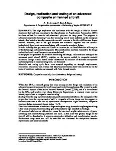
Figure 2.2.2 shows the effect of the particle size on the trajectory of the particles. The finer the particles, better they separate. This can be explained by the greater charge that is carried by the finer particles which results in greater attractive forces. The finer particles tend to acquire more charge because of greater surface area for the same weight of sample. Also due to the presence of higher gravitational force, the coarser particles attain a higher terminal velocity which influences a faster motion down. This results in a steeper curve for the coarse particles when compared to the fine particles. The smallest particle (-200+270 mesh) has a charge density of 41 micro C/kg and the largest particle (65+100 mesh) has a charge density of 22.5 micro C/kg. As illustrated in the Figure 2.2.1, charge has a significant impact on the trajectory of the particle and this being compounded with the terminal velocity (in effect the initial velocity of the particle entering the field), the finer particles have a better separation than the coarser particles, mathematically. In Figure 2.2.3, the particles of different sizes were assigned same charge density. Though this is not possible in reality, this was plotted to emphasize on the fact that both charge density and particle size are important in predicting the trajectory of the particle. It was observed that the smaller particles deviated further than the larger particles towards the electrode. Figure 2.2.4 shows the effect of feeder position on the trajectory of the particles. The closer the particles are fed towards the favorable electrode, the sooner they move towards the electrode. A similar result can be expected for the negatively charged particles but for the positively charged particles that are fed at the same position would have to travel a longer 'z' to reach the other electrode. The idea of moving the feeder closer to an electrode is not a straight-forward theory and has to be better analyzed by checking the grade-recovery curves of the corresponding samples. 2.2.5 Conclusion: A mathematical and physical means of predicting the particle trajectory was successfully established. This could help in fixing certain parameters to achieve a better separation of coal and ash using the triboelectrostatic separation technique. The finer particles acquire greater charge density compared to coarse particles due to the increased surface area available for storing charges.
26
12
mesh 65 to 100 100 to 150 150 to 200 200 to 270
Ve (inches)
10
8
6
4
2
0 0.0
0.1
0.2
0.3
0.4
0.5
0.6
0.7
Hcs (inches)
Figure 2.2.2. Trajectory of different size particles on being charged in a regular method.
27
12
mesh 65 to 100 100 to 150 150 to 200 200 to 270
10
Ve (inches)
8
6
4
2
0 0.0
0.1
0.2
0.3
0.4
0.5
0.6
0.7
Hcs (inches)
Figure 2.2.3. Trajectory of particles when same charge density (41 microC/kg) is applied to particles of different sizes.
28
12
mesh 65 to 100 100 to 150 150 to 200 200 to 270
10
Ve (inches)
8
6
4
2
0 0.0
0.1
0.2
0.3
0.4
0.5
0.6
0.7
Hcs (inches)
Figure 2.2.4. Trajectory of particles for particles of same size (-200 +270 mesh) for varying positions of the feeder (0, 1, 2, 3 inches) from the center of the separator.
29
As a result, even if the different sizes of particles are charged for the same duration, the finer particles acquire greater charge density. Hence, mathematically it can be proved that fine particles separate better than particles of similar structure but coarser.
30