THPCH103
Proceedings of EPAC 2006, Edinburgh, Scotland
DESIGN AND TESTING OF Gproto BUNCH-BY-BUNCH SIGNAL PROCESSOR ∗ D. Teytelman† , C. Rivetta, D. Van Winkle, R. Akre, J. Fox, A. Krasnykh, SLAC, Stanford, USA A. Drago, LNF-INFN, Frascati, Italy J. Flanagan, T. Naito, M. Tobiyama, KEK, Tsukuba, Japan Abstract Ethernet
A prototype programmable bunch-by-bunch signal acquisition and processing channel with multiple applications in storage rings has been developed at SLAC. The processing channel supports up to 5120 bunches with bunch spacings as close as 1.9 ns. The prototype has been tested and operated in five storage rings: SPEAR-3, DAΦNE, PEP-II, KEKB, and ATF damping ring. The testing included such applications as transverse and longitudinal coupled-bunch instability control, bunch-by-bunch luminosity monitoring, and injection diagnostic. In this contribution the prototype design will be described and its operation will be illustrated with the data measured at the above-mentioned accelerators.
Linux PC
USB driver USB interface
Trigger
EPICS IOC Temperature and supply monitoring
Clock (500+ MHz)
CLK/2
Input
ADC MAX104
16
FPGA
DAC
XC2V4000
MAX5886
Output
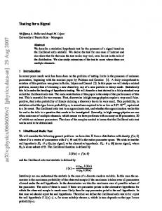
Figure 1: The Gproto block diagram.
SYSTEM ARCHITECTURE INTRODUCTION Most modern lepton storage rings operate above the dipole coupled-bunch instability thresholds in transverse and longitudinal planes. Digital bunch-by-bunch feedback systems have become in the last 15 years a ubiquitous solution for controlling such instabilities [1, 2]. In this paper we describe a prototype (Gproto) of a highly flexible bunch-by-bunch signal processing channel. The Gproto provides real-time baseband signal processing at the sampling frequencies up to 550 MHz. Flexibility is achieved via the use of a field-programmable gate array (FPGA) for all demultiplexing and signal processing tasks. The Gproto can be configured to support bunchby-bunch feedback as well as a host of bunch-by-bunch beam and collider diagnostic functions. The Gproto supports reconfiguration of the processing harmonic number to adapt to a particular storage ring. Feedback controller topology can also be modified allowing one to use finite or infinite impulse response (FIR or IIR) filters of different orders. For longitudinal feedback applications which often demand controller impulse response persisting for tens of revolutions, downsampling can be used to more efficiently utilize the computational resources. In the most challenging case of KEKB rings with 509 MHz RF frequency and 5120 bunches the Gproto executes an equivalent of 4 × 10 9 integer multiply/accumulate operations per second. ∗ Work supported by U.S. Department of Energy contract DE-AC0276SF00515 †
[email protected]
3038
The block diagram of the prototype is shown in Fig. 1. The heart of the system is a Virtex-II FPGA. The FPGA receives the high-speed digitized data from the 1 GSPS 8-bit analog-to-digital converter (ADC). Feedback output correction is converted to baseband analog signal by 500 MSPS 12-bit digital-to-analog converter (DAC). Both the ADC and the FPGA are mounted on evaluation boards from Maxim Semiconductor and Xilinx respectively. The use of these evaluation boards shortened the development cycle of the prototype to one month. For interconnect between the ADC and the FPGA standard ribbon cable was used to carry fully differential digital data. That interface has been tested to transfer clock rates up to 300 MHz which corresponds to 600 MSPS ADC conversion rate. In transverse feedback applications the Gproto is combined with a front-end that converts raw BPM signals to baseband bunch positions. A typical back-end set-up consists of two power amplifiers differentially driving a set of striplines. The Gproto provides complementary low-level DAC outputs for simple interfacing. The DAC output structure is optimized for wide bandwidth, achieving 240 ps rise and 360 ps fall times for the full-scale swings. Any accelerator instrumentation and diagnostic system to be fully usable requires some form of the operator interface. The Gproto utilizes an EPICS softIOC running under a standard Linux distribution. The softIOC communicates with the hardware via USB interface, previously developed for low group-delay woofer application in PEP-II [3]. The Gproto user interface, built using edm display manager, provides operator with control functions for feedback configuration, system and beam diagnostics. Feedback control functions include two selectable sets of FIR
06 Beam Instrumentation and Feedback T05 Beam Feedback Systems
Proceedings of EPAC 2006, Edinburgh, Scotland
THPCH103
EXPERIMENTAL RESULTS Within 6 months of its creation the Gproto has been tested in 5 storage rings: SPEAR-3, DAΦNE, PEP-II, KEKB, and the ATF damping ring. Here selected results of these tests are presented.
Longitudinal Feedback
filter coefficients, shift gain, and one-turn delay. System diagnostics include RF clock loss and output saturation detectors, supply voltage and component temperature monitoring. The Gproto includes a built-in DAC test pattern generator which allows one to test the performance of the output section and also to properly match the DAC fullscale and the saturation level of the power amplifier. Integrated beam diagnostics in the Gproto use the internal FPGA memory to acquire 128–240 kB of beam data. The acquired waveform is read out via the USB at an update rate up to 2 Hz. A set of IOC subroutines postprocesses the data in the real-time and provides four concise plots displayed in the waveform panel as shown in Fig. 2. The four plots are: bunch-by-bunch mean and RMS of bunch oscillations, time-domain signal of a bunch with the largest RMS. The last plot is obtained by performing the FFT on each of the bunches and quadratically averaging the resulting spectra. This plot aliases coupled-bunch eigenmodes to a frequency span from DC to ω rev /2. Such a spectrum allows the operator to very quickly check how well the system damps the coupled-bunch motion. The snapshot in Fig. 2 shows the vertical motion in the PEPII LER acquired on an external trigger synchronized with the injection. The plot clearly shows the large RMS value of the injected bunch as well as the smaller perturbation of the stored beam by the injection kicker bump. The max RMS plot shows the time-domain motion of the injected bunch, while in the spectrum a wideband excitation around the vertical betatron frequency of 56 kHz can be seen.
Transverse Feedback In Fig. 4 a grow/damp measurement performed in the DAΦNE positron ring is shown. This measurement was performed with a 100-bunch train and a 20-bunch gap. Plot a) shows the bunch oscillation amplitude increasing along the train with all the bunches participating in the exponential growth and, once the feedback loop is closed, damping. In plot b) the bunch motion is shown in the even-fill eigenmode basis showing several dominant low-frequency modes. By fitting a complex exponential to the growing and damping sections of the transient one can estimate the open and closed-loop modal eigenvalues [4].
Open loop Closed loop
1
10
0
Counts
Figure 2: Beam data display for the LER.
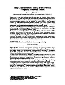
The Gproto has been tested in the Accelerator Test Facility (ATF) damping ring as a longitudinal feedback channel. In order to create the 90 degree phase shift at the synchrotron frequency of 10 kHz the feedback controller needs to have impulse response lasting around one period of that frequency, i.e. 100 μs corresponding to 216 turns. Since a 216-tap FIR implementation was unfeasible in the Gproto, downsampling by 16 combined with a 16-tap FIR was used for a filter spanning 256 turns. A comparison between the open and closed-loop quadratically averaged bunch spectra is presented in Fig. 3. Closing the longitudinal feedback loop suppresses the unstable synchrotron motion and reduces the oscillation due to the various noise sources within the ring RF system.
10
−1
The postprocessing reduces the two-dimensional matrix of bunch positions versus turns to several one-dimensional vectors. Next, from these vectors we derive a set of six scalar metrics which encapsulate the information about beam stability, excitations, etc. The scalar values are: overall mean and RMS, RMS of the most excited bunch, peakto-peak amplitude, and, finally, the frequency and the amplitude of the largest spectral peak.
06 Beam Instrumentation and Feedback T05 Beam Feedback Systems
10
0
2
4
6
8 10 Frequency (kHz)
12
14
16
Figure 3: A comparison of open-loop (blue) and closedloop (red) longitudinal spectra in the ATF damping ring.
3039
THPCH103
Proceedings of EPAC 2006, Edinburgh, Scotland
Figure 4: A horizontal grow/damp measurement in DAΦNE positron ring. 120
The integrated real-time beam diagnostics in the Gproto open a large field of applications of the architecture in storage rings. The externally triggered recording capability, illustrated in Fig. 2 has been used in PEP-II HER and LER to optimize timing and amplitudes of the injection kickers, leading to reduced beam perturbation and lower injection backgrounds. The Gproto has also been tested in PEP-II as a bunch-bybunch luminosity monitor. In this application the feedback FIR filter was replaced by an IIR turn-by-turn integrator with a 4000 turn time constant. The output of the integrator was stored in the FPGA memory and polled at 2 Hz rate to produce an updating display. Due to parasitic nature of the testing the digitized signal was derived from an output of a discriminator and required multi-turn integration. In Fig. 5 the Gproto luminosity data is shown for section of the PEP-II bunch train. The empty mini-train gaps show zero luminosity, as expected. Note the systematically lower luminosity of the last bunch in each mini-train.
100
SUMMARY A bunch-by-bunch processing channel has been prototyped and tested at five accelerator facilities. During the tests the prototype was used to stabilize horizontal, vertical, and longitudinal coupled-bunch instabilities, to optimize injection, to provide bunch-by-bunch luminosity information. The built-in diagnostic capabilities allow the user to quickly set-up the system and provide a way for routine monitoring of system performance. Two prototype chassis have been built and tested with one unit operating as a horizontal bunch-by-bunch feedback channel in DAΦNE positron ring since October 2005. At this time an integrated processing channel is under development for multiple ap-
3040
Luminosity (arb. units)
Beam Diagnostic Applications
80 60 40 20 0 840
860
880 900 Bunch number
920
940
Figure 5: Luminosity information from the Gproto for a section of PEP-II bunch train. plications in PEP-II and KEKB machines.
REFERENCES [1] M. Tobiyama and E. Kikutani, “Development of a high speed digital signal process system for bunch-by-bunch feedback systems,” Phys. Rev. ST Accel. Beams, vol. 3, p. 012801, 2000. [2] C. G. M. Lonza, D. Bulfone, “Digital processing electronics for the ELETTRA transverse multi-bunch feedback system,” in Accelerator and Large Experimental Physics Control Systems, (Trieste, Italy), pp. 255–257, Comitato Conferenze ELETTRA, 1999. [3] D. Teytelman, D. Van Winkle, and J. Fox, “Operating performance of the low group delay woofer channel in PEP-II,” in Proceedings of the 2005 Particle Accelerator Conference, (Piscataway, NJ, USA), pp. 1069–1071, IEEE, 2005. [4] D. Teytelman, Architectures and algorithms for control and diagnostics of coupled-bunch instabilities in circular accelerators. PhD thesis, Stanford University, 2003. SLAC-R-633.
06 Beam Instrumentation and Feedback T05 Beam Feedback Systems