IOP Conference Series: Materials Science and Engineering
Related content
PAPER • OPEN ACCESS
Design Automation Using Script Languages. HighLevel CAD Templates in Non-Parametric Programs To cite this article: R. Moreno and A. M. Bazán 2017 IOP Conf. Ser.: Mater. Sci. Eng. 245 062039
- Automation in the Teaching of Descriptive Geometry and CAD. High-Level CAD Templates Using Script Languages R. Moreno and A. M. Bazán - DEVICES FOR OBSERVATORY AUTOMATION R. K. Honeycutt, B. R. Adams, D. J. Swearingen et al. - AUTOMATION OF A COMMERCIAL ASTRONOMICAL TELESCOPE Anthony Mallama
View the article online for updates and enhancements.
This content was downloaded from IP address 191.101.97.63 on 05/11/2017 at 13:25
WMCAUS IOP Publishing IOP Conf. Series: Materials Science and Engineering 245 (2017) 062039 doi:10.1088/1757-899X/245/6/062039 1234567890
Design Automation Using Script Languages. High-Level CAD Templates in Non-Parametric Programs R. Moreno1, A. M. Bazán2 1
University of Granada, Dpto. Expresión Gráfica, E.T.S. Ingeniería de Edificación, 18071 Granada, Spain 2 UPM, Dpto. Ingeniería Civil: Construcción, E.T.S. Ingeniería de Caminos, Canales y Puertos, 28040 Madrid, Spain
[email protected] Abstract. The main purpose of this work is to study the advantages offered by the application of traditional techniques of technical drawing in processes for automation of the design, with non-parametric CAD programs, provided with scripting languages. Given that an example drawing can be solved with traditional step-by-step detailed procedures, is possible to do the same with CAD applications and to generalize it later, incorporating references. In today's modern CAD applications, there are striking absences of solutions for building engineering: oblique projections (military and cavalier), 3D modelling of complex stairs, roofs, furniture, and so on. The use of geometric references (using variables in script languages) and their incorporation into high-level CAD templates allows the automation of processes. Instead of repeatedly creating similar designs or modifying their data, users should be able to use these templates to generate future variations of the same design. This paper presents the automation process of several complex drawing examples based on CAD script files aided with parametric geometry calculation tools. The proposed method allows us to solve complex geometry designs not currently incorporated in the current CAD applications and to subsequently create other new derivatives without user intervention. Automation in the generation of complex designs not only saves time but also increases the quality of the presentations and reduces the possibility of human errors.
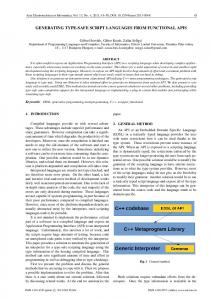
1. Introduction The aim of the ongoing research is to shift from manual design of disposable geometries to CAD automation by introducing high-level generic geometry templates. Instead of repeatedly modelling similar instances of objects, engineers should be able to create more generic models that can represent entire classes of objects. We present new methods to eliminate non-creative geometric drawing and modelling by performing reuse on specific design features. The goal is to allow engineers to work on a higher abstraction level where the use of low-level CAD functions during the drawing and modelling phase is minimized if not fully eradicated [1]. Descriptive geometry provides insight into the structure and metric properties of spatial objects, processes, and principles. Descriptive geometry courses cover not only projection theory but also modelling techniques for curves, surfaces, and solids, thus offering insight into a broad variety of geometric shapes [2].
Content from this work may be used under the terms of the Creative Commons Attribution 3.0 licence. Any further distribution of this work must maintain attribution to the author(s) and the title of the work, journal citation and DOI. Published under licence by IOP Publishing Ltd 1
WMCAUS IOP Publishing IOP Conf. Series: Materials Science and Engineering 245 (2017) 062039 doi:10.1088/1757-899X/245/6/062039 1234567890
CAD software is used to increase designer productivity, improve design quality and communications through documentation, and create databases for manufacturing. As the CAD modelling techniques become more and more advanced, it is necessary to complete product modelling and design changes faster than ever [4]. Updating assemblies that have hundreds of sub-assemblies and parts manually in 3D modelling software is very complicated and time consuming. Undoubtedly, once a task is fully defined, computers and machines are unparalleled in executing it repeatedly with great speed and sustained accuracy. To this end, Hopgood [3] states: “computers have therefore been able to remove the tedium from many tasks that were previously performed manually”. The process referred to is also called Design Automation (DA) by various researchers. The key phrase here is that many manual tasks have been removed through DA and a natural question would be: why not remove the tedium from all manual tasks? [4]. One of the great benefits of using CAD to create technical drawings is the ability to adapt to suit our company’s processes. If we can establish a technical drawing process that we perform frequently, it can be automated. If we’ve ever had to do the same thing with CAD twice, think about how we could automate it so we never have to do it again. One of the easiest ways to automate a CAD process is to write a script [5]. In computer programming terms, a script is a program that will run with no interaction from the user. In AutoCAD [6], a script file is an ASCII text file that contains a set of command line instructions to follow, just like an actor reading from a script. AutoCAD script files always have the file extension ‘.scr’. AutoLISP [7] is the original and most popular programming language for AutoCAD. The reason for its popularity is that it is a natural extension of the program. No additional software needs to be run, and AutoLISP can run commands that Autodesk and other developers offer in the command window. The LISP code can be entered directly into the command window or loaded using '.lsp' or '.scr' files. Once a LISP program has been loaded, the built-in functions can be executed from the command window. These functions can be executed similarly to CAD commands, but it is the programmer who decides which messages to display. It is possible to use LISP code with a command macro that is activated from the CAD user interface or from a tool on a palette. Visual languages can be very useful for helping architecture students understand general programming concepts, but scripting languages are fundamental for implementing generative design systems [8]. It is possible to learn to draw with AutoCAD and to program with AutoLISP for AutoCAD using the manuals and online aids offered by both Autodesk (knowledge.autodesk.com) and other independent developer websites (lee-mac.com, afralisp.net, or cadtutor.com). Self-learning through tutorials and videos is very widespread and numerous websites are available to solve any questions we may raise using advanced search engines if we search for the terms ‘AutoCAD’ or ‘AutoLisp’ as appropriate. In the design of complex engineering products it is essential to handle cross-couplings and synergies between subsystems [9]. An emerging technique that has the potential to considerably improve the design process is multidisciplinary design optimization (MDO) [1]. MDO requires a concurrent and parametric design framework. Powerful tools in the quest for such frameworks are DA and knowledge-based engineering [9]. The required knowledge is captured and
2
WMCAUS IOP Publishing IOP Conf. Series: Materials Science and Engineering 245 (2017) 062039 doi:10.1088/1757-899X/245/6/062039 1234567890
stored as rules and facts that will finally be activated upon demand. A crucial challenge is what kind of knowledge to store in order to create generic DA structures and how to store it. In an effort to address the above challenges, this paper proposes the creation of High-Level CAD templates (HLCts) for the manipulation of geometry and High-Level Analysis templates (HLAts) for concept evaluations. 2. High-level CAD templates in non-parametric CAD AutoCAD and other compatible applications automatically create object identifiers, hidden during the drawing process, that a user usually does not know. These are necessary for the internal manipulation of the objects, but because of their extensions they are difficult to use learning descriptive geometry procedures. Through LISP variables it is possible to create geometric and object references similar to those traditionally used in descriptive geometry. These references will be very useful in the detailed description of graphic procedures. In the command window, macros, and script files, the use of CAD drawing commands can be combined with LISP commands, functions, and variables (used as geometric and object references). They are equivalent: _vpoint _r !alfa !beta
; in script files and in the command window
(command “_vpoint ” “_r” alfa beta)
; in LISP files and in script files
Notes: The comment lines are preceded by semicolons and serve to facilitate the understanding of the code. All AutoCAD commands preceded by the underscore will be executed even if the program is installed in another language. The references used in the script files or in the command window are preceded by the exclamation mark. The keyword "_rotate" and its abbreviation "_r" do not use the quotation marks in the commands but use them in the command function. LISP functions (in parentheses) can be used as arguments in CAD commands. The commands can be used in LISP using the command function. Addressing a simple design task using advanced CAD applications is not difficult. But some specific designs require the application of traditional methods of descriptive geometry. To solve them efficiently requires a detailed analysis of possible combinations. The incorporation of mathematical functions with geometrical and topological calculations is fundamental to avoid drawing step by step. This is the proposed case of HLCts with non-parametric CAD using script languages. Procedure for creating HLCts is as follows: Examples are selected from standard tasks where CAD applications do not offer solutions. It can be solved first as paper-and-pencil sketches and later with AutoCAD. The command history is extracted and summarized it in script files. To avoid unexpected errors when executing drawing commands using scripts, it is essential to disable certain drawing aids, visible in the status line, and to activate them when finished. Reference variables are created with the parametric data and the objects are drawn. We calculate the derived references that can be reused and redraw. A later analysis will allow us to process the information in a global way using variables, functions, and commands created with AutoLISP. A detailed analysis and design allows us to anticipate possible strategies to complete the design. We create the analysis functions necessary to deal with any situation. Finally, we carry out debugging to remove possible errors. We present and discuss the results of two practical examples of the workplace: 1) automation of axonometries and 2) automation of ellipses with conjugated diameters. The first example uses the bearing of the coordinate axes to determine the type of projection. The second example uses the Mannheim method.
3
WMCAUS IOP Publishing IOP Conf. Series: Materials Science and Engineering 245 (2017) 062039 doi:10.1088/1757-899X/245/6/062039 1234567890
3. Results and discussion In the automation of axonometries, we calculate the viewing direction in space from the tripod of axes on the paper and we obtain blocks with the projections.
Figure 1. LISP – Axo command
Figure 2. Axonometric projections In oblique projection, we look for an orthographic intermediate projection, where we calculate the angle alpha of the X-axis as a function of the angle of the reduced axis and the angle beta from the XY plane as a function of the coefficient k of reduction. The block of the intermediate projection is inserted with a scale EscY as a function of the coefficient of reduction. The line thickness, base point, and colour errors in the projections are corrected. This method can be applied to obtain shadows on horizontal, frontal, or profile planes.
4
WMCAUS IOP Publishing IOP Conf. Series: Materials Science and Engineering 245 (2017) 062039 doi:10.1088/1757-899X/245/6/062039 1234567890
Figure 3. LISP – Military function
Figure 4. LISP – Flat shot block properties function
Figure 5. LISP – Cavalier function
Figure 6. Lisp – Orthographic axonometric function 5
WMCAUS IOP Publishing IOP Conf. Series: Materials Science and Engineering 245 (2017) 062039 doi:10.1088/1757-899X/245/6/062039 1234567890
In the orthographic projection, we use the graphic method of the fundamental triangle or of traces for the calculation of the angles of the X-axis and XY-plane. In the automation of ellipses with conjugate diameters, we follow the Mannheim method for obtaining the principal axes, ellipse, or procedure step-by-step (as a learning tool). This method can be applied to obtain projections of revolving surfaces: cone, cylinder, sphere and toroid.
Figure 7. Lisp – Mannheim command
Figure 8. Mannheim procedure
6
WMCAUS IOP Publishing IOP Conf. Series: Materials Science and Engineering 245 (2017) 062039 doi:10.1088/1757-899X/245/6/062039 1234567890
The exposed typology of HLCts of geometry and modeling, based on ontologies, represents a great advance for the automatic generation of designs, which can be repeated with multiple parametric data. But only a concurrent and parametric design structure can determine what kind of knowledge it is necessary to store to discover generic structures of design automation and how to store it.
Figure 9. Conjugate diameters ellipse function
Figure 10. Lisp – Mannheim procedure function HLCts of geometry and modelling can be useful for: combining traditional and modern methods of design, recognition and generation of designs with geometric patterns,
7
WMCAUS IOP Publishing IOP Conf. Series: Materials Science and Engineering 245 (2017) 062039 doi:10.1088/1757-899X/245/6/062039 1234567890
serving as a platform for learning from existing designs, serving as a development platform for the creation of new templates. Only the synergy of mathematics, descriptive geometry, and CAD will enable designers to advance in the development of new derivative designs in less time and with less effort. In this sense, Stachel [2] writes that "only people with a deep knowledge of descriptive geometry will be able to make extensive use of CAD programs" and also that "the importance of mathematics continues to increase even though computers take charge of the computational work".
Conclusions If we tackle a design task with traditional procedures, the same can be done with CAD applications. The study and analysis of the tasks undertaken allow us to carry out generalization of HLCts to achieve their automation. A thorough analysis will allow us to use the HLCts in tasks not initially foreseen. This document proposes a method of automating existing procedures to produce certain designs. The proposed method is analysed with varied data in the two examples presented, allowing the following conclusions to be drawn: 1. by using automation processes, it is possible to undertake designs without effort by the user; 2. automation in the generation of designs not only saves time but also increases the quality of the results and reduces the possibility of human errors; 3. multidisciplinary optimization of design reduces the learning effort and speeds up the acquisition of graphic skills. Expert users perform the initial creation of HLCts, but their use and modification do not require advanced knowledge. Acknowledgment(s) This paper has been developed with the financing of FEDER funds under the projects TIN201340658-P and TIN2016-75850-R. References [1] Amadori, Kristian, et al. "Flexible and robust CAD models for design automation." Advanced Engineering Informatics 26.2, pp. 180–195, 2012. [2] Stachel, Hellmuth. "The status of today’s Descriptive Geometry related education (CAD/CG/DG) in Europe." Journal of Graphic Science of Japan 41. Supplement 1, pp. 15– 20, 2007. [3] Hopgood, Adrian A. “Intelligent Systems for Engineers and Scientists”, CRC Press, 2012. [4] Siddesh, S., and B. S. Suresh. "Automation of generating CAD models." Journal of Mechanical Engineering and Automation 5.3B, pp. 55–58, 2015. [5] Ambrosius, Lee. AutoCAD Platform Customization: User İnterface, AutoLISP, VBA, and Beyond, John Wiley and Sons, 2015. [6] AutoCAD [computer program]. Autodesk, 2017. [7] AutoLISP (Part of AutoCAD) [computer program]. Autodesk, 2017. [8] Celani, Gabriela, and Carlos Eduardo Verzola Vaz. "CAD scripting and visual programming languages for implementing computational design concepts: A comparison from a pedagogical point of view." International Journal of Architectural Computing 10.1, pp. 121– 137, 2012. [9] Tarkian, Mehdi. Design Automation for Multidisciplinary Optimization: A High Level CAD Template Approach, 2012.
8