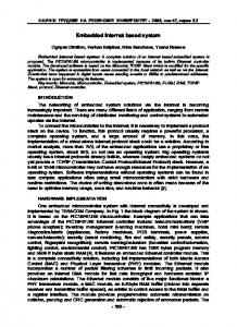
Abstract. Intelligent safety embedded systems used in cars are useful for keeping the safety of the driver and passengers. These systems must be characterized ...
Design Embedded System for Safe Car Driving based Arduino Asst. Lect. Gregor A. Aremice Al-Mustansiriya University Abstract Intelligent safety embedded systems used in cars are useful for keeping the safety of the driver and passengers. These systems must be characterized by precision and ease of use, also must be characterized to be a fairly simple and inexpensive. In this research an Arduino based ATmega328 microcontroller is used to design a system that switches (ON/OFF) car headlight bulb high beam depending on car speed in (Km/h), where car speed is measured using pulsed optical speed sensor. When car measured speed exceeds a specified threshold speed in (Km/h) then car headlight bulb high beam is switched ON after checking the (Day/Night) status using LDR photo-resistor. Keywords: Car Safety System, Embedded System, Car Headlight Bulb Control, Optical Speed sensor, Arduino
ATmega328
1
1. Introduction There are always many things to do before starting to drive a car, and most drivers almost forget one or more of these things to do before driving and start to do them after driving, then accidents happen, such things like; forgetting to use seatbelt, forgetting to set controls (choose radio station, adjust the seat, adjust heat, …etc..). Sometimes there are things must do during driving, like, obey speed limits, turn on signals to make intension to the other drivers when turning and to turn on car headlight bulb high beam when start to drive faster for example. So the need of smart safety (stand-alone) systems to be used in cars is very important. Integrated (standalone) car safety systems varies as their usages, such as, smart seatbelt system, some of these systems prevents car starting on unless the driver wear seat belt; [1] collision avoidance system, in order to minimize collision accidents modern collision avoidance systems work now using laser sensors and a special CAN controller with wireless media; [2] airbag system; collision dangerous analysis is accomplished fast to decide whether airbag to be opened or not to avoid accidents; [3] anti-lock breaking system, headlights, turn signals, etc. In this research a design of a smart stand-alone automatic switcher, for car’s high beam headlight bulb is presented. The switching operation depends on the speed of the car, i.e. the smart switcher turns the high beam headlight on, whenever the speed of car exceeds a specific threshold. This produces far vision of the road while driving fast at night, without the need to switch-on the high beam bulbs manually by the driver, leading to less possibility of accidents, which caused by short vision of road. 2. RPM and Speed Measuring Car speed measuring accomplished using speedometers. In general, two main types of speedometers are available, (electronical and mechanical) speedometers. Focusing on the electronical speedometers, they are using speed sensors which are fixed on the speed gearbox or on the crank shaft, and they consists of a toothed metal
2
disk, when car starts to move then the disk rotates and pulses are generated from a magnetic coil, and from the frequency of these pulses the speed of car is measured. In general, the term encoder is a term used with transducers that generate a coded reading of a measurement; a shaft encoder is a digital encoder that is used for measuring angular displacement and velocities, it is of two types: Incremental and Absolute. The output of the Incremental encoder is a pulsed signal that is generated when a motion is occurred. The parts that construct this encoder are a (disk) that has equally spaced and identical windows, a Light Emitted Diode (LED) for a light beam generation and a photosensor that picks the light generated from the LED. [4]
Figure 1: Schematic Representation of an Optical Encoder There are two methods for determining velocities by the incremental encoder, pulse counting (frequency measurement) which is accurate for fast moving devices like motors and turbines with thousands of revolutions/minute: [5] (
⁄
) (
⁄
)
(
... (1)
)
pulse timing which is accurate for slowly moving devices like shafts with less than 10 revolutions/minute. ... (2) Speed calculated from RPM depends on car wheel radius, so: (
⁄ )
(
3
)
... (3)
3. Proposed System The proposed system in this paper is used to control car headlight bulb high beam depending on three parameters, the first parameter is related with car speed which is measured in (Km/h), and the second parameter is related with (day/night) status and the third parameter is related with the status of the high beam case. Figure (2) shows a representation to the structure of the proposed system with the following main parts: 1. 2. 3. 4.
Arduino UNO based (ATmega328 microcontroller) Arduino Relay Module FC-03 infrared pulse counter LDR (photocell resistor)
Figure 2: the structure of the proposed system When car engine starts ON, the system is started ON too. Arduino gets data from the FC-03 sensor when car starts to move from standstill, and gets data continuously from the LDR resistor, and also reads continuously the available current flow from the direct connection that indicates the status of the high beam on the headlight bulb. The system operates according to the following algorithm:
4
if Car_Speed in (Km/h) > Specific (Threshold) Car_Speed in (Km/h) and if Day/Night_Status = Night and if HeadLight Bulb High Beam = OFF then Set HeadLight Bulb High Beam to ON The FC-03 infrared sensor is connected to Arduino through (PIN 2), when car wheel starts a rotation, pulses return to Arduino in order to measure car speed in (Km/h). The LDR returns the case of Day/Night status to Arduino at (PIN A0). A Direct connection from relay port (NO) to Arduino (PIN 10) is available to sense current flow that indicates the status of headlight bulb high beam case whether it was ON or OFF.
When
Car_Speed
exceeds
the Threshold
Car_Speed and
Day/Night_Status indicates to “Night” and the HeadLight Bulb High Beam is “OFF” then a decision is made to switch ON the HeadLight Bulb High Beam automatically. Figure (3) shows the flowchart of the proposed system:
Figure 3: the proposed system flowchart
5
4. Implementation of the Represented System A prototype of incremental encoder and headlight bulb is used to implement and test the system operation. Figure (4) shows the implemented system parts:
(a)
(b)
(c)
(d)
(e)
(f)
(g)
(h)
(i)
6
(j)
Figure 4: Implementation of the Represented System (a,b,c,d,e,f,g,h,i,j)
In Figure (4-a) shows the FC-03 sensor and a disk representing the incremental encoder prototype (with the case of a standstill car), Figures (4-b), (4-c) and (4-d) show the Arduino UNO, the relay module and the LDR photo-resistor respectively, Figure (4-e) shows a prototype to the car headlight bulb (only low beam is ON), Figure (4-f) shows the a representation of the rotated disk (with the case of moving car). The used Threshold Car_Speed in this work is (60 km/h), now, referring to the representation above and referring to Arduino IDE software serial monitor, when car start to move and its speed exceeds (60 Km/h) but the Day/Night_Status indicates “day” case then HeadLight Bulb High Beam remains “OFF”, Figure (4-g). When Car_Speed doesn’t exceed (60 Km/h) and the Day/Night_Status indicates “night” case then HeadLight Bulb High Beam remains “OFF”, Figure (4-h). When Car_Speed exceeds (60 Km/h) and the Day/Night_Status indicates “night” case then HeadLight Bulb High Beam status changes to “ON”, as shown in Figures (4-i) and (4-j).
7
5. Conclusion A simple and low cost design of a smart automatic switcher is accomplished to switch (ON/OFF) automatically the high beam of car’s headlight bulb depending on car’s speed utilizing optical speed sensor. This smart system operates independently from the origin manually system of switching (ON/OFF) the high beam of car’s headlight bulb, but sometimes when the driver is busy and forget to switch the high beam of the headlight and when he reaches by car to a high speeds at night driving then the automatic system will work.
Referencecs [1] S. Anil Babu, Sumathi Ayyalusamy, Rejin Ranjit Singh, Sreejin Dharmarijan, Jason James, Mohamed Anas, “ Development of Helmet Detection System & Smart Seat Belt”, IOSR Journal of Electronics and Communication Engineering (IOSR-JECE), Vol.10, No.4, 2015. [2] S.Ramesh, Ravi Ranjan, Ranjeet Mukherjee, Swarnali Chaudhuri, “ Vehicle Collision Avoidance System Using Wireless Sensor Networks”, International Journal of Soft Computing and Engineering (IJSCE), Vol.2, No.5, 2012. [3] Aini Hussain, M A Hannan, Azah Mohamed, Hilmi Sanusi, Burhanuddin Yeop Majlis, “Decision Algorithm for Smart Airbag Deployment Safety Issues”, International Journal of Computer, Electrical, Automation, Control and Information Engineering, Vol.2, No.3, 2008. [4] Hyungsuck Cho,” Opto-Mechatronic Systems Handbook: Techniques and Applications”, CRC Press, 2003 [5] OPTO 22,”RPM Measurement Techniques”,Technical Note 1784,pp.1
8