IEEE TRANSACTIONS ON CIRCUITS AND SYSTEMS—II: ANALOG AND DIGITAL SIGNAL PROCESSING, VOL. 47, NO. 11, NOVEMBER 2000
1279
Design-for-Testability Techniques for Detecting Delay Faults in CMOS/BiCMOS Logic Families Kaamran Raahemifar, Member, IEEE, and Majid Ahmadi, Senior Member, IEEE
Abstract—The delay fault testing in logic circuits is studied. It is shown that by detecting delayed time response in a transistor circuit, two types of faults are detected: 1) faults which cause delayed transitions at the output node due to some open defects and 2) faults which cause an intermediate voltage level at the output node. A test circuit is presented which enables the concurrent detection of delay faults. The proposed delay fault testing circuit does not substantially degrade the speed of the circuit under test (CUT). Simulation results show that this technique fits any design style. Index Terms—Concurrent testing, delay fault and stuck open fault testing, design for testability, fully testable CMOS circuit, VLSI testing.
I. INTRODUCTION EFECTS in both CMOS and BiCMOS technologies include shorts between the connections,1 open connections,2 and transistor stuck-on.3 CMOS circuits can also fail due to circuit degradation (e.g., threshold voltage variations). It was reported in [12] that in a conventional BiCMOS NAND gate, each injected defect may result in one or more logical fault(s), as explained below. Defects may cause a parametric fault by altering either of the delay time, quiescent supply current, or output voltage magnitude. Some defects degrade the output voltage, causing an intermediate voltage level or a soft logic level (an output which lies in the correct logic level, but has a degraded voltage). The result is a reduced noise margin. The other class is that of functional faults, which includes stuck-open (the output becomes floating and the circuit shows a sequential behavior), truth-table (the output takes a wrong logic level for certain input combinations), and stuck-at faults. It is also stated in [12] that the set of “delay faults,” faults” is an adequate fault set “stuck-open faults,” and “ to detect faults (stuck-at faults included) in a CMOS circuit. Short defects and their effects on BiCMOS circuits were studied in [13], and a DFT technique was proposed for facilitating the detection of these defects. This paper deals with delay
D
Manuscript received November 1999; revised July 2000. This work was supported by a Research Grant from the Natural Sciences and Engineering Research Council of Canada. This paper was recommended by Associate Editor E. Friedman. K. Raahemifar is with the Electrical and Computer Engineering Department, Ryerson Polytechnic University, Toronto, ON, M5B 2K3, Canada, (e-mail:
[email protected]). M. Ahmadi is with the Electrical Engineering Department, University of Windsor, Windsor, ON, N9B 3P4, Canada (e-mail:
[email protected]). Publisher Item Identifier S 1057-7130(00)09945-6. 1Shorts
are modeled as a small resistor between the two nodes. circuits are modeled as a large resistor inserted between the affected node and the node to which it would normally have been connected. 3A transistor stuck-on is a transistor that is always in the conducting mode. 2Open
and stuck-open faults, and presents a novel DFT technique for detecting them. We show that the modified version of this technique is capable of detecting short defects too. Delay-fault testing is quite important in CMOS/BiCMOS logic families, because it is the only means of detecting certain manufacturing defects. The proposed DFT approach for delay faults allows concurrent testing and can easily be compatible with any design style. It is also capable of detecting faults which cause intermediate voltage level at the output of a given circuit. The faults in the added testing circuitry are either detectable or have no effect on the normal operation of the circuit. This circuit is applicable to any given block, and is efficient in terms of area and speed. We distinguish concurrent and on-line testing techniques using the following definitions. Definition 1: The previous or current value of the output need not be known for detecting the fault in a concurrent testing technique. However, the circuit may or may not operate in normal mode while testing is performed. Definition 2: We call a testing technique on-line if the testing is performed while the circuit is in normal mode of operation. Occasionally, the faulty node should be excited by a test vector, and/or its faulty behavior should be propagated to the primary output. To attain this goal, one or two test vectors are devised using test generation algorithms, and applied to the primary inputs of the circuit. The testing is achieved if it begins after the normal operation of the circuit is halted. Such a testing technique is neither concurrent nor on-line. On the other hand, there are testing techniques [1]–[3] which operate using the physical characteristics of the faulty node, and do not rely on exciting (or propagating) the fault. However, these techniques may detect the fault if the circuit is not functioning in normal mode. This class of testing technique is considered to be concurrent in this paper. If the faults in the circuit are detected as they occur in normal mode of operation, the testing technique is on-line. The rest of this paper is organized as follows: Section II reviews delay faults and the importance of detecting them. It also discusses the drawbacks of the techniques proposed in [1]–[3] for detecting this fault. In Section III, we present a DFT technique which is free from similar shortcomings. Stuck-open and intermediate-output faults are the subject of Section IV. Fully testable CMOS designs are discussed in Section V. HSPICE simulation results are given in Section VI. Generation of controlling signals for asynchronous circuits are discussed in Section VII. Their faulty behaviors are explained in Section VIII. The test results for medium size circuits are reported in Section IX. Conclusions are provided in Section X.
1057–7130/00$10.00 © 2000 IEEE
1280
IEEE TRANSACTIONS ON CIRCUITS AND SYSTEMS—II: ANALOG AND DIGITAL SIGNAL PROCESSING, VOL. 47, NO. 11, NOVEMBER 2000
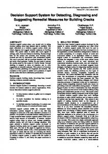
II. DELAY FAULTS IN BiCMOS CIRCUITS It was mentioned in [13] that some defects do not change the functional behavior of the circuit, and only increase the propagation delay of the circuit from the specified limit. The result is a delay fault, which may manifest itself as a “slow to rise” or a “slow to fall” transition. It is important in high-speed applications to detect delay faults to ensure that the circuits work as intended. Also, it has been shown [6] that even those delay faults which are not important in a particular application may cause functional problems and create logical faults in BiCMOS circuits. Thus, delay-fault testing is of great importance. The simplest form of delay-fault testing is to apply pseudo-random patterns to the circuit under test (CUT) at a desired speed. This method requires very long test lengths to achieve an acceptable fault coverage [16]. The other drawback of this method is that tests can be invalidated by delays in other parts of the circuit. A test that detects a delay fault of a certain size does not necessarily detect faults that have longer or shorter delays [3]. The analyses described in [12] supported the results reported in the literature [5], [6], [8]–[10], [15] that most open defects manifest themselves as delay faults. However, a few short defects also result in a delay fault. These analyses further revealed that as the redundancy of BiCMOS structures increases, fewer open defects can be detected by stuck-open tests. In order to detect these defects, delay-fault testing must be performed. Delay faults appear as one of the seven alternatives shown in Fig. 1. Graph a shows a fault-free output signal, in a high-to-low transition. The waveform in graph b is slow-to-fall. Although it starts its transition as early as the fault-free signal, it requires much more time to reach its final value. The waveform depicted in graph c does its high-to-low transition as fast as the fault-free before it starts the signal. However, there is a time delay transition. The waveforms in graphs a–d show high-to-low transitions. Similar malfunctionings can occur in a low-to-high transition. The high-to-low transition in case d happens well after and is too late to be detected by the current phase of delay-fault testing given by the sampling clock. The sampling clock has changed its logic value and the testing phase is terminated already. The waveform in graph e shows an intermediate voltage value which cannot be verified as either “1” or “0”. While graph f shows stuck-at 1, graph g shows stuck-at 0. The waveforms in graphs e, f, and g can be interpreted as a delay fault with infinite delay. Although test pattern generation for stuck-at faults is different than that of delay faults but similar in many ways, graphs e, f, and g suggest that these faults can be detected by the test patterns employed for delay-fault detection. We show that a delay-fault testing technique that detects fault type b, may not detect fault type c. There are cases where the delay-fault technique detects types b and c, but not e, f, or g. In either of the cases b and c as depicted in Fig. 1, the faulty output finally reaches the correct value. However, if the output is observed at an appropriate time (at the maximum acceptable normal delay), the fault can be detected. To detect a delay fault, a two-pattern test is applied to create and propagate signal transitions along the path to be tested. The first input vector initializes the output to a known state. The circuit is allowed to stabilize
Fig. 1. Different appearances of delay fault.
under this input vector. At time , the second input vector is applied such that the output changes to the opposite logical level in the fault-free circuit. The output is sampled at time , where corresponds to the maximum acceptable delay for the fault-free operation. The clock frequency is proportional to . If the output does not reach the opposite the inverse of logical level in the presence of any of the two types of faults, then the fault can be detected. Two-pattern tests have been widely used for testing stuck-open and delay faults in logic circuits. However, they can be invalidated by circuit delays, hazards, and timing skews [4], [14]. As a result, there have been some efforts to eliminate the need for them. One such effort is the design-for-testability technique proposed in [2], [3] for detecting delay faults in CMOS circuits. The authors discuss the importance of observing the output waveform between the samples, instead of only latching the output at the sampling time. Fig. 2 shows how a delay test, based on latching the output at specific sampling times can be invalidated due to a dynamic hazard. Since there is significant information in the output waveform between samples, they propose to perform delay testing by applying test patterns and sampling the output in the conventional manner, together with a circuit that monitors the output waveform between samples. In order to observe any changes after the sampling time, they have proposed the DFT technique, shown in Fig. 3. This circuit uses the transient switching current in CMOS inverters to detect signal changes. While is low, the bus is kept by the precharging transistor, so the inverters operate at normally. changes to logic high, when all the nodes of interest in the CUT (circuit under test) are supposed to have stabilized in the fault-free case. Once is high, the bus is left floating. If
RAAHEMIFAR AND AHMADI: DESIGN-FOR-TESTABILITY TECHNIQUES FOR DETECTING DELAY FAULTS
1281
Fig. 2. Delay-test invalidation by dynamic hazard.
out does not change, the corresponding inverter will draw negligible static current and the bus will remain high. If any out changes, the transient current while the inverter changes state will partially discharge the bus, which can be detected with a sense amplifier. This technique suffers from the following shortcoming. 1) The bus node does not go all the way down to 0 V, because pMOS transistors are imperfect switches when passing a zero. This is due to the fact that a pMOS transistor with gate node at voltage 0, begins to turn off when the output (threshold voltage). Similarly, nMOS voltage reaches transistors are imperfect switches when passing a ONE, ceases conbecause an nMOS transistor with gate at . Therefore, the ducting when its output reaches . Our simulations show output does not go lower than that the bus node does not discharge below 1.5 V. This, reduces the noise margin and may cause difficulties in fault detection. Fig. 4 shows another DFT technique proposed in [1]. Here, and . The rising there are two controlling signals, and the falling transition on signals antransition on for the circuit nounce the end of the valid reading time is generated through an intermediate logic circuit. signal . is “1” if does not show a transition after . If changes after the transition on and due to a delay fault, the to zero and the fault is detected. extra logic circuit will set The method has several drawbacks. 1) The authors have pointed out that their delay-fault test circuit fails to detect an existing fault if skews happen in the and . Such behavior is expected either transitions of due to the presence of clock skews, or the delay associated . The authors with the inverter which generates have also shown that glitches at the test circuit nodes can invalidate the results. 2) The presented method also needs ratioed capacitors. 3) The method can detect one type of faults which causes a delayed transition [see Fig. 1(c)]. Type “b” is not detected by this method. III. PROPOSED DFT TECHNIQUE DETECTION
FOR
DELAY-FAULT
We propose a new DFT technique for detecting delay faults, which does not suffer from the shortcomings of the techniques presented in [1]–[3]. We adopt their approach of observing the output waveform between the samples instead of only latching the output at sampling time. This will ensure that our method
Fig. 3. DFT technique proposed in [3] for post-sampling analysis.
Fig. 4. [1].
(a) Delay-testing circuit. (b) Schematic timing diagram as presented in
will not be invalidated by excessive delays. However, in the proposed circuit, the generation of the error signal is not based on the current drawn during the transition. On the contrary, it is based on charging or discharging an internal node to a logic level. Like the techniques proposed in [1]–[3], we monitor any changes in logic value of the internal node. The proposed technique is graphically depicted in Fig. 5. Fig. 5 shows the initial steps we have taken to modify the proposed techniques in [1]–[3]. An improved version of this deor is posign is discussed later. Here, the control signal sitioned in the middle and the circuit signal is distributed to the uppermost pMOS and the lowest nMOS transistors. The circuit is high and is low in in Fig. 5(a) operates as follows. normal mode of operation. This would create a short path beand , and the the test circuit operates like a CMOS tween and have the same logic inverter. Regardless of what is, values, which is the inverted value of signal . The rising tranor the falling transition of marks the end of the sition of maximum delay in the fault-free circuit ( in Fig. 1). Therefore,
1282
IEEE TRANSACTIONS ON CIRCUITS AND SYSTEMS—II: ANALOG AND DIGITAL SIGNAL PROCESSING, VOL. 47, NO. 11, NOVEMBER 2000
(a)
(b)
(c)
Fig. 5. Proposed concurrent checkers for delay faults using: (a) two control signals 8 and 8 ; (b) 8 only; and (c) 8 only.
when changes to low or changes to high, all the output signals of the fault-free circuit have already stabilized to their and are turned off. At final values. At , both transistors or becomes floating, and tends this time, one of the nodes to maintain its previous value. Since there is no delayed transiand tion of the signal after time in the fault-free case, keep their previous values. In a circuit with excessive delay, however, one of the outputs will change after the expected time . As a result, the state of the or transistor will change. This will cause the logic value to change in one of the nodes or , i.e., either or will assume a value other than its will either be 01 or 10. The previous value. As a result, and is detected by an XOR difference in logic values of circuit. Fig. 5(b) and (c) operate on a similar basis. They intend to or in provide a short path between Out and either of from in test mode. None of normal mode, and disconnect or these techniques need ratioed capacitors, and glitches on would not have any effect on testing results. As an example, or changes its consider Fig. 5(a). As soon as either of normal mode logic value, the uppermost and the lowest transistors are disconnected and the circuit is ready for fault inspection. Fig. 5(b) and (c) offer less area overhead compared to that of Fig. 5(a) because they have one transistor less, and the generation of the inverted control signal value is prevented. We recommend Fig. 5(b) since nMOS transistors tend to operate faster and introduce little voltage drop while they are on. We propose test circuits for CMOS circuits which work on the same principles (see Fig. 6). We have adopted the structure in Fig. 6(b) for the rest of this paper since it introduces less area overhead, and has less loading effect on normal operation of the CMOS circuit. When input patterns in CMOS circuits are such that the output tends to become ONE, the -part is turned off, creating a high impedance between the output node and the ground. This permits the output node to take any new voltage value or keep its previous voltage level. At the same time, the -part provides
Fig. 6. Proposed concurrent checkers for delay faults using: (a) two controlling signals 8 and 8 ; (b) 8 only; and (c) using 8 only.
Fig. 7.
Proposed concurrent stuck-open detector.
a short path between the output node and charging the output capacitor to logic ONE. Similar events happen when the output tends to become ZERO. While the -part is presently off, a discharging path for the output node is provided through the
RAAHEMIFAR AND AHMADI: DESIGN-FOR-TESTABILITY TECHNIQUES FOR DETECTING DELAY FAULTS
TABLE I EFFECTS OF THE DFT TECHNIQUE FOR DELAY/STUCK-OPEN FAULT DETECTION ON THE CIRCUIT PARAMETERS
1283
hand, turns on and discharges to ZERO. This provides a which is detected difference in the logic values of Out and by an XOR and a delay fault is announced. A stuck-open fault can be interpreted as a delay fault with infinite delay. This suggests that it can be detected by the means employed for delay-fault detection. However, the concurrent delay checker presented in this section is not capable of detecting stuck-open faults, because it responds to the delayed transition of the signal under test. If the signal does not make any transition for a test vector (which is the case for stuck-open faults), it will remain undetected with this method. Therefore, it is necessary to devise a DFT technique for detecting stuck-open faults. The following sections demonstrate that the technique mentioned above, if modified, is capable of detecting stuck-open, fault. We prove that stuck-on, inconclusive voltages, and the proposed technique also provides single and multiple fault detection at the expense of a little area overhead. IV. DETECTING STUCK-OPEN FAULTS The DFT technique presented in [13] results in a high coverage for short defects and bridging faults in BiCMOS circuits. Its inability to detect most open defects is compensated by the concurrent BIST technique presented in Section III for delayfault detection. While the first technique targets the short defects, the second technique attempts to detect the open defects which normally result in delay faults in CMOS/BiCMOS circuits. The stuck-open fault occurs when the output becomes or GND via a conducting floating (not connected to either path). Therefore, the output remains at its previous value. So, for an input vector that excites a stuck-open fault, the faulty output is different from the fault-free output. Thus, the standard method for detecting stuck-open faults is to apply two-pattern test vectors and observe the output. However, generation of robust two-pattern tests (which are not invalidated by timing skews) is a complex process. The requirement of large CPU times makes the test generation very costly. It is also possible that a combinational circuit may not have any two-pattern robust sequence [14].
Fig. 8.
Proposed fully testable CMOS design.
A. Proposed DFT Technique for Stuck-Open Fault Detection -part to the ground. Although both parts are on for a short time while the output is in transition, it should not last long for a fault-free circuit. We will investigate the performance of the circuit shown in Fig. 6(b) in Section V, where we design a fully testable CMOS design. Let us illustrate the circuit operation for delay-fault testing using an example. , the voltages at nodes Out and Let us assume that at are at and is high. We further assume that the inputs are supposed to fall [see are applied long ago so that Out and changes to ZERO, Fig. 1(c)] in fault-free circuit at or before i.e., the -part is off and the -part is on at . Since there is in the no delayed transition of the output signal after time will keep their previous values. The fault-free case, Out and -part turns off at if a delay fault exists. At this time, node Out becomes floating, and tends to maintain its previous value, which is ONE in this example. The -part, on the other
The basic idea of the proposed technique is to apply a test signal to the output such that it undergoes a consequent transition in case of a stuck-open fault. The concept of applying an external signal to the output is an adaptation of the design method presented in [4], [8], [11]. Similarly, our proposed circuit does not need two-pattern test vectors. Therefore, it cannot be invalidated by timing skews, delays, glitches, or charge sharing among the internal nodes. Fig. 7 shows the concurrent circuit for stuck-open fault detection. It consists of two nMOS transisand , which are used for generating a transition on an tors output affected by a stuck-open fault. The operation of the cirhave equal logic values cuit is based on the fact that Out and in the fault-free circuit. These outputs will not be affected if they are momentarily connected to a weak signal. However, if the circuit has a stuck-open fault, both the -part and the -part show high-impedance states if the input vector excites the fault and
1284
Fig. 9.
IEEE TRANSACTIONS ON CIRCUITS AND SYSTEMS—II: ANALOG AND DIGITAL SIGNAL PROCESSING, VOL. 47, NO. 11, NOVEMBER 2000
Alternative solutions for the current sensor using: (a) a NOR gate and (b) one inverter.
TABLE II FAULTY AND FAULT-FREE BEHAVIORS OF CMOS CIRCUITS AT
t >t
propagates it to the output. Therefore, a weak signal can overand , drive the output. These weak signals are applied via which are controlled by the sampling clock, . and should be chosen such that the The dimension of on-resistance of these transistors are considerably higher than that of the pull-up or that of the pull-down network. In general, minimum-size transistors are sufficient for this purpose. does not charge to full when is high because an nMOS transistor does not transfer ONE efficiently. Although it is possible to avoid this performance degradation by using a pMOS transistor instead of nMOS, we do not recommend it. Our simulation results shown in Table I confirms that the voltage is not substantial and does not create any degradation in major problem in the operation of the circuit. If a pMOS transistor is used instead of the nMOS transistor, the complementary will be required. However, this is the same as . signal is high and is low; therefore, the In normal operation, main output is not affected by the test circuit. In test mode,
falls to ZERO and turns off . Then, goes to high value and transistors. A floating Out and turns on both the will change to ZERO (ONE). There are two scenarios in are both ONE, the -part the fault-free circuits. If Out and floating. will charge to high is off. This will leave logic value. At the same time, the -part is on. This provides a . Although is on, it cannot short path between Out and overdrive Out to ZERO since its on-resistance is much higher will tend to be that that of the -part. Therefore, both Out and high in the fault-free circuit. If there is a stuck-open fault which is excited by the input patterns, then both pull-up and pull-down networks are off, showing high impedance between their two will drive to ONE and terminals. In this situation, will drive Out to ZERO. Therefore, the fault is detected using were a logic gate. Similar behavior is explained if Out and originally ZERO’s. This analysis also suggests that the output value need not be known. This eliminates the requirement of the test-pattern generation procedure. For each input signal applied to the circuit in normal mode, the circuit will switch to test mode after the output has had enough time to stabilize in the fault-free case, and any occurrences of stuck-open faults will be detected. V. FULLY TESTABLE CMOS DESIGNS In this section, we further improve our test circuit to provide a fully testable CMOS design. Table II summarizes all possible if the faulty and fault-free functional behaviors of Out and and have no efstructure of Fig. 7 is used. Transistors fect on normal operation of the fault-free circuit regardless of is high or low. Therefore, the controlling signal whether may have any logic value at any time. However, to minimize
RAAHEMIFAR AND AHMADI: DESIGN-FOR-TESTABILITY TECHNIQUES FOR DETECTING DELAY FAULTS
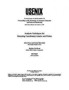
Fig. 10. Delay-fault detection using the concurrent checker. (a) Inputs. (b) Sampling clock. (c) Output and delay signal for the fault-free circuit. (d) Output and delay signal for the circuit with beq defect. “T ” assumes a low voltage level for the delayed signal.
the power dissipation, we have chosen to be low when is high. This will further facilitate the use of on-line test must be low circuit proposed in [13]. On the other hand, so that for for delay-fault testing. We can choose fault testing. We can generate this signal stuck-open and through an odd number of inverters to create a time gap long enough for the purpose of the delay-fault testing. We have discussed the behavior of the test circuit proposed in Fig. 7 at the presence of delay and stuck-open faults in Sections III and IV-A. This test circuit is also capable of detecting faults which may not be detectable through supply lines. Only one of the -part or the -part is on and the other part is off in the fault-free circuit. However, both parts tend to create a short fault, path between their two terminals in the case of an , and the -part tends i.e., the -part tends to charge Out to to ZERO. The fault is announced at the to discharge . combination Out Our fully testable CMOS design is schematically illustrated and . Similarly, signal in Fig. 8. Signal Out is connected to is connected to and . Fig. 8 shows only two set of and Out , while in a complex sequensignals Out representing the states tial circuit any set of outputs Out of the primary outputs of each CMOS block can be tested by is used to create a the above circuit. One nMOS transistor
1285
Fig. 11. Detecting delay fault (type “c”) using the concurrent checker. (a) Sampling clock. (b) Output and delay signal for the fault-free circuit. (c) Output and delay signal for the faulty circuit. “T ” assumes a low level for the delayed signal.
short path between and the actual ground, and to reset the current sensor during the normal operation. The current sensor, which is a combination of two inverters as explained in [13], is employed for generating the error signal. One transistor and one current sensor are used to serve many CMOS blocks for testing purposes. The test circuit as shown in Fig. 8 does not require the complement of any of the output signals. is high and is low in The circuit operates as follows. is on and is initialized to ZERO. normal mode. switches to low in test mode after the output signal has had enough time to stabilize. If the circuit is fault-free, Out and have the same logic value, and they tend to preserve it. is not on concurrently with . The leakage current is negligible, and the output of the current sensor is high. At the will have opposing logic presence of any fault, Out and and values. This, in turn, will provide a short path between through either or . The excessive current is, then, detected by the current sensor, and the error signal from actual becomes low. This will, in turn, disconnect ground preventing excessive power dissipation. Alternative solutions are presented in Fig. 9. The current sensor is replaced in Fig. 9(a) by a CMOS NOR gate. This will increase area overhead by almost 100% as the NOR gate is used
1286
IEEE TRANSACTIONS ON CIRCUITS AND SYSTEMS—II: ANALOG AND DIGITAL SIGNAL PROCESSING, VOL. 47, NO. 11, NOVEMBER 2000
the fault-free output (graph c) is allowed to have its changes, and becomes low after the maximum acceptable delay. For the fault-free output, the signal constantly remains high, because there is no excessive current. A delayed output (graph “d”), howhas become low. ever, makes all or part of its transition after As a result, the signal assumes a low level, and the delay fault is detected, as depicted in graph d. As depicted in Fig. 1, there are different types of delay faults. The delay fault shown in Fig. 10(d) is from type “b” in Fig. 1. In order to observe a delay fault of type “c”, the inputs of a conventional BiCMOS NAND gate were tied together to form an inverter, and five such inverters were cascaded immediately after one conventional BiCMOS NAND gate. The last inverter was augmented with the proposed DFT circuitry. A defect was introduced in one of the gates to create a delay fault. Fig. 11 shows the results of a simulation. As graph c shows, this type of delay fault is also detectable by the proposed DFT technique. We repeated the simulations for other families (BiNMOS, full-swing BiCMOS, and CMOS NAND gates). Simulations show that the proposed concurrent delay checker circuit is applicable to all mentioned families, and is capable of detecting all the delay faults. B. Stuck-Open Faults
Fig. 12. Stuck-open fault detection using the proposed BIST technique. (a) Inputs. (b) Control signal. (c) Output and error signal in the fault-free case. (d) Output and error signal for a stuck-open fault.
for each CMOS stage separately, or a multiple input NOR gate is used. Favalli’s technique [1] is adopted in Fig. 9(b). This, however, suffers from the setbacks outlined earlier. Table III summarizes the operation of the test circuit for . An intermediate output is produced when both pull-up and pull-down networks conduct, and neither can overdrive the other. As a result, the output lies in a region close to (but outside) the two defined logic levels. In this faulty case, both and are conducting. This would sets of produce excessive current which is detected by the current and sensor. The fault is detected regardless of whether would overdrive the output or not. This implies that the proposed circuit can be used for detecting the defects which cause an intermediate output. VI. EVALUATION A. Delay-Fault Testing In order to evaluate the capability of the circuit in detecting delay faults, we used a conventional BiCMOS NAND gate as the CUT. HSPICE simulations were done for all defects which cause a delay fault. Fig. 10 shows the performance of the delayfault tester for the fault-free operation, as well as for (base-emitter short in transistor ) defect. This defect, as described in [13], results in a slow-to-rise output. The fault is excited by any input pattern which causes a low-to-high output and . The sampling transition. Graph a shows the inputs is shown in graph b. It is high for all the period when clock
In order to evaluate the performance of the proposed scheme for detecting stuck-open faults, a conventional BiCMOS NAND gate is augmented with the mentioned structure. For each possible single defect (three shorts and three opens for each transistor), simulation was performed and the error signal was monitored. Fig. 12 shows the result of HSPICE simulation for an defect (source of is open). The fault-free output changes from low to high when change from 11 to 01. The error signal remains high for all input vectors. The faulty output, however, assumes a high-impedance state and stays at its previous value or accepts new logic value. As a result, the fault is detected as shown in graph d of Fig. 12. All stuck-open and inconclusive voltage values are detectable by this method. Similar simulations were performed for other families (BiNMOS, full-rail BiCMOS, CMOS). The simulations showed that all the stuck-open and intermediate output faults are detectable by the proposed technique. The results obtained from simulations can be generalized by the following theorem: Theorem 1: By augmenting a CMOS/BiCMOS gate as shown in Fig. 8, any single or multiple fault in the functional part can be detected concurrently if the test circuit is not faulty. The error signal is not invalidated by timing skews/delays, glitches, or charge redistribution. Proof: In Section VI, it was shown that the test circuit, shown in Figs. 5 or 6, has no effect on logic values of Out and if the circuit is fault-free. This would allow excitation of the fault in the next stage CMOS blocks through the primary inputs. It was also shown that any single fault in the functional part is detectable. Similarly, if a multiple fault exists within one CMOS block, its faulty behavior is detected through the test circuit, or the fault is announced undetectable due to redundancy. There are two possible connections of CMOS blocks. They are either connected serially, or they operate in parallel. In the case
RAAHEMIFAR AND AHMADI: DESIGN-FOR-TESTABILITY TECHNIQUES FOR DETECTING DELAY FAULTS
1287
TABLE III FAULTY AND FAULT-FREE BEHAVIORS OF CMOS CIRCUITS AT
Fig. 13. Availability of controlling signals in asynchronous circuits in: (a) two-phase protocol; (b) four-phase protocols; and (c) in micropipelines.
of serial connection, the first faulty CMOS block would switch are the error signal. At the same time, the values of Out and changed due to the fault, see Fig. 8. Whether this combination excites the fault in the next CMOS block is not imof Out portant since the fault is already detected. In the case of parallel connection of two CMOS block, the multiple fault is detected by both of the test circuits connected to them. The previous or current value of the outputs need not be known for detecting the fault. A fault is announced if the is ZERO. Hence, one does not need output changes while to set the circuit output to ONE or ZERO by applying input patterns generated by an ATGP. This eliminates the need for the generation of test vectors in CMOS structures. According to our definition, the testing is performed concurrently. goes to ZERO after all the internal signals are norSince mally stabilized, no glitch should appear at the output. However, if some signals experience excessive delay faults, they may ). This create a glitch at the output during testing (while glitch may change the output momentarily, and a delay fault or stuck-open fault is announced. The outputs will change at the presence of other types of faults as well. The circuit is announced fault-free if, and only if, the outputs have equal logic values. QED. It should be noted that an open defect in any of the additional , or of Fig. 8 may or may not transistors be detected in this design. They may also invalidate our test results. It can be shown that such a defect does not affect the normal circuit operation. The short defects in the test circuit, however, are detectable.
t >t
Applying the proposed technique has the following effects on the normal behavior of the circuit: the output voltage levels of the circuit do not change for the fault-free circuit under normal-mode of operation. Speed performance is not degraded noticeably. The power dissipation of the circuit increases because either or try to overdrive one of the outputs in the fault-free circuit. This increase is in an acceptable range % as shown in Table I. Although it may seem as if the only disadvantage of this technique, compared to the previous ones [4], [8], [11], is its area overhead, this is not the case if we compare the area overhead attributed to this technique with that of all previously proposed counterparts combined for detecting different types of faults. Our test circuit shares many transistors to perform fault detections, and the increase in testability is quite significant. Table I shows the relative amounts of the mentioned overheads for two conventional BiCMOS circuits. The first is a twoinput NAND gate. The second is a ring-oscillator, consisting of eleven cascaded NAND gates. The last NAND gate in the ring-oscillator is augmented by the circuit shown in Fig. 8. It can be seen that the change in the output voltage levels in the normal mode is quite insignificant. Since the test circuit tries to drive the output to the opposite level, the output will deteriorate. The area increase for the simple NAND gate is not in an acceptable range, but it should be noted that for a circuit which is more complex than a simple NAND gate, this overhead decreases significantly. Table I shows that there is a very small penalty associated with the proposed technique, especially as the complexity of the CUT increases. However, the fault coverage obtained is quite significant.
VII. GENERATION OF and/or in the proposed checker can be created in synchronous circuits from the master clock with a simple circuit. For asynchronous circuits, on the other hand, it is generated using the handshaking signals, which control the maximum limit for acceptable delay as well. Fig. 13(a) provides the controlling signals based on two-phase protocol. Fig. 13(b), on and for four-phase protocols. the other hand, replaces in Fig. 13(c) is the acknowledge signal in stage of the is the the request signal in micropipeline, whereas . stage
1288
IEEE TRANSACTIONS ON CIRCUITS AND SYSTEMS—II: ANALOG AND DIGITAL SIGNAL PROCESSING, VOL. 47, NO. 11, NOVEMBER 2000
TABLE IV FAULT DETECTION COMPARISON FOR FOUR MSI STRUCTURES
TABLE V FAULT DETECTION COMPARISON FOR FOUR MSI STRUCTURES
VIII. FAULTS ON
AND
Either or can be faulty. The following faulty behaviors have been studied. and are stuck-at zero, transistors , 1) If both in Fig. 8 are off. The -part is separated from and the -part even though the circuit under test is fault-free. in Fig. 8 will have no effect on each other. Out and and will discharge Therefore, Out will charge to to GND at some point of time. Since their logic values are different, the remaining parts of the test circuit would detect the fault. stuck-at zero is detectable when we turn off 2) The fault . The same situation as described by item #1 would happen. is stuck-at one and is stuck-at zero, and 3) If are on while is off. When the -part is active, there and the ground. This causes is a short path between an increase in the static current which is provided by the power supply. Similar situation happens when the -part is active. This fault, therefore, is detectable through fault testing discussed in [13]. is stuck-at one, but is fault-free, the fault is de4) If to tectable as previous item describes when we set zero. and are stuck-at one, the fault is detected 5) If both fault. as an is always on if is stuck-at one. This fault 6) Transistor is not detectable. The time accuracy of the sensing circuit and its sensitivity and have been to possible hazards in the transitions of studied by means of SPICE simulations. There are a number of scenarios as described next. 1) If the hazards (static or dynamic) happen after the circuit under test is stabilized, the test circuit works as intended and the faults in the circuit under test would be detected. 2) If the hazards happen before the circuit under test is stabilized, changes at the circuit output would be detected by the test circuit and the presence of fault(s) would be known. and/or have delay faults. Similar arguments are valid if Hazards in the circuit outputs would also be detected in a similar and change states, fashion. (If hazards on occur before the circuit is considered fault-free. Such hazards would be harmless to the functionality of the circuit under test. If hazards on
occur after and change states, the hazards would be detected by the test circuit. Note that we consider one fault at a time in this study.)
IX. MEDIUM-SIZE LOGIC CIRCUITS Published papers on DFT techniques for testing delay faults and stuck-open faults include description of functional behavior of the test circuit. In this paper, we have described our test circuit in detail and we have made comparisons based on the functionality of our test circuit with those available techniques. No fault-simulation comparison is made since there are no benchmark circuits for the purpose of delay fault and stuck-open fault testing. Neither are there transistor sizes available in the literature to make a comparison based on experimental results possible. Injecting delay faults on a fabricated chip and testing the chip for delay fault using DFT techniques is not helpful since each injection requires one chip being fabricated. This is not practical, and for this reason, there is no fault coverage reported in the literature today on this basis. Obtaining fault coverage using delay-fault injection on a circuit at the simulation level is also difficult. This means that a faulty circuit should be simulated using SPICE. The fault coverage is obtained after simulation is performed for each delay fault. This is tedious as it has to be done manually. For this reason, there is no fault coverage reported in the literature for delay-fault testing using DFT testing techniques. To the best knowledge of the author, DFT fault coverage for delay faults has been reported in this paper for the first time, where we attach the test circuit, simulate the circuit under test with the test circuit at the transistor level, and report the results. We have selected three circuits for fault simulation which satisfy the following conditions. 1) Medium Size Circuits: Since HSPICE simulation should be carried out for each line stuck-at fault which causes increased delay, we have selected medium size circuits. 2) Modularity: In order to simplify data entry for HSPICE, we have used modular designs. Such designs are easily duplicated in HSPICE entry file giving us an opportunity to increase the size of the circuit as we wish. This will allow us to observe relationships between test circuit and circuit under test in terms of area overhead and fault coverage.
RAAHEMIFAR AND AHMADI: DESIGN-FOR-TESTABILITY TECHNIQUES FOR DETECTING DELAY FAULTS
3) Input Criterion: We have proposed delay-fault testing technique which is concurrent, and there is no need for ATPG’s. Since we have simulated faulty machines for each input combination to test the design exhaustively, we have selected designs which have only a few inputs. We have selected an 8-bit parallel binary adder [7], 8-bit multiplier [7], and the ALU 74 181. 1) The final stage of the adder and multiplier circuits gen. The longest path delay is from erate the final carry the primary inputs to . This stage has been augmented using our test circuit for delay-fault testing. 2) The critical path in a decoder is relatively small compared to other samples we considered. We have considered the Carry Generate [7] (CG) circuit for an 8-bit carry-lookahead adder [7]. The circuit function is described using the following equations:
where
and
Only one test circuit is used at the output of CG circuit. 3) The test circuit is added to only one output of the ALU 74181. and are removed from the test circuit 4) Transistors is applied. during delay-fault testing, and only 5) The maximum delay of the critical path has been considsignal. We assume that ered to estimate transitions on arrives as soon as the fault-free outputs transition on are stabilized in the worst-case scenario. is observed. 6) Only The simulation has been carried out as the following steps describe. 1) The logic designs have been changed to include only 2-input NAND gates and inverters. 2) Gate-level designs have been transformed to transistorlevel designs using CMOS NAND gates and CMOS inverters. nMOS and pMOS transistor sizes are the same as the ones we considered in this Chapter. 3) We have considered fault-free input signals. All possible input combinations have been employed at the inputs using frequency division technique4 similar to the inputs we applied for NAND gate simulations. This allows us to manage an exhaustive testing. 4) We have injected single line stuck-at faults and short faults and enumerated delay faults by monitoring the power supply current. This is performed without a test circuit. 5) We have augmented the circuit with our proposed delayfault test circuit, and simulated the circuit with single . (The stuck-at faults. The only output monitored was primary outputs have been ignored.) Table IV provides simulation results. The reasons for this high coverage are explained in observations 1 and 2. Observation 1: The minimum delay caused by a delay fault which causes a tran(a transistor stuck-open or a stuck-at 4Other
possible techniques are phase shift and counter.
1289
sistor to be off during the simulation) is greater than the time response of the fault-free test circuit. Observation 2: The maximum delay caused by a delay fault is as much as 20% of the time response of the fault-free circuit. Observation 3: Hazards before and after transitions on do not invalidate the test results. If the hazard occurs before arrives, the circuit is considered fault-free. a transition on However, if the hazard happens after the specified delay for the fault-free circuit, it would cause the test circuit to respond, and a fault is detected. Observation 4: Although delay faults are less pronounced in 8-bit Carry Generate circuit that those of decoder, the fault coverage is still 100%. The area overhead for delay-fault testing is small if a single output is considered. There are ten transistors in the test circuit. This area overhead is equal to the area of 2.5 NAND gate. Since one current sensor circuit and one nMOS transistor (to reset the sensor) are used for multiple output testing, the area overhead number of outputs NAND would be roughly gates. This figure does not take into account the circuit which generates . In practice, multiple output circuits interface with next-stage logic circuit through state-holding elements. Therefore, only one circuit is necessary to generate . If each output under test is handshaking with next-stage logic separately, there would be separate ack and req signals. Different s are, therefore, generated using these controlling signals as described in Section VII. The delay faults considered in our simulation include stuck-at faults which permanently turn off (or on) a transistor, and transistor stuck-open faults. Further simulation should be carried out for parasitic capacitors and the variations on transistor parameters which would change the time response of the circuit beyond acceptable range. We have carried out simulations for stuck-open faults as well. is generated using a CMOS inverter. Table V shows the fault coverage for each design. We have observed that many stuck-open faults manifest as delay faults. The area overhead for stuck-open fault testing is approximately three NAND gates for single output design. Delay-fault test circuit shares many transistors with stuck-open fault test circuit. If one test circuit is used to perform testing of both fault types, the area overhead is number of outputs under test NAND gates. must be generated from through an odd number of CMOS inverters to allow delay-fault testing performed before stuck-open fault testing begins. X. CONCLUSION In this paper, we have proposed a DFT technique for detecting faults in BiCMOS, BiNMOS, and CMOS circuits (combinational and sequential). The CUT will be tested for faults concurrently with the normal operation. This is due to the fact that the error signal is created if any of the observed outputs makes a transition after becomes low and/or becomes high5 . It is not important 5The transition on either 8 or 8 happens after the maximum specified delay is elapsed.
1290
IEEE TRANSACTIONS ON CIRCUITS AND SYSTEMS—II: ANALOG AND DIGITAL SIGNAL PROCESSING, VOL. 47, NO. 11, NOVEMBER 2000
whether the transition is from low to high, or vice versa. The checker does not need to know the fault-free output voltage level for detecting the fault. Therefore, special test-pattern generation is not required for this method. The important consequence of these points is that the proposed technique can be used concurrently with the normal operation of the circuit to detect faults as they occur. This eliminates the difficult task of generating robust test patterns for fault detection. In order to increase the range of the detectable faults, should change to ZERO as soon as possible (after the maximum acceptable delay), and should remain at this level for as long as possible. There is an area penalty due to the added devices and due to the circuitry needed for generation of the main sampling clock . Simulations results of different realizations of NAND gates show the output voltage levels of the circuit remain unaffected, but the power dissipation increases slightly. The increase in power dissipation or the area overhead is negligible if the test circuit is used for a complex circuit in normal-mode operation. ACKNOWLEDGMENT The authors would like to thank Prof. M. Miller, Dean of Engineering at the University of Victoria, Canada, for his constructive and valuable comments. REFERENCES [1] M. Favalli, P. Olivo, M. Damiani, and B. Ricco, “Novel design for testability schemes for CMOS IC’s,” IEEE J. Solid-State Circuits, vol. 25, pp. 1239–1245, Oct. 1990. [2] M. Favalli and C. Metra, “Sensing circuit for on-line detection of delay faults,” IEEE Trans. VLSI Syst., vol. 4, pp. 130–133, Jan. 1996. [3] P. Franco and E. J. McCluskey, “Delay testing of digital circuits by output waveform analysis,” in Proc. IEEE Int. Test Conf., 1991, pp. 798–807. [4] A. P. Jayasumana, Y. K. Malaiya, and R. Rajsuman, “Design of CMOS circuits for stuck-open fault testability,” IEEE J. Solid-State Circuits, vol. 26, pp. 58–61, Jan. 1991. [5] M. E. Levitt, K. Roy, and J. A. Abraham, “BiCMOS fault models: Is stuck-at adequate?,” in Proc. IEEE Int. Conf. Computer Design, 1990, pp. 294–297. [6] S. C. Ma and E. J. McCluskey, “Open faults in BiCMOS gates,” IEEE Trans. Computer-Aided Design, vol. 14, pp. 567–575, May 1995. [7] M. M. Mano, Digital Design. Englewood Cliffs, NJ: Prentice-Hall, 1984. [8] S. M. Menon, A. P. Jayasumana, and Y. K. Malaiya, “Testable design for BiCMOS stuck-open fault detection,” in Proc. VLSI Test Symp., Apr. 1993, pp. 296–302. [9] , “Test generation for BiCMOS circuits,” in Proc. IEEE Int. Symp. Circuits and Systems, 1993, pp. 1987–1990. [10] S. M. Menon, Y. K. Malaiya, and A. P. Jayasumana, “Behavior of faulty single BJT BiCMOS logic gates,” in Proc. IEEE VLSI Test Symp., Apr. 1992, pp. 315–320.
[11] M. Y. Osman and M. I. Elmasry, “Highly testable design of BiCMOS logic circuits,” IEEE J. Solid-State Circuits, vol. 29, pp. 671–678, June 1994. [12] K. Raahemifar, “Testing asynchronous logic circuits from transistor networks to gate-level designs,” Ph.D. dissertation, Elect. Comput. Eng. Dept., Univ. Windsor, Windsor, ON, Canada, 1999. fault testing technique [13] K. Raahemifar and M. Ahmadi, “On-line I in CMOS/BiCMOS logic families,” in Proc. Int. Symp. Circuits and Systems, FL, May June 1999, pp. 105–109. [14] S. M. Reddy and M. K. Reddy, “Testable realizations for FET stuck-open faults in CMOS combinational logic circuits,” IEEE Trans. Comput., vol. C-35, pp. 742–754, Aug. 1986. [15] K. Roy, M. E. Levitt, and J. A. Abraham, “Test considerations for BiCMOS logic families,” in Proc. IEEE Custom Integrated Circuit Conf., 1991, pp. 17.2.1–17.2.4. [16] J. Savir and W. H. McAnney, “Random pattern testability of delay faults,” IEEE Trans. Comput., vol. 37, pp. 291–300, Mar. 1988.
Kaamran Raahemifar (S’93–M’99) received the B.Sc. degree in electrical and electronics engineering in 1989 from Sharif University of Technology, Tehran, Iran, the M.Sc. degree in the circuit theory and simulation in 1994 from the Electrical and Computer Engineering Department, University of Waterloo, Waterloo, ON, Canada, and the Ph.D. degree in testing VLSI circuits in 1999 from the Electrical Engineering Department, University of Windsor, Windsor, ON, Canada. He is currently an Assistant Professor in the Electrical and Computer Engineering Department, Ryerson Polytechnic University, Toronto, ON, Canada. His research interests include simulation algorithms for mixed analog-digital circuits, design and testing of mixed analog/digital circuits, and developing computer-aided design tools.
Majid Ahmadi (S’75–M’77–SM’84) received the B.Sc. degree in engineering from Arya Mehr University in Tehran, Iran, and the Ph.D. degree from Imperial College of London University, London, U.K., in 1970 and 1977, respectively. He has been with the Department of Electrical and Computer Engineering, University of Windsor, Windsor, ON, Canada, since 1980, currently as a Professor. His research interests include digital signal processing, machine vision, pattern recognition, neural networks architectures, and applications. He has co-authored the book Digital Filtering in 1-D and 2-D Dimensions, Design and Applications (New York: Plenum, 1989) and has published over 300 articles in this area. Dr. Ahmadi is an Associate Editor for the Journal of Pattern Recognition, Journal of Circuits, Systems and Computers, and the International Journal of Computers in Electrical Engineering, and is Chair of the IEEE Circuits and Systems Committee and the Neural Systems Applications Technical Committee. He was a recipient of Honorable Mention Award from the Editorial Board of the Pattern Recognition Journal in 1992 and Distinctive Contributed Paper Award from the Multiple-Valued Logic Technical Committee of the IEEE Computer Society in 2000. He is a Fellow the IEE, U.K.