IEEE TRANSACTIONS ON NUCLEAR SCIENCE, VOL. 61, NO. 4, AUGUST 2014
2345
Design and Implementation of a Compact Control System for Coupled RFQ-SFRFQ Linac W. L. Xia, Z. Wang, Y. R. Lu, J. Zhao, J. Chen, H. T. Ren, S. X. Peng, and J. E. Chen
Abstract—The coupled RFQ-SFRFQ (CRS) linac, which couples radio frequency quadrupole (RFQ) and separated function structure radio frequency quadrupole (SFRFQ) into a single cavity, is a novel compact accelerator developed in Peking university. In this paper, the detailed design of the remote control system for the CRS linac was presented. The hardware configuration of the system consists of an industry computer (IPC) and several different types of Programming Logic Controller (PLC) modules. The high voltage protection and cavity tuning control were discussed. The control software was developed with Windows Control Center (WinCC) and Step7 based on C script and Ladder Diagram (LAD) respectively. The interlock protection mechanism was introduced into the control system and the operating data can be flexibly acquired from the archives in structured query language (SQL) sever 2005. This system has been successfully implemented for the operation of an upgraded He ion injector. For the input beam optimization, a parameter scanner code was developed to optimize the beam transmission in low energy beam transport (LEBT) section, and the final optimized beam parameters were obtained. Index Terms—Accelerator control systems, beam optimization, electron cyclotron resonance (ECR) ion source, low energy beam transport (LEBT).
I. INTRODUCTION
I
T BECOMES attractive to build up compact and cost-effective linacs by coupling different RF structures in a single cavity, for example, the Hybrid Single Cavity (HSC) in Tokyo Institute of Technology [1] and the coupled RFQ-DTL in FRANZ [2]. In our project, the commissioning of the separate function radio frequency quadrupole (SFRFQ) prototype cavity has verified its high accelerating efficiency feature [3], [4]. The beam dynamics of the CRS cavity, especially in the transition region between RFQ and SFRFQ, has been designed and optimized based on PARMTEQM and SFRFQDYN v1.0 code [5], [6]. Fig. 1 shows the schematic layout of the CRS linac. It can accelerate He ion from 7.5 keV/u to 201.2 keV/u in a 2.5 m 26 MHz cavity with over 98% beam transmission. Recently, a Manuscript received February 08, 2014; revised May 03, 2014; accepted June 06, 2014. Date of publication July 25, 2014; date of current version August 14, 2014. This work was supported in part by the National Natural Science Foundation of China under Grants 11075008, 11079001, and 11175009. The authors are with the State Key Laboratory of Nuclear Physics and Technology, Peking University, Beijing, China (e-mail:
[email protected];
[email protected];
[email protected];
[email protected]; chen.jia@pku. edu.cn;
[email protected];
[email protected];
[email protected];
[email protected]). Color versions of one or more of the figures in this paper are available online at http://ieeexplore.ieee.org. Digital Object Identifier 10.1109/TNS.2014.2329876
Fig. 1. Schematic layout of CRS linac.
helium injector consisting of the electron cyclotron resonance (ECR) ion source and low energy beam transport (LEBT) was constructed and tested [7], [8]. More than 15 mA He beam is transmitted through two solenoids and two steering magnets. The transverse elliptical parameters were measured and optimized with the help of diagnose devices and corresponding control system. Modern control systems for physics experiments are adopting more and more PLCs as their front-end controllers because of their wide variety of input/output (I/O) modules [9], [10]. Many existing control systems have been built based on the controllers communicating with commercial software packages such as LabVIEW, the Experimental Physics and Industrial Control System (EPICS) [11] and self-developed C++ based system [12]. Among these technologies, the LabVIEW modules can perform more precise control with higher data rate, however, the high price will raise our budget. In terms of EPICS, there is no need to use it for less than 100 control variables in our project. And the C++ based control system requires the serial interfaces or communication cards, which are not provided in most of our devices. Unlike other software packages, the operating platform developed with Siemens Windows Control Center (WinCC) maintains perfect compatibility and stability when combining with Siemens PLCs. The linac in our project was controlled by Siemens S7-300 PLC and the operating software CRS v1.0 developed in WinCC v7.0. Comparing to other software packages, the stability, flexible expansibility and cost-effective features enable a PLC as an ideal option to build up a safe and reliable control system. This paper is organized as following sections. Besides the brief introduction in Section I, the hardware design of the control system is discussed in Section II, and the software architecture is presented in Section III. In the Section IV, the control system is implemented for the beam optimization of He injector, and the optimized operating parameters are derived. Conclusions are given in the last section.
0018-9499 © 2014 IEEE. Personal use is permitted, but republication/redistribution requires IEEE permission. See http://www.ieee.org/publications_standards/publications/rights/index.html for more information.
2346
IEEE TRANSACTIONS ON NUCLEAR SCIENCE, VOL. 61, NO. 4, AUGUST 2014
Fig. 2. Control system architecture. The abbreviations DI, DO, AI, AO are short for digital input, digital output, analog input, and analog output respectively.
II. HARDWARE DESIGN Many kinds of devices such as high voltage generator, power sources of solenoids and tuning motors in our project have independent ways to control, but the different operating interfaces may result in an inconvenient operation. To address this problem, we have done a lot of work to make the integration to the various devices connected to the PLC system, and since the PLCs can function normally independent of the IPC, it also guarantees stable operation. The system employed an IPC and industrial PLCs consisting of a 315-2DP CPU module, a series of signal modules for analog and digital input/output (I/O) and communication processor modules. As shown in Fig. 2, the devices such as the microwave generator, gas flow meters, high voltage (HV) power sources, the steering magnets power sources, etc., were connected to the PLC directly through the analog & digital signal modules, and the devices such as the solenoid power sources and servomotors need to communicate with PLC through communication processors (CP340). The CPU module is connected to a CP5611 card [13] in the IPC with the baud rate setting up to 187.5 kbps. A. Control of He Injector The ECR ion source is operated at maximal voltage of 30 kV, and the surroundings is exposed to high voltage and radiation. Devices close to the ion source such as gas flow meter, faraday cup and microwave generator are controlled under low voltage. The high voltage spark phenomenon may cause the damage of the devices or even the PLC modules. Several measures were taken to deal with these problems. As shown in Fig. 2,
firstly, a relay case with independent direct current (DC) power sources inside was built to isolate the PLC modules from the high voltage. Secondly, two terminal boards with 2A current overload protection were employed to prevent the damage from abnormal high current. Thirdly, the wave guide from the microwave generator to the ion source is isolated by a ceramic body with 20 mm thickness, and the microwave generator will trigger the self-alarm and protection circuit in response to the destructive HV spark. At last, the two sides of the ion source were shielded with metal meshes, and all devices were well grounded with copper sheet. In LEBT section, the two solenoids provide serial ports for remote control, and two PLC modules CP340 with RS232 interface take over the task. Four direct current (DC) power supplies for two steering magnets are controlled by one analog output (AO) signal module, which will provide maximal 3A DC current to generate maximal 100 gauss steering magnetic field in X and Y directions. To avoid short circuit of the DC power supplies and provide stable current, the magnets were coupled in series with a well-organized load circuit. B. Cavity Tuning Control CRS linac includes two different RF structures in a single cavity, the inter-vane voltage maybe unbalanced due to the different RF properties. To solve this problem, a tuning system has been designed [14], and two servomotors would be used for the motion of the tuning plates. The temperature variation of the cavity under the condition of high power operation results in the frequency shift of the cavity, which would lead to the unstable RF input power. To deal with
XIA et al.: DESIGN AND IMPLEMENTATION OF A COMPACT CONTROL SYSTEM
2347
Fig. 4. Program flow developed in WinCC and Step7. Fig. 3. Block diagram of AGC/AFC.
this problem, an integrated circuit including automatic gain (amplitude) control (AGC) and automatic frequency control (AFC) were developed to accomplish the adaptive closed-loop control of operating parameters, which means the input power and frequency of the cavity could be automatically controlled through the feedback signal. The AGC/AFC circuit, which serves as a lower controller of the PLC control system, uses the system on chip (SOC) C8051F. The control principle is shown in Fig. 3. The feedback signals are forward pickup S2, backward pickup S3 and cavity pickup S4. These three signals indicate forward RF power, reflected RF power and RF power in the cavity respectively. The signals from the four pickups are transmitted to the AGC/AFC controller installed on the RF transmitter, and the AGC/AFC controller communicates with the PLC system located in the experiment site. The PLC system connects to the IPC in the control room through 30-meter coaxial cables. As shown in the AGC/AFC block in Fig. 3, there are five C8051F121 microprocessors in the circuit. Three of them are used to process RF power pickups detected by AD8361, and the other two microprocessors are used to process pickup phase information and control four stepper motors respectively. One C8051F120, which serves as a main microprocessor, evaluates all the data received from the other microprocessors. The C8051F120 controls the gain controller and a serial port for the communication with PLC system. In terms of the AGC loop, if the cavity pickup S4 indicates the inter-vane voltage is above or below the operating value, the AGC loop will decrease or increase the RF input S1 respectively to maintain the stability of the inter-vane voltage. In terms of the AFC loop, if the cavity resonant frequency changes, the phase advance between forward pickup S2 and cavity pickup S4 will change as well. The AFC loop compares the phase advance of forward pickup S2 with cavity pickup S4, and then transmits the signals to the drivers of the servomotors for controlling the motion of tuning plates (M1 and M2) to tune the resonant frequency back to operating value. The two tuning plates are limited to the position between the upper and lower limitations. The
AGC/AFC controller can be operated flexibly in either open loop or closed loop. III. SOFTWARE DESIGN The software architecture is presented in Fig. 4. The communications between WinCC and Step7 program were established through SIMATC NET. According to the workflow in WinCC, almost 100 variables were created in the tag management corresponding to the variables defined in PLC. For the data exchange between PLC and WinCC, the data type conversion function for the analog tags is completed based on a global action in the C script. String generation functions for the serial communication and global actions for parameters sweep were created. An interlock protection function was developed for maintain the stability of the operation. Based on the intuitive LAdder Diagram (LAD) language [15], the workflow in Step7 adopt modular program including the functions (FC) for controlling high voltage, gas flow, cooling water and vacuum, and several function blocks (FB) for serial communication of the two solenoids and AGC/AFC circuit. For the devices with digital and analog input/output ports, it is only necessary to define addresses and data types of the parameters in variable table. An interlock protection function was developed for keeping the devices satisfying the operational requirements. The details will be discussed in the rest of the article. A. Serial Communication A series of programming are accomplished to establish the communication between PLC and power supplies of the solenoids according to the protocol built in the controller of the power supplies. The program flow in WinCC and Step7 for the serial communication is shown in Fig. 5. The coding and decoding processes represent sending command and receiving read back respectively. The ‘F to ASICII’ (or ‘ASICII to F’) and ‘CHKSum_CUL’ code called by each function play key roles for the data type conversion and string verification respectively. Two function blocks were created in
2348
IEEE TRANSACTIONS ON NUCLEAR SCIENCE, VOL. 61, NO. 4, AUGUST 2014
TABLE I INTERLOCK MECHANISM
Fig. 5. Program flow for the serial communication.
Step7 for sending and receiving the command strings. The protocol setting of CP340 in system configuration adopts the setting of 9600 baud rate, one stop bit and even parity bit. All the serial setting and the command strings were defined in the IMP power supply interface protocol v1.0 [16]. B. Data Archiving The SQL database is used to store important information, including the device status and alarm messages. In order to archive operating parameters in the SQL server 2005, the acquired tags should be set in tag logging module in advance, then WinCC software would record the data automatically in a cycle of 0.5s. Generally, there are two methods to aquire the data in this control software, one is to use the tag monitoring plugins and display the data directly on the user interface, the other is to create VB script or C script and read the data from the SQL database. In our control software, the data archive has been built to monitor the real time status of the CRS linac. The main tags, such as the extracting high voltage of ECR ion source and the temperature of cooling water, were obtained and displayed on the operating system (OS) interface within a cycle of 0.5 s. In this way, the data stored in the SQL database would be easily acquired for the experiment analyses. To record the operating parameters and also for the convenience of operation, we have developed the save and recall commands to transmit real time status and parameters between the OS interface and an existing Excel file. C. Interlock Protection Considering the safety of both operators and instruments in the condition of high RF power test and high voltage, an interlock system was integrated to the control system. According to the parameters associated with different PLC modules, we have developed a logical mechanism shown in Table I. The architecture of the interlock system was divided into PLC (devices) level and WinCC (operation) level. The PLC level maintains the devices satisfying the operational requirements, and in this level the interlock protection could be run independently. The WinCC level mainly develops logical relationship of the variables to avoid damages from wrong actions, and it also reduces the CPU loads on the PLC. When the wrong status occurred in PLC level, the high voltage (HV) extracting voltage of the
ECR ion source will be set to 0, and the valves for vacuum isolation will be closed at the same time. The beam transmission command is linked with the real time status of other devices in WinCC level, and a warning or a confirm message box will pop up when a wrong action is performed. IV. IMPLEMENTATION OF THE CONTROL SYSTEM The quality of the input beam provided by the injector directly affects the beam transmission of the CRS linac. We have built a diagnostic system as shown in Fig. 6. There are two IPCs in this system, one was used for setting currents of the solenoids and steering magnets via PLC modules in the control system, the other was used for monitoring the beam quality in the data acquisition system. To adjust the parameters such as the currents of the solenoids and the steering magnets continuously, a parameter scanner code was developed for optimizing the beam transmission from the ECR ion source to the entrance of the CRS cavity. A. The Parameter Scanner Code The beam transmission in LEBT section is mainly affected by the focusing and steering strength. To find the matched twiss parameters of the input beam for the CRS cavity, an automatic scanner code was developed. The operating interface is shown in Fig. 7, two solenoids and two steering devices with six variables in total were integrated in the interface. The parameters can be scanned both in one-dimension and two-dimension type. To eliminate the data misplace effect, an end to end sweep method was adopted. The flow chart of the code is shown in Fig. 8. The symbols A, B refer to the two parameters, such as the currents of solenoids or steering magnets, L is the step length, N is the sweep number calculated by step length and difference between start value and end value of the parameters (e.g., ), and P represents the sweep points in each cycle. At first the parameters should be initialed, and when the start sweep command is executed, and are compared with sweep points ( , ) derived from the initialed values in each cycle. At the beginning, value A is reassigned periodically in direction c, and then when , value
XIA et al.: DESIGN AND IMPLEMENTATION OF A COMPACT CONTROL SYSTEM
2349
Fig. 6. Schematic diagram of the beam diagnostic system for the He injector.
Fig. 7. Operating interface of the parameter scanner code.
Fig. 8. Program flow of the scanner code.
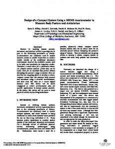
B is reassigned with one step length added and value A is reassigned periodically in direction–c, and the sweep cycle will be stopped until . The tags are set with the reassigned values in each cycle. The code is developed in global action, where any tags can easily call this scanner code to accomplish the two-dimension parameters scan. B. The Optimization Results The scanning result of the output beam current at the entrance of the CRS cavity as a function of solenoids currents is shown in Fig. 9 [7]. The yellow point (345A, 365A) represented the highest beam current. For the beam steering optimization, a four-quadrant diaphragm (4-QD) shown in Fig. 6 was employed. The off centered beam can be monitored from the current in each quadrant. There are four variables of the steering including front X, front Y, back X and back Y. Based on the scanner code, the two variables in X direction were scanned first to minimize the corresponding currents of the diaphragm, then use the best parameters in X direction to optimize the two variables in Y direction. The process should be repeated several times in the same way until the minimized currents in four quadrants were achieved. After the optimization procedures, the measured beam emittance in the point (345A, 365A) was .mm.mrad, and the transmission efficiency of LEBT was up to 87.5%. The twiss parameters of both X and Y directions that satisfy the requirement of CRS cavity would be achieved under the condition of the focusing strength at the above range of the currents as well.
Fig. 9. Beam intensity as a function of solenoids currents.
C. Performance of the System With the fine design in both hardware and software, the system can maintain stable and safe operation for a long time under the circumstances of high voltage and high RF power, as the same for the devices connected with the system. This system integrated more than 80 variables for operating all the devices in CRS linac, and it can be easily extended by introducing more modules and assigning corresponding addresses. The data acquisition rate of the PLC is about several hundred millisecond, which is enough for the normal control. In terms
2350
IEEE TRANSACTIONS ON NUCLEAR SCIENCE, VOL. 61, NO. 4, AUGUST 2014
of the fast control such as AGC/AFC and beam current acquisition, the corresponding circuit boards and data acquisition cards with higher data rate are required and integrated into the control system, which provides multiple types of interfaces for the various communications. V. CONCLUSION A compact PLC control system for the CRS linac was presented in this paper. The system hardware configuration and software design have been accomplished. The devices with different interfaces were integrated into the PLC modules. The high voltage protection maintains the safety of the devices. The AGC/AFC circuit design provides a solution for the automatic control of cavity tuning. All these devices would be controlled and monitored simultaneously by CRS v1.0 software developed in WinCC. All the important tags and operating parameters were archived in SQL database. The interlock system was developed to prevent the damage from the unstable operating conditions. This system was implemented successfully for the operation of the He injector in June 2013. For the beam transmission optimization in LEBT, a scanner code was developed, and the beam experiment results accord well with the requirements of the CRS cavity. REFERENCES [1] L. Lu and T. Hattori et al., “Design and simulation of C hybrid single cavity linac for cancer therapy with direct plasma injection scheme,” Nucl. Instrum. Meth. Phys. Res. A, vol. 688, pp. 11–21, 2012. [2] A. Bechtold and U. Bartz et al., “A coupled RFQ Drift-tube combination for FRANZ,” presented at the LINAC. Conf, Victoria, BC, Canada, 2008.
[3] Z. Wang et al., “Design and measurements of SFRFQ cavity,” Nucl. Instrum. Meth. Phys. Res. A, vol. 607, pp. 522–526, 2009. [4] M. L. Kang et al., “Separated function RFQ beam dynamics design and commissioning,” Nucl. Instrum. Meth. Phys. Res. A, vol. 640, pp. 38–43, 2011. [5] Z. Wang and J. E. Chen et al., “A computer code for beam dynamics simulations in SFRFQ structure,” Nucl. Instrum. Meth. Phys. Res. A, vol. 572, pp. 596–600, 2007. [6] Z. Wang and J. E. Chen et al., “Design of coupled cavity with energy modulated electron cyclotron resonance ion source for materials irradiation research,” Phys. Rev. ST, vol. Accel. Beams 15, p. 050101, 2012. [7] S. X. Peng and J. Chen et al., “Commissioning of helium injector for coupled radio frequency quadrupole and separated function radio frequency quadrupole accelerator,” Rev. Sci. Instrum., vol. 85, p. 02A712, 2014. [8] J. Chen and S. X. Peng et al., “Commissioning of helium injector for coupled RFQ & SFRFQ accelerator,” presented at the IPAC Conf., Shanghai, China, 2013. [9] H. Kleines, J. Sarkadi, F. Suxdorf, and K. Zwoll, “Measurement of real-time aspects of simatic PLC operation in the context of physics experiments,” IEEE Trans. Nucl. Sci., vol. 51, no. 6, pp. 489–494, Jun. 2004. [10] J. Odagiri and S. Araki et al., “Application of EPICS on F3RP61 to accelerator control,” presented at the Particle Accelerator Society Meet., Japan, 2009. [11] L. Dalesio, “The experimental physics and industrial control system architecture: Past, present, and future,” Nucl. Instrum. Meth. Phys. Res. A, vol. 352, pp. 179–184, 1994. [12] W.-X. Zhou and Y.-Y. Wang et al., “Design of a control system for LECR3,” Nucl. Instrum. Meth. Phys. Res. A, vol. 728, pp. 112–116, 2013. [13] [Online]. Available: http://www.automation.siemens.com/mcms/industrial-communication/en/profibus/system-connections-pg-pc/ cp5611/pages/cp5611a2.aspx [14] W. L. Xia and Z. Wang et al., “Design of the tuning system for the He coupled RFQ-SFRFQ cavity,” presented at the IPAC Conf., Shanghai, China, 2013. [15] E. W. Kamen, “Ladder logic diagrams and PLC implementations,” in Industrial Controls and Manufacturing. New York, NY, USA: Academic, 1999, ch. 8, ISBN 0123948509. [16] “Power supply system communication protocol v1.0,” Inst. Modern Physics 2010.