Design, implementation and validation of a software data loading application for avionics equipment in AFDX network using COTS Ethernet Luis Miguel Parrilla Casquet, Enrique Sánchez Blanco Skylife Engineering
[email protected],
[email protected]
José María Caballero Béjar Carbures Engineering
[email protected] Germán Soriano Rull
María Ángeles Martín Prats University of Seville, Senior IEEE,
[email protected]
Airbus Defence and Space
[email protected]
Abstract— The use of loadable systems whose functionality may be changed or updated using onboard loadable software has become one of the most important improvements in aircraft systems design, and has an important impact in the aircraft production process. The current paper describes the design and implementation of a software data loading application for avionics equipment over an AFDX network, developed for Airbus Defence and Space. A standard Ethernet COTS board is employed with no external hardware needed. It is also described the successful testing and integration of the application in the A400M FAL facilities with avionics devices, resulting in a reliable application that showed a performance improvement over the existing data loading system. Thanks to the flexibility achieved, possible future works with the application are introduced. Keywords—dataloading, AFDX, software upload, A615, A665
I. INTRODUCTION In the last two decades a significant number of technological strides in the field of the information technology and communications have been developed. Many of these standards which were not originally intended for use in embedded systems have been successfully adapted and are now widely used in the aircraft industry. The technological evolution has brought a revolution in the conception and design of aircraft systems and has fostered the arousal of new functionalities that have never been used on board before, thanks to the increasing processing power and communication capabilities of the new computer systems and also to the development of applications and work environments more complex but also more time efficient and versatile. Some of the system architectures and technologies that have been developed during this technological breakthrough have been: •
The Controller Area Network (CAN) bus, originally developed by Bosch in the 80s [1] and [2], and implemented in a Mercedes Benz car for the first time in 1992.
978-1-4799-7800-7/15/$31.00 ©2015 IEEE
•
The Avionics Full-Duplex Switched Ethernet (AFDX) network technology based on the standard IEEE 802.3 Ethernet communications and adapted in the ARINC 664 Part 7 standard, [3], for the aviation world. AFDX is a communication network derived from the Ethernet industry standard to which specific services have been added in order to meet the following avionics requirements: Network availability, Data integrity, Network determinism and End to End data routing.
•
The Integrated Modular Avionics (IMA), are computer systems with high processing power and I/O capabilities, which can host different applications systems developed independently of the hardware. The use of IMA systems has contributed to the design of systems based on the development of integrated applications, where the software is the brain of the system, and the hardware is a standard platform able to support any function. See [4] for further information.
During the 80’s and 90’s the systems development was mainly focused on creating more powerful and integrated electronics, with low power consumption. During the 90’s the focus started to move from hardware to software, following personal computers’ tendency. Today, no system can be conceived without a clear vision on its software development plan, being probably the most important part of the system as far as hardware tends to be considered a ‘standard’ platform capable of doing anything which depends only on software running on that platform. Nowadays it is believed that the on-board software has probably been the most important recent revolution in aircraft systems. Some hundreds of software part numbers are now part of the configuration of the recent programs like Airbus A380, A400M or A350, whether only tens of them were previously managed in configuration by the aircraft manufacturer. Software and hardware was managed by the equipment supplier, and once delivered to the aircraft
1990
manufacturer the assembly of hardware and software became an equipment part number. The explosion of software development and management has simplified systems evolution, and has permitted the easy addition of new powerful functionalities, which can also be designed either for manufacturing or maintenance purposes. TABLE I list some figures related to the number of software and hardware parts that need to be managed in configuration and dataloaded 1 in the Airbus A400M and A380 aircrafts.
The DLW has been installed in the A400M FAL as the main component of the A400M FAL Station 45. The Station 45 is fully integrated with the FAL design and the A400M build process. Dataloading activities are carried out in parallel with many other assembly and testing activities performed in the different FAL stations. Aircraft computers are dataloaded before their installation on aircraft is required for aircraft power on. The main functions and capabilities of the A400M DLW are:
TABLE I NUMBER OF SOFTWARE AND HARDWARE AVIONICS PARTS Software & Hardware
A400M
A380
Number of software parts
~1200
~2000
Number of hardware parts
~250
~300
In parallel, the development of test software on computer systems has arisen in order to improve their testability at Final Assembly Line (FAL) and further maintainability. In some systems the operational software of the computer is temporally replaced by test software, which can be controlled from a ground test system. The test software allows reading and writing computers’ discrete, analog and buses I/Os for ground systems tests execution. When developing or modifying systems functionalities, using new software instead of new hardware can help manufactures and operators to reduce the total number of hardware Line Replaceable Units (LRUs) in inventory, increase hardware homogeneity, and reduce airplane modifications time. Moreover this allows operators to change the configuration of loadable systems without physically modifying or replacing hardware components. Benefits include the ability to meet new requirements, incorporate design improvements, and correct errors. In addition, Field Loadable Software (FLS) uploading does not necessarily need to be performed on board the aircraft, but using a ground dataloading station, which simplifies dataloading tasks, saves time and increases aircraft availability. Considering the huge amount of FLS parts to be uploaded into the A400M aircraft equipment and the objective of reducing aircraft manufacturing lead-time and associated costs, a ground dataloading tool has been developed, called Dataloading Workshop (DLW), to perform aircraft computers software uploading on ground before equipment installation on board the aircraft. The DLW performs A400M aircraft equipment dataloading reproducing the necessary aircraft conditions and environment on ground in a shopfloor. It enables to upload FLS in a trustable manner, automatically and repetitively. At equipment level, from a dataloading point of view, there must be no differences between performing dataloading on-board or off the aircraft.
1
•
Simulation of aircraft on ground and necessary dataloading conditions.
•
Equipment configuration for correct equipment power up (hardware pin programming control).
•
Equipment power on/off control.
•
Dataloading protocols implementation and control.
•
Connection to FLS repository to get software parts to be loaded.
•
Connection to configuration management IT tools to get aircraft configuration information.
•
Connection to Manufacturing management IT tools to retrieve and manage Work Orders.
•
Aircraft equipment configuration check and reporting.
The work here presented has been structured in four parts. After this prologue, section II describes the dataloading operations and presents the general scheme and architecture of the developed software dataloader. Section III shows the experimental and validation tests that have been performed using avionics equipment. Finally, conclusions and future works are discussed in section IV. II. DESCRIPTION The work here presented consists in the development and integration of a software dataloader application, called DLWLight, which is intended to perform: 1) Software upload: The main function of the dataloader is transferring data and operational software programs to airborne new generation avionics equipment over a high-speed data interface compliant with ARINC 615A-1 and ARINC 615A-2 [5] protocol standard. The on-board software must be compliant with ARINC Report 665 Loadable Software Standards [6]. A Commercial Off-The-Shelf (COTS) Ethernet interface is employed to implement the ARINC 664/AFDX communication needed to perform the dataloading operations to the avionics equipment. 2) Equipment configuration information reports: the dataloader gets information on the configuration of the Target Hardware, which includes hardware part number and serial number, and software part numbers. The configuration information is displayed in ARINC 615-A compatible format to check operation results and equipment upload state.
Dataload: transfer software into a device
1991
3) Ping requests to avionics equipment through an AFDX avionics network: in order to test the correct connection of an avionics computer to the AFDX network, the Ping command operates sending an Internet Control Message Protocol (ICMP) [7] echo request through the AFDX switching network and waiting for ICMP response. It measures the time from transmission to reception and it records any packet loss. The software dataloader is a C/C++ encoded solution, composed of a software server application that runs in a server and a Human Machine Interface (HMI) application which may be executed in a workstation or laptop. An easy-to-use Graphical User Interface (GUI) specially designed for aircraft dataloading and maintenance operations supporting Windows and Linux is included. The graphical application takes advantage of the cross-platform library Qt, providing an intuitive, robust and cross-platform software tool. It shows graphical information about the dataloading operations and results. The selected operations are gathered and carried out by the software application DLW-Light, turning the user requests into dataloading operations compliant with ARINC 615-A. In the software protocol and communications definition are depicted for the overall system. The three devices involved in the dataloading process are shown: the workstation, the DLW server and the LRU or avionics equipment (the HMI application and the server application can run in the same machine). The communication interface, seen in Fig. 1, between the HMI application running on the workstation and the software DLW-Light running on the server is built with standard TCP/IP sockets. This solution provides flexibility and scalability to the dataloader system. The application allows different users to perform up to 8 parallel dataloading operations simultaneously over different types of equipment located on the test bench. The limit of simultaneous dataloading operations, which could be theoretically expanded by software, is currently bounded by the test bench architecture specifications. Nevertheless, the mentioned limit completely fulfills the dataloading needs
taking into account the current conditions and dataloading processes. The avionics interface presented in Fig. 1, between the LRU and the server is compliant with ARINC 615-A dataloading operation. A multithreaded TFTP server implemented over UDP and IP layers through modified Ethernet frames, according to ARINC 664 / AFDX specification, is implemented in the server running the DLWLight software. The software design for the AFDX interface was built with object-oriented programming techniques and implemented with several commonly-used software design patterns such as abstract factory, factory method and singleton [8], keeping in mind concepts of modularity and interoperability. The current software design for AFDX interface over a COTS Ethernet board is based on previous works [10], [11] and [12] where a communication software layer for ARINC 429 data bus and AFDX for commercial avionics data bus board were presented. The software dataloader general architecture is depicted in Fig. 2. The socket bidirectional connection with the HMI application is controlled and monitored by a dedicated thread which codes and decodes the message exchanges in the HMIDLW interface. The Parsers are C++ classes in charge of reading and interpreting any kind of file, including configuration, ARINC 615-A related or operation files. The Writers are classes and a set of functions that write user, application and dataloading log files. In addition, all the onboard software parts are stored in a so called FLS repository, accessed by a repository management element. Finally, the Dataloader Protocol (DLP) component takes care of the dataloading operation selected by the user. As mentioned above, the thread pool pattern is employed within this interface to achieve 8 parallel dataloading operations over different pieces of equipment. The DLP element follows the ARINC 615-A standard for dataloading operations and it is structured in software layers to fulfill the different protocols shown in [5]: a TFTP multithread server over UDP, IP and AFDX. The IP and AFDX configuration parameters and frames were implemented following the AFDX standard part 7, see [3].
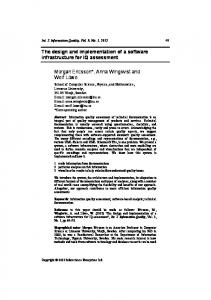
Fig. 1 . DLW-Light Protocol interface Diagram
Fig. 2. DLW-Light Functional Architecture Structure
1992
Fig. 3 compares the architecture of the A400M dataloader used for serial aircraft dataloading and the software dataloader presented in this paper. In the upper part of Fig. 3, a simplistic connection scheme for aircraft equipment dataloading in the A400M DLW is shown. An Ethernet to AFDX protocol conversion device is used between the laboratory software dataloading application and the target LRU. This is a specific device with dedicated hardware and software to perform dataloading operations. The DLW-Light connection scheme is shown below, where unlike the serial dataloading solution, no other additional hardware is needed to set up the communication between the software dataloader application and the LRUs. The DLW-Light application is a software solution that runs in a standard PC and provides cost saving, flexibility and portability. In addition, the software dataloader improves the manufacturing process and reduces maintenance tasks. So far, the main hardware and software architectures of the DLW-Light solution had been presented. The current solution lacks the necessity of extra AFDX hardware, PCMCIA, or PCI devices. This fact leads to some advantages like: simplifying the dataloading tasks, keeping the hardware costs to minimum, improving hardware reuse, saving time, easing maintenance and avoiding equipment obsolescence. Moreover, the DLW-Light application can provide cost saving, flexibility and portability in a demanding environment such as the A400M FAL. The results of the tests performed using on board avionics equipment, are presented in section III. III. SOFTWARE TESTS AND VALIDATION A set of validation tests were carried out in order to verify the performance of the DLW-Light application using equipment from serial aircrafts in the DLW in Airbus Defence and Space A400M FAL in Seville. The HMI of the DLW-Light application was installed in a Windows based workstation, while the software server application was executed in the DLW server which ran on a Debian GNU/Linux 4.0 (Etch) based system. Workstations and server were connected using an Ethernet interface.
The DLW-Light HMI has five functionalities separated into tabs. The Ping application tab is used to check that the target equipment is powered on and therefore available. The Equipment Configuration tab is used to get the information related to the software part numbers already uploaded in the equipment and the hardware serial number and part number of the equipment itself. In the Software Upload tab the user makes the selection of both the software and the target device and launches the uploading operation, while the Upload Progress tab shows in real time the evolution of the upload progress. Finally, the Log tab displays a log application activity for later evaluation. Before starting the tests, the equipment was inserted into a free position of the equipment´s system rack in the DLW. Then, the LRU was powered on, and the dataloading conditions were set allowing the HMI to launch any of the available operations. The tests included the execution of ICMP, Equipment Configuration Information and software Uploading commands. Moreover the automatic software uploading operations could be executed using a set of consecutive uploading operations on one or several LRUs when free racks were available in the DLW. Fig. 4 shows the Upload Progress tab during an upload operation. Each upload operation is shown for separate using a labeled progress bar with a different color code for each upload status. Uploads in progress are shown in blue, aborted uploads in red, and green is used for the completed uploads. A progress indicator text is shown over the progress bar in all cases. All the hardware equipment used during the tests was part of the A400M avionics systems, and the FLSs were uploaded following existing Work Orders. An initial parameter adaptation stage was performed prior to the tests phases in order to set up the configuration parameters of the DLW-Light application to the different interpretations of the protocol ARINC 615-A. Parameters like the maximum file transfer speed or the LRU error communication procedure were modified to check that the communication messages were successfully acknowledged by the target equipment. The performed testing procedure is described below. Firstly an equipment identification command was executed. Secondly the user selected the appropriate aircraft equipment to be dataloaded and the software parts to be uploaded,
Fig. 3. Connection scheme application client vs server
Fig. 4. GUI capture for dataloading operation (Software Upload).
1993
launched the uploading command(s) and waited for a successful upload message. Finally, a second equipment identification command was performed in order to check that TABLE II
TESTED EQUIPMENT
A400 subsystem to which the tested device belongs
Ping
Equip. Conf.
Flight Controls
N/A
OK
Fuel System Digital Map System Flight Management System Integrated Modular Avionics Air Conditioning System High Lift System Head-Up Display Aircraft Condition Monitoring System
OK OK
OK OK
OK
OK
OK
OK
OK
OK
OK
OK OK
OK OK
OK OK
Military Mission System Avionics Data Communications Network Cockpit Display System Integrated Surveillance System Bleed System Air Data Inertial Reference System
Operation SW upload
OK: normal and parallel OK OK OK; normal and sequential OK: normal and sequential
OK
OK
OK
Not tested
OK
OK
OK
OK
OK: normal and parallel
OK
OK
OK: normal and parallel
OK
OK
OK
Not tested Not tested
Not tested
OK
OK
Not tested
the software had been successfully installed in the LRU. An echo Ping request was also sent at the end of the test sequence since some LRUs do not reply to Ping request until all the dataloading operations are successfully finished. In TABLE II, the list of the 16 tested LRUs belonging to 15 different subsystems of the A400M aircraft is shown. The result was labeled as “OK” if the test was successful, “Not available” (N/A) for those devices which did not support the operation, and “Not tested” if the operation could not be performed. Three different software upload operations were executed: •
Normal: A software part was uploaded for every operation.
•
Sequential: More than one software upload operations were uploaded sequentially.
•
Parallel: Several uploading operations were launched in parallel into two devices of the same avionic system.
The performance of the DLW-Light application compared with the current laboratory software uploading application used in A400M FAL, showed a major improvement in terms of dataloading time and data transfer speed. The application adapts its transfer speed depending on the avionics equipment
being loaded, ensuring a fast and safe dataload process. In the case of a device from the Head-Up Display subsystem, the software was uploaded a 35 % faster, for a Digital Map System LRU the speed increment rose to 38 % and when uploading a LRU from the High Lift System the rate raised to the 40 %. Moreover, a substantial increment of the bit transfer rate was recorded during the High Lift System LRU uploading tests. For 8 MB of data files, the transfer speed increased from 39.33 KB/s to 65.42 KB/s when performing the same task. The results of the tests performed with the DLW-Light application showed performance improvements in terms of: • Flexibility. After the initial software parameter set up phase the performance of the application was adapted to all the LRUs under test and to any ARINC 615-A. compliant device that could be tested in the future. • CPU consumption. The software server application was run as a background process and was optimized to lower down the CPU usage to a minimum when no operation is running. • Time saving. The uploading time was significantly low in most of the tests. Because of that, the final application is reliable and flexible to work with any kind of ARINC 615-A compatible device. In general, using the DLW-Light application involves a performance improvement over the existing laboratory application for all the operations, as low CPU and memory usages paired with better software upload speeds were recorded. IV. CONCLUSIONS AND FUTURE WORKS The goal of the work here presented is the design, implementation and test of a software dataloader application to perform dataloading operations to the new generation of avionics equipment that requires high-speed loading, due to the increased size of operational programs and data being loaded (navigation databases, for instance). The AFDX avionics communication is achieved using COTS Ethernet and no extra hardware is required. A wide set of tests were performed in the A400M FAL facilities over computers of 16 different avionics systems. The tests show successful integration in the dataloading station, easy operation, reliability and a considerable time improvement with respect to the current dataloading system. Future works will involve other data buses such as avionics CAN, following the ARINC 826 standard [13], and the use of eXtensible Markup Language (XML) in compliance with the new released ARINC 838 standard [14]. Besides, thanks to its flexible architecture design, the software dataloader proposed herein could be integrated with the current A400M uploading system used for manufacturing purposes. In addition, it is worth to mention that the design and architecture of the well-defined processes of dataloading and configuration reporting could be translated to other industries such as energy and medical safety critical software distribution.
1994
V. REFERENCES [1] [2]
[3] [4] [5] [6] [7] [8] [9] [10]
[11]
[12] [13] [14]
R.Bosh. Can specification, version 2.0. Sttugart. 1991. Giron-Sierra J.M., Insaurralde C., Seminario M., Jimenez J.F., Klose P. "CAN bus-based distributed fuel system with smart components" IEEE Transactions on Aerospace and Electronic Systems, vol.44, no.3, pp.897-912, July 2008. ARINC Specification 664: Aircraft Data Network, Parts 1,2,7 Aeronotical Radio Inc., Tech. Rep., 2002–2005. Richard Garside & F. Joe Pighetti, Jr., “Integrating Modular Avionics: A new Role Emerges.” IEEE Aerospace and Electronics Systems Magazine, March 2009. ARINC Report 615A-1 & 615A-2. Software DataLoader Using Ethernet Interface. ARINC 665-1 & 665-2. Loadable Software Standards. RFC 792. Internet Control Message Protocol. http://qt-project-org/ E. Gamma, R. Helm, R. Johnson, and J. Vlissides, Design Patterns: Elements of Reusable Object-Oriented Software, Prentice Hall; Edición: 1st ed . ISBN-10: 0201633612. L. M. Parrilla, A. Rodríguez, A. Simón-Muela, and M. Prats,"Design and performance of an adaptation middleware interface for a civil avionic bus," Digital Avionics Systems Conference, 2009. DASC '09. IEEE/AIAA 28th , vol., no., pp.6.D.2-1,6.D.2-9, 23-29 Oct. 2009. doi: 10.1109/DASC.2009.5347437 L. M. Parrilla, A. Rodríguez, A. Simón-Muela, and M. M. Prats, “Design of a middleware interface for arinc 429 data bus,” Aerospace and Electronic Systems, IEEE Transactions on, vol. 48, no. 2, pp. 1136–1149, APRIL 2012. L. M. Parrilla, M. Sánchez, F. Guerrero, and M. M. Prats, “Architecture and implementation of a middleware interface for afdx and arinc 429,” XXII AIDAA Conference in Naples, 9-12 September 2013. ARINC 825-2 General Standardization of CAN (Controller Area Network) Bus Protocol for Airborne Use. ARINC Specification 838: Loadable Software Part Definition Format
1995
Powered by TCPDF (www.tcpdf.org)