Application Specific Integrated Circuits (ASICs). A ... the design and use of Application Specific Integrated ..... Synthesis,â Proceedings of the Custom Integrated.
DESIGN OF 2-D FILTERS USING A PARALLEL PROCESSOR ARCHITECTURE Nelson L. Passos Robert P. Light Midwestern State University Wichita Falls, TX 76308
ABSTRACT Two-dimensional filters are usually part of the implementation of digital image processing applications. These filters process recursive sets of instructions and require high computational speed. Optimized implementations of these filters depend on the use of Application Specific Integrated Circuits (ASICs). A system with multiple parallel processing units is a feasible design option able to achieve the required computational performance. In this paper, a loop transformation algorithm, which allows the efficient utilization of a parallel multiprocessor system, is presented. Uniform nested loops representing the image filters and the available processors are modeled as multi-dimensional data flow graphs. A new loop structure is generated so that an arbitrary number of processors available in the system can run in parallel. An example and a description of the algorithm are presented in the paper. Keywords: retiming, nested loops, filter, multiprocessor, image processing.
1. INTRODUCTION Image enhancement and edge detection are wellknown digital image signal processing applications that may require two-dimensional (2-D) filter-like computational solutions. These applications usually depend on computation intensive code sections, consisting of the repetition of sequences of operations. They are also characterized by the multi-dimensionality of the data involved. An effective technique in improving the computing performance of such applications has been the design and use of Application Specific Integrated Circuits (ASICs). This paper presents a new technique applicable to the design of a 2-D filter system using multiple parallel processors. A multi-dimensional retiming algorithm embedded in this new technique provides the fully parallel utilization of the available processors, thus reducing the overall execution time of the filter function. Parallel architectures are an important tool in ASIC design. However, these architectures require a careful partitioning of the problem in order to improve the
Virgil Andronache Edwin H.-M. Sha University of Notre Dame Notre Dame, IN, 46556
utilization of the parallel processors [2, 17, 24]. During the circuit design phase, nested loop structures can be coded using hardware description languages, such as VHDL constructs, in order to reduce the design time. However, in VHDL, the loop control indices will represent the number of times a section of the circuit will be replicated in the final synthesis under the assumption that there are no physical or cost constraints in the circuit implementation [23]. In this paper, a multi-dimensional retiming technique is used to transform the loop in such a way to produce the parallel solution for the problem for a given number of processing units. Such a solution can then be implemented on a standard multiprocessor architecture. Retiming was originally proposed by Leiserson – Saxe, focusing on improving the cycle time of onedimensional problems [13]. Most work done in this area, is subject to limitations imposed by the number of delays (memory elements) existing in a cycle of a data flow graph representing the problem [3, 6, 10, 11, 12, 16, 22, 25]. Other methods focus on multi-processor scheduling and are also applicable to one-dimensional problems [7, 8, 14, 16, 18]. This study focuses on the parallelism inherent to multi-dimensional applications, ignored by the onedimensional methods. Retiming and other loop transformations have since been applied in areas such as scheduling and parallel processing, with the main goal of exploiting fine-grain parallelism in the loop body [4, 15]. Due to the different focus in obtaining parallelism, those techniques are not aimed to improve the execution of parallel iterations in multiprocessor systems. Research by Passos and Sha extended the retiming concept to multi-dimensional (MD) applications [19]. The multi-dimensional retiming concept is used in this paper to model the partitioning of the loop among the available processors. Multi-dimensional retiming brings some advantages to the process, since it is readily applicable to the multi-dimensional fields considered, eliminating the need for a loop transformation that converts the original problem to one dimension. Another significant advantage of MD retiming is that there are no restrictions on its applicability, not being constrained by the characteristics of the one-dimensional methods.
As an example, consider a filter with transfer function: H ( z1, z 2) =
1 1
1
1 − ∑ ∑ g (n1, n2) * z1
− n1
* z2
−n 2
n1=0 n 2 =0
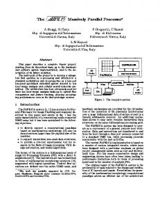
for n1, n2 not simultaneously zero. A multi-dimensional data flow graph (MDFG) can be used to represent this problem as seen in figure 1(a). Figure 1(b) shows a digital circuit design with multiple functional units (multipliers and adders) and memory elements comprising a single processor system designed to solve the filter problem represented in figure 1(a).
optimized will be representative of the iterations being executed in parallel. As an example, Figure 2(a) shows the graph for the filter described earlier, implemented in a two-processor system, however still subject to a sequential execution. After applying the MD retiming operation, the graph will appear as in figure 2(b), where the delays between processors guarantee full parallelism.
(0,1)
(0,1) (0,1) (0,0) (1,1) (1,0)
(0,1)
(0,1) (0,2) (0,1) (1,0) (1,-1)
Figure 2. (a) Multiprocessor graph (b) Retimed graph
Figure 1. (a) MDFG (b) circuit implementation The 2-D delay (1,1) in the MDFG is usually implemented by a FIFO structure equivalent to a serial implementation of z1-1 and z2-1 elements. The delay (0,1) is equivalent to z2-1 and the delay (1,0) to z1-1. The sequential execution time for this design is equivalent to the serial execution of three additions and one multiplication. The nested loop representation of the filter requires a row-wise computation, where the z2-1 element represents only one delay or storage element. Assuming that two identical processors, with the internal design shown in figure 1(b), are available for parallel execution of this loop, an optimization problem arises. The z2-1 delay becomes a direct dependency between two consecutive iterations being executed in the two processors. The same delay also produces a one-delay dependency between two consecutive utilizations of the two-processor system. This implies a non-parallel execution of the two processors, which the 1-D retiming technique cannot change due to the constancy on the number of delays in the cycle involving the two processors and containing the z2-1 delay. Using multidimensional retiming on the MDFG representing the parallel implementation of the circuit, that constraint can be eliminated. In this paper, the focus will be on obtaining parallelism between separate iterations of the loop that can be run on different processors, rather than the fine grain parallelism that optimizes the execution on each individual processing element. As a result, the graph to be
This paper presents the new loop transformation method, based on the multi-dimensional retiming technique, and its applicability to the design of filters implemented in multiprocessor systems. It starts in the next section with an introduction to the basic principles involved, including an overview of multi-dimensional retiming. Section 3 shows the theoretical aspects of the processor allocation technique, followed by a description of the utilization of the method in a more complex example. A final section summarizes the concepts introduced in the paper.
2. BASIC PRINCIPLES A multi-dimensional data flow graph (MDFG) G = (V, E, d, t) is a node-weighted and edge-weighted directed graph, where V is the set of computation nodes, E is the set of dependence edges equivalent to the circuit data paths, d is a function representing the MD delay between two nodes, and t is a function representing the computation time of each node. An iteration is the execution of each node in V exactly once. Iterations are described by a vector w, equivalent to a multi-dimensional index, starting at (0,…,0). Iteration dependencies are represented by vector weighted edges. An edge e from u to v with delay vector d(e) means that the computation of the node v at iteration w depends on the execution of node u at iteration w – d(e). Thus, an edge with delay (0,…,0) represents a data dependence within the same iteration. A legal MDFG
must have no zero-delay cycle, i.e. the summation of the delay vectors along any cycle cannot be (0,…,0). The iteration space of a loop is defined to be the region in the MD discrete Cartesian space whose points correspond one-to-one to the iteration indices. This paper considers loops that present the characteristic of constant dependence vectors, i.e. their data dependencies are at a constant distance in the iteration space. These loops are called uniform loops. Reexamining the example presented in the previous section, the 2-D filter for an image of N by N pixels can be represented by the nested loop below: for (i=0; i (0,0). This theorem can be proven by analyzing three possible cases and considering properties 3.1, 3.2 and 3.3. The three cases are: •
δ(e) = (0,0), which will require the application of the retiming function r, resulting in a dependence δr(e) = δ(e) + r > (0,0).
•
δ(e) = (0,y), according to properties 3.1, 3.2 and 3.3, which after retiming will result in δr(e) >(0,0),
•
δ(e) = (x,y), with x > 0, which would produce δr(e) = (x, y-ry). In this case, considering that x > 0, then δr(e)>(0,0).
Just as in the case of MDFGs, full parallelism is achieved when all edges between any two processors become non-zero delay edges [19]. The loop bodies are then modified according to the retiming function applied to the PDG. Figure 2(b) shows the inter-processor dependencies after the retiming technique was applied to the PDG in figure 3. A synchronization function is now needed to trigger the execution of each processor after an initialization stage, usually called prologue, which is inherent to retiming.
The synchronization function call is controlled by the values of the indices of the loop and the number of the processing unit. When the processor has executed the instructions comprising its mandatory prologue and has already initialized the data required for the parallel execution then the function is activated. The general format of the final code of the loop body for each processor is shown next: Code for processor #n (k =number of processors) for (i = n; i < N; i+k) for (j=0; j(0,…,0)} /* queue non-dependent nodes */ QueueΠ ← QueueΠ ∪ {u ∈ Π, s.t. indegree(u) = 0} while QueueΠ ≠ φ get(u, QueueΠ) /* check if u needs to be retimed */ if ∃ v ∈ Π s.t. δ(u → v) = (0,0) /* adjust the MC(u) value */ MC(u) ← MC(u)+1 MCmax ← max {MC(u),MCmax} endif /* propagate the values to successor nodes of u */ repeat ∀ v ∈ Π such that u → v indegree(v) ← indegree(v)- 1 MC(v) ← max{MC(v), MC(u)} /* check for new non-dependent nodes */ if indegree(v) = 0 QueueΠ ← QueueΠ ∪ {v} endif endrepeat endwhile /* compute the multi-dimensional retiming */ ∀u∈Π r(u) = (0,(MCmax - MC(u))*rv) End
The algorithm MRA will produce the necessary retiming values for each node (processor) represented in the graph, allowing the transformation of the loop into its parallel format.
4. EXAMPLE In this section, the processor allocation algorithm is applied to the IIR section of a 2D-filter design initially presented in [5]. Its transfer function is given by: ∑
2 − j −i ∑ f(i,j)*z 1 *z 2
∑
− j −i ∑ g(i,j)*z 1 *z 2
2
H(z 1 ,z 2 ) =
n1= 0 n 2 = 0 2 2 n1= 0 n 2 = 0
This filter requires a loop with iterations containing eight multiplications and seven additions. The corresponding PDG for a three-processor system, implementing this filter, is shown in figure 4. (0,1)
(0,1)
(0,1)
P0
P1
P2
(1,0)
Figure 4. Processor Dependency Graph for the IIR problem (0,1)
(0,1) (0,1)
P0
(0,1) (0,1)
P1
P2
(1,-2) Figure 5. Retimed PDG for the IIR problem. After applying the multi-dimensional retiming to the processor dependency graph, the PDG changes to the structure presented in figure 5. In this PDG, P0 has been retimed twice using the retiming function (0,1), resulting in an overall retiming value r(P0) = (0,2). P1 has been retimed once, with the overall retiming r(P1) = (0,1). P2 did not undergo retiming and therefore its retiming value is r(P2) = (0,0). These retiming values introduce multidimensional delays in all edges representing dependencies between processors. These new delays represent stored data that allow the parallel execution of the tasks assigned to the different processing elements. The code for processors 0 and 1 under the stated conditions becomes:
k = 3 (number of processors) /* processor 0 */ for (i = 0; i < N; i+k) for (j=0; j