magnetic fi eld to provide a confi ning Lorentz force, which balances the plasma ..... 1st ed., Air Force Research Lab., Kirtland AFB, NM, July 1998. 5Turchi, P. J. ...
JOURNAL OF PROPULSION AND POWER Vol. 18, No. 1, January– February 2002
Design of a Fusion Propulsion System—Part 1: Gigawatt-Level Magnetoplasmadynamic Source
Downloaded by JET PROPULSION LABORATORY on September 2, 2014 | http://arc.aiaa.org | DOI: 10.2514/2.5910
Pavlos G. Mikellides¤ Ohio Aerospace Institute, Cleveland, Ohio 44142 Peter J. Turchi† Los Alamos National Laboratory, Los Alamos, New Mexico 87545 and Ioannis G. Mikellides‡ Science Applications International Corporation, San Diego, California 92121 Optimum travel duration for manned interplanetary missions requires propulsion systems that deliver very high thrust, on the order of a thousand Newtons, in conjunction with speci c impulse capabilities that exceed 10,000 s. Theoretically, rocket propellants consisting of fusion reactants intermixed with large masses of low-molecularweight fuels can be expanded within a magnetic nozzle to meet these requirements. To produce the power levels associated with such systems, a gigawatt pulse line called Godzilla is adapted for experimental development. The megajoule-level energy available is electromagnetically deposited in cold helium gas to simulate the fusionheated, low-molecular-weight propellant. The magnetohydrodynamic computer code, MACH2, is employed to provide guidelines in the design of this magnetoplasmadynamicplasma source. The numerical results specify the geometric con guration and operation conditions required to overcome destructive effects associated with these power levels within experimental limitations.
Nomenclature A Cp J R
= = = = R = ra = rc = T = U; u = z = ® = ° = ± = " = ´ = µ = · = ¹ = ¹o = » = ½ = m =
u ´ ·
area, ¼rc2 .R 2 ¡ 1/, m2 speci c heat at constant pressure, J/kg-K current, A ra =rc universal gas constant, J-amu/K outer electrode radius, m inner electrode radius, m temperature, K, eV velocity, m/s axial coordinate, m average charge ratio of speci c heats characteristic dimension, m current distribution factor electrical resistivity, Ä-m nondimensional temperature, T = Tc thermal conductivity, W/m-K viscosity coef cient, kg/m-s permeability of free space, 4¼ £ 10¡7 H/m nondimensional coordinate, z =± mass density, kg/m3 molecular weight, amu
T
Introduction
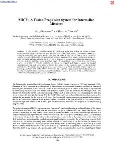
HE reduced transfer times required for human expeditions within our solar system demand high thrust-to-weight, high speci c impulse propulsion systems. Optimum exhaust velocities for nearly straight trajectories range from 200 to 500 km/s.1 At present the leading concept that can meet such speci cations is thermonuclear fusion power. Speci cally, it has been shown that from an overall vehicle-design viewpoint neutron-free, Deuterium-Helium-3 (D-He-3) fusion systems are favorable over Deuterium-Tritium (D-T) systems.1 Temperatures in neutron-free, fusion systems, however, exceed values for “conventional” D-T fusion concepts by factors of about ve (»100 vs 10– 20 keV). Plasma particles from a D-He-3 fusion reactor would have an average speed of 3000 km/s. Even though these velocities are much higher than the optimum values for fast interplanetary travel, fusion reactants can still be utilized to heat a much larger mass of low-molecular-weightplasma (e.g., hydrogen) to stagnation temperatures of »100 eV. The stagnation con nement can be achievedby a magnetic “cusp” con gurationcomposed from proper placement of magnet coils as shown in Fig. 1. Speci cally, the interaction of plasma and magnetic eld (magnetic eld lines of constant ux are depicted as compressed ellipses in Fig. 1) forms a thin layer of diamagnetic currents2 that in turn interact with the magnetic eld to provide a con ning Lorentz force, which balances the plasma pressure-gradient forces. In this manner only a portion of the plasma intermixes with the magnetic eld, providing distinct regions of eld-free plasma and plasma-free magnetic eld. These azimuthal currents are a consequence of the density gradient inside the layer, which results in nonzero Larmor gyration average velocities (diamagnetic drift). The same principles are utilized to subsequently expand the propellant through the main magnetic nozzle and thus provide the optimum speeds. The present paper (Part 1) focuses on the design of a gigawattlevel plasma source that will be used to emulate the stagnation conditions. The source, which is fundamentally equivalent to a
Subscripts
c ex o
= convection = current conduction = thermal conduction
= characteristic = exhaust = stagnation
Received 5 October 2000; revision received 15 July 2001; accepted for c 2001 by the American Institute of publication 20 July 2001. Copyright ° Aeronautics and Astronautics, Inc. All rights reserved. Copies of this paper may be made for personal or internal use, on condition that the copier pay the $10.00 per-copy fee to the Copyright Clearance Center, Inc., 222 Rosewood Drive, Danvers, MA 01923; include the code 0748-4658/02 $10.00 in correspondence with the CCC. ¤ Senior Research Associate, 22800 Cedar Point Drive. Member AIAA. † Chief Scientist, P.O. Box 1663,Mail Stop D410. Associate Fellow AIAA. ‡ Senior Research Scientist, Defense Technology Group, 9455 Towne Center Drive, Mail Stop W2076. Member AIAA. 146
147
MIKELLIDES, TURCHI, AND MIKELLIDES
Downloaded by JET PROPULSION LABORATORY on September 2, 2014 | http://arc.aiaa.org | DOI: 10.2514/2.5910
Fig. 1 Schematic of the fusion propulsion system depicting fusionreactant mixing with injected cold propellant and subsequent acceleration via a magnetic nozzle.
high-power magnetoplasmadynamic (MPD) thruster, will electromagnetically accelerate helium gas that is eventually stagnated by the magnetic cusp. Part 2 (Ref. 3) concentratesin providing insights for the design of the main accelerating magnetic nozzle including issues of proper plasma con nement and stability that directly relate to the cusped arrangement as well. The challenges associated with such power levels call for rigorous and detailed theoretical design. For this we have utilized the MACH2 (Ref. 4) code, one of the most sophisticated magnetohydrodynamic(MHD) numerical tools currently available.
Fig. 2 Schematic of the original inverse-pinch switching system used to deliver the Godzilla current to the load.
Experimental Facility and Preliminary Design A gigawatt-level facility called Godzilla5 at The Ohio State Universitycan providethe necessaryenergy and power levelsto emulate the aforementionedconditions.In its present con guration Godzilla provides approximately 1.6 MJ over a pulse-time of 1.6 ms with a maximum current of 13 MA. Deposition of this energy in a high density propellant can accelerate it to speeds that when stagnated within the magnetic “cusp” will attain the desired stagnation temperatures. To create such a high-current, MPD plasma source, an existing inverse-pinchswitching system6 will be appropriatelymodi ed. In its originalcon guration(see Fig. 2) the singleoutputswitch consists of two copper rings, 35.6-cm inner diameter, 1.25 cm thick, separated by an axial gap of 3.2 cm, initially in a vacuum typically of 1 – 2 torr. The ring electrodes are held apart by a 10.2-cm-long, 28-cm diam stepped-conical insulator. Gas is delivered from the region interior to the rings by breaking the diaphragmof a shock-tubereservoir.The volume of the reservoir is suf cient to supply gas to the switch during the 1.6-ms current pulse. Addition of gas to the interelectroderegion allows the breakdown voltage to drop below the applied voltage. A series of tests6 has con rmed that voltage hold-off is maintained during charging times (several minutes), with the desired breakdown occurring upon arrival of the high-pressure gas. Current ow interacts with the induced azimuthal magnetic eld to create an electromagnetic force on the plasma discharge that is radially outward, i.e., an inverse pinch. Gas ow to the discharge region continues to supply new conducting material so that the discharge location does not change. Plasma is accelerated through this region in a quasi-steady fashion, similar to an MPD thruster at high current. Because the fundamental hardware to provide such type of acceleration is already functional, it is perceived that relatively basic rearrangements, mainly geometric, can direct the high-speed exhaust gas toward a stagnation chamber. In particular, the copper electrodes will be redesigned to produce a con guration of a narrow breakdown/accelerating gap, as shown in Fig. 3. Isentropic stagnation to a desired temperature, as in a supersonic diffuser, can be approximated by
s U2 .1 C ®/C p To D .1 C ®/C p Tex C ex ! Uex ¼ 2
2.1 C ®/° R To .° ¡ 1/m
(1)
Fig. 3 Schematic of the computational setup for the MACH2 simulations depicting computational region (extended to the – – – ), boundary and initial conditions.
under the assumption of a calorically perfect gas and neglecting the exhaust static enthalpy contribution. Thus, design of the geometry and operating conditions of the MPD plasma source can be guided by electromagnetic acceleration to the required exhaust speed ¹o J 2 Uex D 4¼ mP
³
´
ra ¹ J 2 [ .r a =rc / C "] p o C " ! mP ¼ rc 4¼ 2.1 C ®/° R To =.° ¡ 1/m
(2)
where the mass ow rate expression is obtained after substitution of Eq. (1) into the preceding exhaust velocity expression. Specifically, within experimental constraints, Eq. (2) estimates the required mass ow rate to achieve the desired stagnation condition. The radius of The Ohio State University vacuum tank is 30 cm (12 in.), and so the maximum outer electrode radius is limited to 25.4 cm (10 in.). The choice for the dimension of the breakdown/accelerating gap (r a ¡ rc ) depends on the iterative method of minimizing to achieve breakdown at the desired location (Pd Vs V) and maximizing to obtain the target-exhaust velocity.7 For the
Downloaded by JET PROPULSION LABORATORY on September 2, 2014 | http://arc.aiaa.org | DOI: 10.2514/2.5910
148
MIKELLIDES, TURCHI, AND MIKELLIDES
preliminary design a gap of d D 2:54 cm (1 in.) is chosen [i.e., inner electrode radius is 22.86 cm (9 in.)], which implies the preÊ < 40 g/s and exhaust speeds scribed mass- ow-rate range 5 g/s < m 100 km/s < U ex < 190 km/s for variable degree of ionization and current distribution corresponding to 0 < " < 0:75 (Ref. 8). (Associated thrust values range from 948 to 7694N!) Con nement of such high-temperaturestagnated gas cannot be provided by solid matter, rather proper placement of magnetic coils will produce con ning poloidal magnetic elds in a cusped arrangement. However, potential limitations and compromisesassociated with such high energies require a more accurate design. From a numerical perspective the extreme current levels— Ê speci cally, the extreme ratios of 0:225 £ 1013 A2 -s/kg < J 2 /m < 1:8 £ 1013 A2 -s/kg—present a set of unique numerical calculations without guidance from earlier similar efforts within a magnetoplasmadynamic con guration. In particular, the potential for numerical diverging instabilities has been documented at much lower Ê and has been shown to be consistent with physiratios of J2 /m cal phenomena.9 However, we proceeded with relative con dence based on previous simulations of self- eld MPD thrusters with the MACH2 code that have captured experimental trends and magnitudes of terminal variables, current distribution,and current voltage characteristics.10
Numerical Simulations and Analysis The need for accurate design motivates the present effort toward the numerical simulation of the MPD plasma source, using the state-of-the-artunsteady,two-dimensional,axisymmetric,nonideal, MHD code, MACH2. The code was developed in the mid-1980s by the Mission Research Corporation under U.S. Air Force contract to study collisional plasmas for problems of complex geometries.4 The objectives include exploration of the possibility of designing the equivalent of an MPD thruster that produces exhaust speeds on the order of 100 km/s within the geometric constraints of the existing inverse pinch and the hazards associated with gigawatt power levels. The main challenges are associated with producing a con guration that will sustain the current discharge at the location of the accelerating gap, protect insulating material from heat conduction, and minimize radiation effects by minimizing the discharge’s view-factor. Modeling capitalized on the diverse capabilities of the code including thermal nonequilibrium and real equations of state (SESAME 11 ) for the helium gas. The latter provided the thermodynamic properties of the gas including average degree of ionization, which is a critical feature of the exhaust ow. The simulations utilized classical transport with Braginskii coef cients12 that incorporate the tensor nature of the electrical resistivity. The uid was modeled as inviscid with boundary conditions,as depicted in Fig. 3. In particular,the velocityboundaryconditionswere modeledas freeslip, electrode,and insulatorthermalboundaryconditionsconducted heat at appropriateconstanttemperatures.The computationalregion was extended well downstream of the exhaust region to fully capture current distention and acceleration. The dashed lines of Fig. 4 depict these outlet boundary conditions that model variables at zero gradient. Initial conditions,geometry, mass ow rate, and inlet ow pro les varied through the series of simulations and are discussed later; however, Fig. 3 depicts the nal con guration and operating conditions.The currentlevel was set to a constantof 0.3 MA to study steady-state operation with minimized computational expenses; in general, steady state was achieved within 200 ¹s without numerical dif culties. Current Distribution
Initial calculations concentrated in ensuring a breakdown at the acceleratinggap (by prescribingan initialmagnetic eld distribution within the chamber) and examining geometric variations that will maximize exhaust speeds. The iteration demonstrated the bene ts of a rigorous calculation and in particular the need for accurate calculation of the current distribution as a result of diminished expected exhaust-speedimprovements as discussed next. Speci cally, Eq. (2) prescribes improvements that exceed a factor of 1.5 from
Fig. 4 MACH2 steady-state mass density ( ooded contours) and enclosed current (line contours in MegaAmps) distributions.
increasing the gap by only 1– 2 cm; MACH2 simulations showed that the increase is con ned within 10% as a result of variations of the current distribution.Figure 4 depicts the typicalenclosedcurrent distribution calculated by MACH2. By design the outer electrode was longer than the inner electrode, so as to direct the electromagnetic force toward the throat of a decelerating magnetic nozzle. Such con guration would incorporate contributions from both radial and axial acceleration mechanisms, which within the idealized modeling would prescribe" » 0:75 and thus thrust values exceeding 7000 N. However, current distribution variations predicted by the simulations con ned thrust within 2000 N. Gap-size increases (i.e., increasingra =rc ) mainly increasedcurrent distentionover the innerelectrode’s surface, thus minimizing exhaust-speed improvements (i.e., decreasing the effective factor "). Current Con nement
Based on the modeling results, the most important issue is the location of the discharge at steady state relative to the insulating material. It is obviously imperative to con ne the discharge at the minimum-area opening and shield the insulator from excessive heat transfer. This is also a unique requirement imposed on the design as a result of the elevated power levels. We recognized that in order to achieve steady-state operation with the discharge maintained at the breakdown location geometric design and operating conditions should balance the volumetric Joule heating rate and convection cooling at that location. To better guide the computationally expensive simulations, we examined if such balance is possible within operating and geometric constraints by utilizing a simple one-dimensionalanalysis.Speci cally, we can write and nondimensionalize the energy equationfor steady state under the ideal gas and thermal equilibrium assumptions as follows:
³
dT d dT D ´j2 C ½uC p · dz dz dz D
´ )
dµ d»
´c J 2 R±u N2 ·c A±u d ´N j C P p Tc ±´2 mC P p ±·2 d» 2¼ mC
³ ·N
dµ d»
´ (3)
MIKELLIDES, TURCHI, AND MIKELLIDES
149
Downloaded by JET PROPULSION LABORATORY on September 2, 2014 | http://arc.aiaa.org | DOI: 10.2514/2.5910
where the current density squared j 2 is normalized over an area average. Equation (3) also implies the inviscid assumption, which requiresjusti cation.For the geometryand mass ow rates involved, Ê =¹A » 26000 for a the viscous Reynolds number Re D ½u±=¹ D m± characteristiclength of ± » O(2.54 cm) and viscosity coef cient for doubly ionized helium13 of O(10¡6 ) kg/m-s. This, in turn, suggests a boundary-layer thickness of less than a millimeter, validating the omission of viscosity in Eq. (3). For a characteristic discharge temperature of 3 eV and fully doubly ionized helium, ´c D 3:974 £ 10¡4 Ä-m and ·c D 3:16 W/m-K based on the Braginskii transport coef cients utilized by MACH2 that differentiate between parallel and perpendicular components to the magnetic eld.12 For equivalent convection and current conduction characteristiclengths ±u D ±´ » 5:08 cm (approximatelythe length of current conduction shown in Fig. 4) and mass ow rate of the order of 40 g/s, the characteristic numbers de ned by the nondimensionalform of Eq. (3) are of the order of H ´
´c J 2 R±u D 1:63; P p Tc ±´2 2¼ mC
K ´
·c A±u 1:07 £ 10¡5 D 2 mC P p ±· ±·2
(4)
which implies p that thermal conduction operates in an inner layer of order ±· » .1:07 £ 10¡5 /m D 0:33 cm ¿ 5:08 cm, thus convection and Joule heating can be balanced on the order of an outer layer. In other words, for ±· » ±u D ±´ , K » 2:1 £ 10¡4 ¿ 1, and thus thermal conduction is negligible. Within experimental and operational constraints, H » O(1) shows that this balance is achievable; however, it does not reveal the location of the interface, which is determined during the unsteady phase. We can approximate the temperature evolution based on a simple one-dimensional heat diffusion and by consistently assuming a constant characteristic discharge temperature of 3 eV. Then the temperature evolution based on constant thermal conductivity of cold helium, (· » 0:14 W/m-K) is given by14 µ .»; t/ ¡ 1 D erf .» /; µo ¡ 1
z » ´ p 2 ®t
(5)
For a very low-density initial helium ll of the chamber emulating vacuum conditions ½o » 10¡7 kg/m,3 the temperature in the vicinity of the insulator (x » 10 cm) exceeds 2 eV at simulation times of 200 ¹s. This implies that thermal conduction is adequate to elevate the insulator temperatures above tolerable limits and cause catastrophic melting of the insulator. In addition, as the low-density gas is heated in the vicinity of current conduction its electrical conductivity will increase allowing upstream evolution of the current distribution; this will enhance the destructive heating. Numerical simulations that introduced uniform mass ow into a vacuum chamber (modeled at initial density of 10¡7 kg/m3 and 300 K) were performed to more accurately examine the preliminary ndings. Indeed, MACH2 calculated an upstream evolution of the current distribution reaching the vicinity of the insulator. Thermal conduction was more than suf cient to heat the preexisting gas emulating vacuum conditions. This, in turn, increased the electrical conductivity of this low-density gas, allowing current conduction well upstream of the desired location. Convection from the cold in ow (at maximum 40 g/s and 300 K) was insuf cient to contain plasma temperatures [remarkably, of the order 2 eV in accordance to the simpli ed model of Eq. (5)] away from the insulator. Different ignition schemes—mass injection through ports as opposed to uniform mass ow along the insulator—did not alleviate the heating rates; surprisingly steady-state operation was very insensitive to such variations. In addition, geometric variations could not adequately reduce radiative heat transfer by completely shielding the insulator surface from view of the discharge. We recognized that a higher-density gas ll in the chamber prior to the breakdown could ameliorate the situation. Equation (5) suggests that for a heliumdensityof O(10¡5 ) kg/m3 the insulatorsurface temperature would not exceed 400 K. The remedy presents a dual
Fig. 5 Steady-state MACH2 distribution of the heavy-particle temperature.
potential: reduction of heat-conduction rates balanced by convection away from the insulating surface and shielding from radiation effects. Indeed, MACH2 simulations with a chamber initial density of O(10¡5 ) kg/m3 proved quite successfulin con ning the discharge in the vicinity of the accelerating region at steady state as depicted in Fig. 4. Subsequently, a series of numerical iterations ensued that varied the initial density so as to minimize the thermal load to the insulator and ensure exhaust speeds of the order of 100 km/s. Obviously, limitations on the inlet speed and geometric constraints from the experimentalapparatusallowed meaningfulmanipulationsof the mass ow rate, and consequently the exhaust speed [Eq. (2)], only through changes of the initial chamber density. This, in turn, implies that decreasing the chamber density increases the heat-conduction rates to the insulating surface. These computations converged to a range of mass- ow-rate values that will satisfy both criteria, and the results are presented for the value of mP D 12:7 g/s at chamber density of 3:5 £ 10¡5 kg/m3 . Even though heat-conduction rates were greatly diminished, they were not completely eliminated. Figure 5 shows the twodimensional distribution of heavy particle temperature and reveals upstream evolution to the insulator exceeding 1000 K. Speci cally, for this particular chamber density temperature in the vicinity of the insulator (see Fig. 6, top) exceeded 1600 K, a value that would not be toleratedby most insulatingmaterials available.These maximum values occurred closer to the discharge as a result of faster mass depletion (see density distribution in Fig. 4). Some elevated temperature values at the bottom of the insulator occurred as a result of diminished convection cooling (Fig. 6, top). Thus, ensuring the desired exhaust speed values implies that high-tolerance ceramic materials have to be utilized in the fabrication of the MPD plasma source.A very good candidatefor such insulationis alumina ceramic with a melting temperature of 2470 K (Ref. 15). This will easily tolerate the temperature magnitudes predicted by the MACH2 computations. Additional description of the heat-conduction containment and characterizationof the discharge is provided by Fig. 6 (bottom) which displays the electron and heavy-particle temperature pro le along the z direction at a radius of 24.13 cm (9.5 in.), (i.e., a sliced pro le through the middle of the discharge gap). Current is contained beyond 19.05 cm (7.5 in.) from the bottom conductor, which
Downloaded by JET PROPULSION LABORATORY on September 2, 2014 | http://arc.aiaa.org | DOI: 10.2514/2.5910
150
MIKELLIDES, TURCHI, AND MIKELLIDES
Fig. 6 MACH2 temperature pro les. Top: heavy-particle temperature along insulator surface. Bottom: pro les at a radius of 24.13 cm (9.5 in.) (middle of discharge gap).
identi es the thin layer of high thermal gradients of the order of 1.27 cm ( 12 in.) as is generally predicted by the preliminary analysis of Eqs. (3) and (4). These temperature pro les also imply the importance of nonthermal equilibrium as they prescribe discharge electron temperatures of the order of 2.5 eV, but ion temperatures of the order of 2 eV. Further downstream, the discrepancy increases implying more signi cant in uence to the overall energy deposition and consequent exhaust speeds. (Heavy particle temperature decrease is as expected as a result of expansion; however, electron temperatures are increasing implying an increasing degree of ionization.) Further examination of Figs. 4 and 5 shows preliminary indicationsof the desired operationwithin the cusped magnetic eld con guration. Speci cally, the axis of symmetry boundary condition forces partial stagnation of the gas (upper left-hand corner of the two-dimensionalplots), i.e., the radial velocity component,with associated elevated temperatures exceeding 12 eV. Once the secondary magnetic coils are designed and in place—at outer electrode radius and a few centimeters downstream, the exhaust gas will be directed towards the same location, which will be in the vicinity of the throat of the decelerating magnetic nozzle. Exhaust Speed
With containment of the discharge away from the insulator and diminished insulator temperature, MACH2 predicted that the desired exhaust speed magnitudes are achievable as shown by the two-dimensional speed distribution in Fig. 7. The main core of the exhaust gas reaches speeds of the order of 100 km/s. As we progress toward the centerline, these magnitudes decrease to accommodate the axis-of-symmetry boundary condition. Once again the nature of the current distribution directs the ow toward the centerline, which is a very favorable feature that will reduce associated instabilities when interacting with the poloidal magnetic eld lines. These instabilities are shown to be quite signi cant by our examination of magnetic nozzle processes carried out in Part 2 of this effort.3 Some redirection of the ow toward the inner electrode surface lls the region with some low-density, cold gas—also shown in Figs. 4 and 5; however, it is negligible when compared to the main gas core. Figure 8 shows the speed pro le downstream of the
Fig. 7
Steady-state MACH2 speed distribution.
Fig. 8 Steady-state MACH2 pro les downstream of the exhaust depicting plasma speed and average degree of ionization.
acceleratinggas, con rming the computation of the desired velocity magnitudes. Further, Fig. 8 displays the average charge state of the exhaust gas consisting of fully ionized helium (mostly fully doubly ionized). This is another essential objective for the proper operation of the plasma source because it ensures full interaction with the con ning magnetic elds at high electrical conductivity. Final Con guration
The series of iterative numerical simulations with the MACH2 code have resulted in a nal con guration for the experimental design. Within experimental constraints and numerical limitations MACH2 indicates that the necessary high-power MPD thruster/plasma source can be operated and will satisfy the objectives of producing fully ionized helium plasma exhaustingat speeds on the order of 100 km/s. The geometry suggested by the model will utilize a 2.54-cm (1-in.) accelerating gap de ned by inner and outer electroderadii of 22.86 cm (9 in.) and 25.4 cm (10 in.), respectively. The distance between the outer electrode (and consequently the location of the discharge) and the vertical insulatoris maximized
151
Downloaded by JET PROPULSION LABORATORY on September 2, 2014 | http://arc.aiaa.org | DOI: 10.2514/2.5910
MIKELLIDES, TURCHI, AND MIKELLIDES
Fig. 9 Schematic of the nal con guration for the MPD plasma source.
at 24.38 cm (4.4 in.). The length of this vertical insulator will be 20.32 cm (8 in.) for the initialtests. Figure 9 depictsthe geometricalterations to the original inverse-pinchswitch con guration (Fig. 2), along with the inclusion and placement of the new materials as prescribed by the MACH2 modeling. For this geometry operating conditions will utilize helium propellant at a chamber density of 3:5 £ 10¡5 kg/m3 and mass ow rate of 12.7 g/s. For this range of operating conditions,MACH2 predicts that currents of the order of 0.3 MA will be con ned to the accelerating region, providing the desired speeds and producing thrust values in the excess of 1300 N. Heat conduction upstream of the accelerating region results in maximum temperatures in the local gas that do not exceed 1700 K, a value that should be tolerated by the high-strength ceramic materials we plan to utilize for fabrication of the vertical insulator.
Conclusions The design of a high power magnetoplasmadynamic plasma source was successfully undertakenby utilizing the magnetohydrodynamic computer code, MACH2. This plasma source will emulate the stagnation conditions of a fusion-powered propulsion system by utilizing electromagnetic energy form a 1.6-MJ facility to accelerate gas to very high speeds. The deposited kinetic energy will be converted to thermal energy by stagnating the high-speed gas via a magnetic nozzle. The numerical simulations identi ed several concerns to be resolved, such as current distribution and con nement and excessive upstream heat transfer. This was to be achieved within a con guration that was limited by experimental availability and the necessary terminal exhaust speeds and plasma state. Indeed, MACH2 has guided the design toward a nal con guration and operating conditions that resolve the concerns associated with operating a thruster/plasma source at such high power levels and produce the required exhaust speeds.
Acknowledgments The authors express their gratitude for the continued support and encouragement of Craig Williams, NASA John H. Glenn Research Center, Cleveland, Ohio. The effort was supported by NASA John H. Glenn Research Center and the Ohio Supercomputer Center.
References 1 Williams,
C. H., and Borowski, S. K., “An Assessment of Fusion Space Propulsion Concepts and Desired Operating Parameters for Fast Solar System Travel,” AIAA Paper 97-3074, July 1997. 2 Chen, F. F., “Equilibrium and Stability,” Introduction to Plasma Physics and Controlled Fusion, 2nd ed., Vol. 1, Plenum, New York, 1984, pp. 199– 208. 3 Mikellides, I. G., Mikellides, P. G., Turchi, P. J., and York, T. M., “Design of a Fusion Propulsion System, Part 2: Numerical Simulation of MagneticNozzle Flows,” Journal of Propulsion and Power, Vol. 18, No. 1, 2002, pp. 152– 158; also AIAA Paper 00-3367, 2000. 4 Peterkin, R. E., Jr., and Frese, M. H., “MACH: A Reference Manual,” 1st ed., Air Force Research Lab., Kirtland AFB, NM, July 1998. 5 Turchi, P. J., Gessini, P., Mikelldies, P. G., Kamhawi, H., and Umeki, T., “Gigawatt, Quasi-Steady Plama Flow Facility for Fusion Rocket Simulation,” AIAA Paper 98-3592, July 1996. 6 Turchi, P. J., Hohman, K. W., and Kamhawi, H., “Design and Operation of a Quasi-Steady, Inverse-Pinch-Discharge Closing-Switch,” Proceedings of the 10th Inst. of Electrical and Electronics Engineers InternationalPulsed Plasma Power Conference, Albuquerque, NM, 11 – 13 July 1995. 7 Von Engel, A., “Paschen’s Law for Various Gases,” Ionized Gases, Oxford Univ. Press, New York, 1955, Chap. 7, p. 172. 8 Jahn, R. G., “Magnetogasdynamic Description,” Physics of Electric Propulsion, McGraw – Hill, New York, 1968, pp. 240– 246. 9 LaPointe, M., “Numerical Simulation of Geometric Scale Effects in Cylindrical Self-Field MPD Thrusters,” NASA CR 189224, July 1992. 10 Mikellides, P. G., “A Theoretical Investigation of Magnetoplasmadynamic Thrusters,” Ph.D. Dissertation, Aeronautical and Astronautical Engineering Dept., Ohio State Univ., Columbus, Dec. 1994. 11 Holian, K. S., “T-4 Handbook of Material Properties Data Base, Vol lc: EOS,” Los Alamos National Lab., LA-10160-MS, Los Alamos, NM, Aug. 1983. 12 Braginskii, S. I., “Transport Processes in a Plasma,” Review of Plasma Physics, edited by M. A. Leontovich, Consultants Bureau, New York, 1965, pp. 205– 310. 13 Cambel, A. B., “Viscosity,” Plasma Physics and Magnetouidmechanics, McGraw – Hill, New York, 1963, Chap. 7, pp. 184– 186. 14 Kreith, F., and Bohn, M. S., “Transient Heat Conduction” and “Thermodynamic Properties of Gases,” Principles of Heat Transfer, 4th ed., Harper & Row, New York, 1986, Chap. 2, pp. 107– 109, Appendix 2, Table 30, p. 668. 15 Flinn, R. A., and Trojan, P. K., “Optical and Thermal Properties of Materials,” Engineering Materials and Their Applications, 2nd ed., Houghton Mif in, Boston, 1981, Chap. 16, p. 672.