May 1, 2012 - e-mail items. Video compression is a technique used to reduce ... video by reducing the total number of bits by removing all this redundancy.
International Journal of Science and Modern Engineering (IJISME) ISSN: 2319-6386, Volume-1, Issue-6, May 2013
Design of a New Video Compression Algorithm Using Accordion Function Mitesh Shah, Hetal Patel
II. MATERIALS AND METHOLOGIES
Abstract— Among all multimedia applications, transmission of video frames requires large bandwidth and more bytes for storage. To reduce transmission bandwidth and storage memory, video compression is necessary. In this paper our focusing on reducing the storage space for video signal. The proposed technique compresses the video by reducing the spatial, spectral and temporal redundancies of the input video. The temporal redundancy is mainly depending on the co-relation between successive video frames. This redundancy was removed using Accordion function [1]. The accordion function converts the temporal redundancy into the spatial redundancy, which was removed using Discrete Cosine Transform (DCT). The Compression Ratio (CR) achieved for different real time videos was vary from 10 to 30. The CR was found more for those videos having less motion and vice- versa. The values of PSNR was found to be varied between 140 to 155 for different video inputs, while the MSE was varied between 0 to 2.5 for different video inputs.
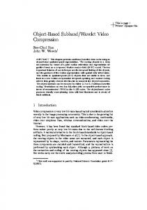
Fig 2.1 shows block diagram of Video compression.
Index Terms— Accordion, Compression Ratio (CR), Peak Signal to Noise Ratio (PSNR), Mean Signal Error (MSE), Discrete Cosine Transform (DCT).
I. INTRODUCTION
V
ideo files are going to touch every area of information technology. Video is incorporated into applications, captured off the TV or the DVD for use as attachments to multimedia e-mail items. Video compression is a technique used to reduce redundancy and so reduce number of bits required to transmit or store video data. Video is a sequence of “pictures” or “frames”. Neighboring pixels in an image are similar shows redundancy, which is called as spatial redundancy. In addition to spatial redundancy, considerable redundancy is often present between a set of frames since only a small portion of each frame is involved with any motion that is taking place. It is called temporal redundancy. The input color video frames represented by 24 bits, (8bits for each Red, Green and Blue color) were consists of high amount of spectral redundancy. The spectral redundancy was reduced by converting the color format from RGB to YCbCr color format. We had compress video by reducing the total number of bits by removing all this redundancy. At decoder side decoding of the compressed data was carried out similarly to get the uncompressed video file back.
Fig 2.1: Block Diagram of Video compression
Video compression process can be divided into four modules: (a) Removal of spectral redundancy (b) Removal of temporal redundancy (c) Removal of spectral redundancy (d) Removal of coding redundancy (a) Removal of Spectral Redundancy : Correlation between different color planes or spectral band is called spectral redundancy. RED, GREEN and BLUE color are called basic colors. Any color can be created by adding different proportion of R, G and B. The amount of R, G or B can be represented by 8 bits for each color, which gives total 24 bits to represent any color. This requires more bits to represent color information of the given frame. It is called spectral redundancy. To reduce number of bits, the RBG color format is converted into YCbCr format. Y represents Luma component of the image, Cb represent chrome for Blue color and Cr represent chroma for Red color. Luma or Luminance shows variation between white to black shades, and chroma shows color information.
Manuscript received May 01, 2012. (Fill up the Details) Mitesh Shah, ECE Department, A. D. Patel institute of Technology, New V.V.Nagar, Gujarat, India. Assoc. Prof. Hetal Patel, ECE Department, A. D. Patel institute of Technology, New V.V.Nagar, Gujarat, India.
40
Design of a New Video Compression Algorithm Using Accordion Function
Fig 2.2 (c) Cb component
The color format of different video frames were converted into YCbCr format using equations (1) to (3) respectively.
Y 0.299R 0.587 0.114...(1) For PAL:
U 0.493( B Y )...(2) V 0.877( R Y )...(3) Fig 2.2 (d) Cr component
PAL is Phase Alteration in Line is a video standard used in India. Fig 2.2 (a) shows the input video frame. When this frame is converted into YCbCr format the resultant images are shown in Fig 2.2 (b) to Fig 2.2 (d), where Fig 2.2(b) shows the luminance values, Fig 2.2(c) shows the Cb values and Fig 2.2(d) shows the Cr values for the input frame.From the input video, different frames were grabbed and assign into structure. Frames of whole structure were converted into YCbCr format.
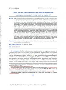
Every four consecutive video frames were used for computation of accordion function. The resultant accordion representation of first four consecutive video frames is shown in Fig 2.6. this step was repeated for all the input video frames. (b) Removal of temporal redundancy: Considerable amount redundancy is often present between a set of frames since only a small portion of each frame is involved with any motion that is taking place. It is called temporal redundancy. Accordion is a method that converts the temporal redundancy into the spatial redundancy[1]. Fig 2.3 shows the concept of temporal redundancy.
Fig 2.2 (a) Video Frame
Fig 2.3 Temporal redundancy
The yellow box (Fig 2.3) contains motion, all other areas were constant this is called temporal redundancy. This redundancy can be converted into spatial redundancy using process called Accordion. Since temporal redundancy is represented as the amount of non-changing data, this constant data in successive frames can be removed by placing the successive frames adjacent to each other. This was done using accordion representation of four successive video frames. In Accordion, group of four consecutive frames were taken and merge to create a single frame/image. Consider the input video of size M x N x 500 bits. Fig 2.4 (a), (b), (c) and (d) shows four consecutive frames and Fig 2.4(e) shows its accordion representation. The corresponding column pixels were places adjacent to each consecutive frame’s column. From input video the consecutive frames from 104 to 108 frame numbers are shown in Fig 2.5 (a), Fig 2.5(b), Fig 2.5(c) and Fig 2.5(d) respectively. The accordion function was computed on these frames , using shift and merge operations, which represents the temporal redundancy as spatial representation(Fig 2.6).
Fig 2.2 (b) Luminance component
41
International Journal of Science and Modern Engineering (IJISME) ISSN: 2319-6386, Volume-1, Issue-6, May 2013 coefficient can be eliminated. The DCT decomposes the signal into underlying spatial frequencies, which then allow further processing techniques to reduce the precision of the DCT coefficients consistent with the Human Visual System (HVS) model. The Discrete Cosine Transform (DCT) has been shown to be near optimal for a large class of images in energy concentration and decorrelating. (d) Removal of codingHuffman Coding: The values derived by DCT are floating point values. These values are positive or negative. To convert values into integer, these values are rounded to nearer integer. After rounding, these values are converted into binary, to transmit them. To convert values from integer to binary and ultimately gain coding redundancy, Huffman coding is done on DCT rounded values.
Fig 2.4(e) Accordion
Fig. 2.5(a) Frame 1
Fig. 2.5(b) Frame 2
Fig. 2.5(c) Frame 3
Fig. 2.5(d) Frame 4
III. RESULTS AND DISCUSSION The research work was carried out between December 2012 to March 2013 at E.C dept., ADIT, NEW V.V.Nagar. Different videos were collected from various sources. Some videos were recorded from 3.2 M.P. mobile camera, 13 M.P professional camera, 16 M.P. digital camera. Some were loaded from internet, CD and DVD. One of the video was truncated from hindi movie. One video was recorded from monitor of PC using software. In this way experiments were carried out on various video sources. There are three terms related to video quality measurement. (a) Mean Square Error (MSE). (b) Peak Signal to Noise Ratio (PSNR). (c) Compression Ratio (CR). (a) Mean Square Error (MSE): Equation for Mean Square Error (MSE) is given by Eq. (4).
Fig 2.6 Accordion of Fig 2.5 (a) to (d)
(c) Removal of spatial redundancy: Neighboring pixels in an image are similar shows redundancy, which is called as spatial redundancy. Purpose of transformation is to convert the data into a form where compression is easier. This transformation will transform the pixels which are correlated into a representation where they are decorrelated. The new values are usually smaller on average than the original values. The net effect is to reduce the redundancy of representation. The DCT function applied on the accordion image is computed using Eq. (2.6).
Where Re,Ge and Be are Red, Green and Blue pixel value from input frame respectively. Rd, Gd and Bd are Red, Green and Blue pixel value from decoded frame respectively. W is the width of frame and H is the height of frame. (b) Peak Signal to Noise Ratio (PSNR):
=
Equation of PSNR is given by:
Where,
...(5)
For i = j = 0 =1
else
Each 28 value is taken for R,G and B pixels.
Discrete Cosine Transform(DCT) is applied to reduce spatial redundancy. Normally human eyes are less sensitive to AC coefficient and highly sensitive to DC coefficient. So AC
(d) Compression Ratio (CR): The equation for CR is given by:
42
Design of a New Video Compression Algorithm Using Accordion Function
Frames are stored into buffer and then decoding is done. This is rest for future work.
….(6) Total nine different videos from different sources were taken and experiment was carried out.
ACKNOWLEDGEMENT The auhors would like to thanks to Dr. Viswajit K. Thaker, Head Of Department, A.D.Patel Institute of Technology, for providing all facilities required to carry out experiments.
The graphs of PSNR, MSE and CR are plotted as below:
REFERENCES [1] Jaya Krishna Sunkara, E Navaneethasagari, D Pradeep, E Naga Chaithanya, D Pavani, D V Sai Sudheer., “A New Video Compression Method using DCT/DWT and SPIHT based on Accordion Representation.”, I.J. Image, Graphics and Signal Processing, 4, 28-34, 2012. [2] Mayank Nema, Lalita Gupta, N.R. Trivedi, “Video Compression using SPIHT and SWT Wavelet” International Journal of Electronics and Communication Engineering.ISSN 0974-2166 Volume 5, Number 1, pp.1-8, 2012.
Fig 3.1 PSNR
[3] Dr.B Eswara Reddy, K Venkata Narayana.,“ A lossless image compression using traditional and lifting based wavelets”, Signal & Image Processing : Signal And Image Processing International Journal, Vol.3, No.2, 2012. [4] S.K Singh, Mahendra Sharma, Priti Singh, Greta Dabre “ Advanced Video Compression Technique of H.264 Codec Using SPIHT Algorithm” International Conference on Recent Trends in Information Technology and Computer Science (IRCTITCS), 2011. [5] Bharathi S.H. , K. Nagabhushana Raju and S. Ramachandran, “Implementation of Horizontal and Vertical Intraprediction Modes for H.264 Encoder”, International Journal of Electronics and Communication Engineering, ISSN 0974-2166 Volume 4, Number 1, pp.105-114, 2011.
Fig 3.2 MSE
[6] Huaqing Wang, Qiang Wu, Xiangjian He, Tom Hintz., “Prelimanary research on fractal video compression on spiral architecture”, Department of Computer Systems,University of Technology, Sydney, 2007. [7] Gary J. Sullivan, Thomas Wiegand, “Video Compression—From Concepts to the H.264/AVC Standard ”, Proceedings of the IEEE, VOL. 93, NO. 1, 2005. [8] Detlev Marpe, Heiko Schwarz, Thomas Wiegand, “Context-Based Adaptive Binary Arithmetic Coding in the H.264/AVC Video Compression Standard”, IEEE Transactions on circuits and systems for video technology, VOL. 13, NO. 7, 2003. Books: [9] Iain E. G. Richardson, H.264 and MPEG-4 Video Compression, 1st Edn, John Wiley & Sons Ltd, 2003, pp 159-222.
Fig 3.3 Compression Ratio
[10] Fred Halsall, Multimedia Communications , 2 nd Edn, Pearson Education Asia , 2006, pp 195-261.
Video 1 is HD quality video captured by HD IV. CONCLUSIONS Results shows that, when video camera quality is good then MSE is less and PSNR is high. So PSNR and MSE depends on quality of video. When motion is large CR is less, so CR depends on motion. This technique is preferable in programs with less motion. Generally NEWS programmes using good quality camera gives good PSNR and CR with less MSE. Four frames are taken simultaneously, ans coded. At receiver side, whole data of full video is send. Decoder takes 4 frames and decode, so real time compression is not possible. To do real time processing, buffer should be there to store frames.
43