ARTICLE International Journal of Advanced Robotic Systems
Design of a Parallel Robot with a Large Workspace for the Functional Evaluation of Aircraft Dynamics beyond the Nominal Flight Envelope Regular Paper
Umar Asif* School of Mechanical & Manufacturing Engineering (SMME), National University of Sciences & Technology (NUST), Islamabad, Pakistan * Corresponding author E-mail:
[email protected]
Received 10 Nov 2011; Accepted 10 Apr 2012 DOI: 10.5772/51430 © 2012 Asif; licensee InTech. This is an open access article distributed under the terms of the Creative Commons Attribution License (http://creativecommons.org/licenses/by/3.0), which permits unrestricted use, distribution, and reproduction in any medium, provided the original work is properly cited.
Abstract This paper summarizes the development of a robotic system for the analysis of aircraft dynamics within and beyond the nominal flight envelope. The paper proposes the development of a parallel robot and its motion cueing algorithm to attain a reasonable workspace with adequate motion capabilities to facilitate the testing of aircraft stall and fault manoeuvrability scenarios. The proposed design combines two parallel mechanisms and aims to provide six degrees of freedom motion with a much larger motion envelope than the conventional hexapods in order to realize the manoeuvrability matching of aircraft dynamics near and beyond the upset flight envelopes. Finally the paper draws a comparative evaluation of motion capabilities between the proposed motion platform and a conventional hexapod based on Stewart configuration in order to emphasize the significance of the design proposed herein.
www.intechopen.com
Keywords Motion Platform; Kinematic Modelling; Real‐ Time Simulation; SimMechanics; Flight Simulator; Motion Cueing
1. Introduction In recent years, with a great number of fatal aircraft accidents and failures, investigations to prevent these fatalities have become of great importance for the research community. Typically, aircraft accidents are attributed to aircraft loss‐of‐control [1] that may involve sensor failure, actuator failure or pilot errors. Upon losing control, the aircraft may quickly deviate beyond the nominal flight envelope into a disturbed condition, causing control to become even more difficult [1‐2]. As a consequence, the analysis of aircraft dynamics near and beyond the nominal flight envelope is a focus of extensive research nowadays. Aircraft dynamics have already been well established for cruise and glide scenarios [3‐10] Int J Adv Robotic 2012, Vol. 9, 51:2012 Umar Asif: Design of a Parallel Robot with aSy, Large Workspace for the Functional Evaluation of Aircraft Dynamics beyond the Nominal Flight Envelope
1
through various methodologies for the analysis under these nominal conditions. However, specific circumstances beyond the nominal or safe flight envelope have not been investigated in as much detail so far. In order to understand and devise methodologies for the prevention of loss‐of‐control situations, we aim to develop a robotic‐test‐bed that may include a dynamically scaled aircraft cabin [11] for exploring the dynamics and control of general transport aircraft. In order to obtain the experimental model of a transport aircraft, we capture the complex nonlinear behaviour of a Boeing 777‐200 within and outside the nominal flight envelope using X‐Plane (a commercially available flight simulator package), a versatile tool that allows engineers to explore the behaviour of aircraft dynamics under nominal and abnormal flight conditions. Though extremely useful, the X‐plane package does not provide closed‐form equations that represent the dynamics of the aircraft, however, it outputs flight data with practical environmental conditions at real‐time, providing an effective opportunity to conduct real‐time hardware‐in‐ loop simulations. Therefore, we use the flight data obtained from X‐plane as reference input to simulate our proposed dynamical model for manoeuvrability matching. In‐flight simulations are considered to be one of the most reliable and practical ways for the evaluation of the manoeuvrability of an aircraft, that is required to simulate nominal and abnormal flight scenarios. Thus, the goal of this paper is to propose a robotic system (a multi‐DOF motion platform), that achieves the desired manoeuvrability matching under nominal and upset flight situations in the presence of environmental disturbances (gust disturbance) which are inevitable in the real world. The rest of the paper is structured as follows: after a description of our proposed design of the motion platform in section 2, the mathematical modelling is described with the aid of forward/inverse kinematic model. Section 3 provides a brief overview of a real‐time simulation model and our motion cueing framework using SimMechanics and Simulink. Section 4 provides the results of closed‐loop dynamic simulations and analysis performed for a test flight plan. Concluding remarks are given in section 5. Literature Review and Related Work Most of motion platforms found in literature are typically based on Stewart configurations [12]‐[17]. Though these typical hexapod configurations provide 6‐DOF motion however, these motion platforms suffer from their limited motion envelope and because of their motion constraints
2
Int J Adv Robotic Sy, 2012, Vol. 9, 51:2012
imposed by the closed kinematic chains they are incapable of achieving large linear and angular accelerations and rates. Researchers have also studied parallel manipulators with less than six legs [36] & [37] to reduce interference between links and simplify the forward kinematics problem. In contrast, the strategy of exploiting serial manipulators as motion platforms has drawn attention for possible improvement in the motion envelopes [18‐24]. Though, a serial six DOF manipulator provides large motion workspace, higher dexterity and the capability to carry heavy loads with much higher accelerations and velocities in comparison to parallel robots. However, exploiting serial manipulators as motion platforms for flight simulation also involves issues such as the unavailability of appropriate kinematic solution and washout filters [25]. In the past few years researchers have proposed double parallel manipulators [11, 12] which are designed with a central axis stacking the two parallel mechanisms. The motion of each parallel mechanism is decoupled and restricted by a common central axis to enlarge workspace and avoid singularities [33]. Generally in a double parallel manipulator each parallel mechanism with two or three linear actuators independently generates the positional or orientation workspace to reduce the interference between links enlarging a compound positional workspace as a consequence. The architecture of a double parallel mechanism is quite different from a conventional Stewart‐Gough platform and there are many problems related to the formulation of its kinematics and dynamics which still require further research and investigations. Another related study [34] describes a double parallel mechanism with its kinematics and addresses the main issues related to the design and manufacturing of double parallel mechanisms. For example, the design of a spline shaft of the central axis which resists torsion loads involves the force and moment analysis at its passive joints which is quite complicated. A much more recent research study [35] has described a new attempt to facilitate the practical usage of a double parallel robot by proposing different combinations of the two parallel mechanisms. A composite six DOF parallel robot is introduced which is a composition of one planar 3‐RPR mechanism and another 3‐UPS mechanism, combined together using a serial connection. Although these research studies propose a robotic platform with a remarkable advantage in the compound positional workspace compared with the conventional Stewart‐ Gough platform, the double parallel robots are a little too far away from the parallelism to take advantage of the
www.intechopen.com
large workspace, but compromise on the stiffness. Moreover, the torsion stiffness is very serious in actual practice and must be improved for a better architecture. Therefore, here we aim to propose the closed‐loop control of a motion platform comprised of hybrid architecture with an attempt to achieve a reasonable motion envelope which conventional hexapods are incapable of achieving. Although our approach can be applied to a large number of vehicles and aircraft dynamics with some changes, we
selected the flight dynamical model of a turbo jet airplane (Boeing 777‐200) as a testing scenario for obtaining experimental evaluation through dynamic simulations. 2. Design and Modelling This section outlines the basic kinematic architecture of our proposed design perceived from the double parallel mechanism idea and develops the forward/inverse kinematic solution for a real‐time motion cueing algorithm.
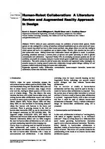
Z-Axis Yaw
Y-Axis
Pitch
X-Axis
Roll Heave Heave: Surge: Sway: Roll: Pitch: Yaw:
Vertical acceleration. Longitudinal acceleration. Lateral acceleration. Angular rate about y-axis. Angular rate about x-axis Angular rate about z-axis.
M4 M5 B5
Surge
M3
B4
M6
M1
B3
M2
B2
G4
B6
G5 G6
Sway
G3 B1 G1
G2
Universal Joint Prismatic Joint Revolute Joint Ground plate coordinate system (fixed) Motion plate coordinate system (moveable) Figure 1. Model of the Proposed Motion Platform
www.intechopen.com
Umar Asif: Design of a Parallel Robot with a Large Workspace for the Functional Evaluation of Aircraft Dynamics beyond the Nominal Flight Envelope
3
z-axis y-axis x-axis M1
Motion Plate
���
��
��
���
��
��
z-axis y-axis
���
B1
��
G1
x-axis
��
��
��� ��
��
Ground Plate ��� : Joint Connecting Link �� and G1 �� : Joint Connecting Link �� and �� : Joint Connecting Link �� and �� �� : Joint Connecting Link �� and �� �� : Joint Connecting Link �� and M1 ��� �� : Active Length of Link Le : Orientation of Link Le ��
Figure 2. Kinematic Configuration of a single actuator
The novelty of the structure lies in the kinematic configuration of this composite architecture (combination of two parallel mechanisms) using a leg design that is composed of two parts: the upper part of the leg constitutes a linear actuator with one actuated revolute joint (θe) and one actuated prismatic joint (le) while the lower part of the leg constitutes a three DOF serial manipulator with two actuated revolute joints (θb, θc) with their motion axes sharing a common plane, further illustrated in Figure 2. The selection of the joints on the ground plate and the moveable plate is based upon the research study conducted in [11]. 2.2 Mathematical Model The objective here is to determine the forward and inverse kinematic equations of the proposed kinematic structure so as to find the appropriate joint rotation angles and active lengths of linear actuators for a required pose. 2.2.1. Forward Kinematic Model From Fig. 2, the position of M1 joint on the motion plate with respect to the ground plate coordinate system can be obtained using homogeneous transformation matrices and Denavit‐Hartenberg convention as given by (1).
B
G
G
B
TM�� � TB�� � TM��
(1)
Where, TM�� is a transformation matrix to obtain the position G
of M1 with respect to B1, TB�� is a transformation matrix to G
obtain the position of B1 with reference to G1 and TM�� relates the position of M1 with reference to G1 (ground frame of 2.1 Architecture of Motion Platform reference). The general transformation expression for relating the position of M1 with reference to B1 can be written The architecture consists of a ground plate represented by as (2) which can be further solved to relate the position of M1 a fixed coordinate system and a motion plate represented with reference to B1 as given by (3). Similarly, the general by a moveable plane in 3D space. Joints G1‐G6 belong to transformation expression for relating the position of B1 with the ground plate and are actuated revolute joints. Joints respect to the ground frame of reference can be written as (4) M1‐M6 belong to the motion plate and are also actuated which can be further solved to relate the position of B1 with revolute joints. The motion plate is connected to the reference to G 1 as given by (5). ground plate through six actuators forming a closed kinematic chain, further illustrated in Figure 1. The joints B1‐B6 are passive universal joints. �����1 0 �����1 �� �����1 ����� ������ 0 ��� ����� ����� ������ 0 ��� ����� � � B� ���� ���� 0 � ���� ����� ����� 0 ��� ����� ��� � 0 ���� � � ��� � � � �� � � � � � � � 1 1 1 �� ��� � (2) TM� � 0 0 1 0 � 0 � 0 0 1 0 1 0 0 0 0 0 1 � � 0 0 0 0 1 0 0 1
G TB��
4
����G� � � � ����G� � 0 � 0
0 0 1 0
����G� �����G� 0 0
Int J Adv Robotic Sy, 2012, Vol. 9, 51:2012
� �� �����1 ��� ��� ��� ������ � �� ���� ��� ����� � � � �� � �� �� � � � ����� �� � � ����� � � � � � ���� � � � �1 � �� � � �� � � �� � � �� � ������ � � � �� � ���� � � �� � � �� � � � � � �
�� ����G� ����� � �� ����G� � � � ����� 0 � 0 � 0 1
������ ����� 0 0
����� 0 �� ����� 0 �� ����� ����� ��� 1 0 0 0 1 0
������ ����� 0 0
0 �� ����� 0 �� ����� � 1 0 0 1
(3)
(4)
www.intechopen.com
� �� �����1 ��� ��� �� ������ � �� ���� �� ����� � � � �� � �� �� � � � ����� �� � � ����� � � � � � ���� � � �1 � � � � � � � � �� � � �� � ������ � � � �� � ���� � � � � � � � �� � �
(5)
�
Substituting (3) & (5) into (1) yields the position of M1 with respect to G1 as given by (6)
� �� �����1 ��� �� � ��� ������ � �� ���� ��� ����� � �����1 ��� � �� �� ������ � �� ��� � �� ����� � � � �� � �� �� � � � ����� �� � � ����� � � � � � ���� � � � � ����� �� � � ����� � � � � � ���� � � � �1 � � � � � � �1 � �� � � �� � � �� � � �� � �� ������� � �� � �� �� ����� ��� ������� � �� � �� ��� ����� � � � � � �
In order to completely describe the moving points Mi of the motion plate in the global frame of reference, the angular rotations of the motion plate in 3D space must be brought into consideration. Body rotations about the three axes are set as shown in Fig. 1 where, psi(ψ) is the rotation of the motion plate about global x‐axis and is termed as pitch, gamma(γ) is the rotation of the motion plate about global z‐axis and is termed as yaw and phi(φ) is the rotation of the motion plate about global y‐axis and is termed as roll. Using general homogenous transformation matrices, the position of a moving point
M1 on the motion plate in the global frame of reference can be expressed by (7) which can be further simplified to (8). In global frame of reference, let ψ, φ, γ represent the rotation of motion plate about x‐axis, y‐axis and z‐axis respectively. Thus, the transformation from the moveable frame of reference to the global frame of reference can be described by a homogeneous transformation expression (pitch‐roll‐yaw orientation) as given by (9). �
��� ��� � ��,� � ��,� � ��,� � ��11
�1 0 ���� 0 ���� ����� 0 0 ��� �1 � 1 0 0� � � ���� ���� 0 0� � �� �1 � � 0 ���� 0 0 0 1 0 �� �1 �� �1 0 0 0 1 ��� � 0 0 1 1�
��
1 0 0 0 ���� ��� �� � �� �� � � �0 ���� ����� 0� � � 0 � � �� � 0 ���� ���� 0 ����� � �� � 0 0 0 0 1 � �� � � �
(6)
(7)
��� � ��� � �� ��1 � ��� � ��� � �� ��1 � ��� � �� ��1 � �� 1 1 � � �� � � � 1 �� �� � � � ���� � ��� � � ��� � ��� � ��� ���� �1 � ���� � ��� � � ��� � ��� � ��� ���� �1 � ��� � ��� � �� �1 � � �1 � �1 �1 � �� � � � �� � ����� � ��� � � ��� � ��� � ��� ��� �1 � ���� � ��� � � ��� � ��� � ��� ��� �1 � ��� � ��� � � �1 � � �1 �� � �1 � � �� �� � � 1
2.2.1 Inverse Kinematic Model
����2��� ��� , �� ��� � � � � � � � 2 ��� � 2 � 2 2 2 2 2 ��2 ���� ����� �� ��� � ��2 ���� ����� �� ��� � � � � � �� �� 2 � 2 �, � ���� � � �����2 ��, �� �� � � ����2�� �� �� � � � � 2�� 2�� ��� � � � � �� �� ����2���� � ��� �� � ��� �� �� , �� ��� �� � �� � ��� �� �� � �� � � � �
����2��� ��� , �� ��� � � � � � � � 2 ��� � 2 � 2 2 2 2 2 ��2 ����� ����� �� ���� � ��2 ����� ����� �� ���� � � � 2 � � �� � �, � � ��� � � �����2 ��, �� �� � � ����2����� ��� � �2 � � 2��� 2��� ��� � � � � �� ����2���� � ��� �� � ��� �� �� , �� ��� �� � ��� � ��� �� �� ��� �� � � �
�� �� Where, � � ��� ���� ������ � � � �� � � � �� ��� ������ � & � � ��� � ������ � � � �� � � � �� � ������ � � �
www.intechopen.com
�
(9)
to achieve the desired motion of the motion plate. Joint angles of a leg are computed using the manipulator inverse kinematic equations as described by (10) and (11).
The objective of the inverse kinematic model is to determine the appropriate joint rotation angles in order
(8)
�
(10)
(11)
�
�
Umar Asif: Design of a Parallel Robot with a Large Workspace for the Functional Evaluation of Aircraft Dynamics beyond the Nominal Flight Envelope
5
Figure 3.Views of the motion platform in different poses.
In order to actuate the prismatic joint in each leg, its active length �� can be obtained from the expression given in (12).
2
�� � ����� � � ��� � 2 �
Where, ��� � �
�
�� �1
1
���� ���
(12)
� �� & ��� � � �� ��1
1
3. Simulation Model with Motion Cueing The goal and contribution of this section is to describe a closed‐loop simulation setup with a motion cueing algorithm in order to generate reference motion trajectories over the motion platform via the kinematics described earlier. Through literature review [19, 20, 25 & 26], it is well understood that motion cueing algorithms using wash out filters have been designed to filter the motion of a high fidelity dynamical model to adequate levels so as to make the motion profiles compatible for a given workspace. Typically the algorithms related to washout filters with tilt‐coordination methods are used for reproducing low‐frequency motions using control frameworks [23‐32]. These methods are considered to be the only feasible alternative as motion cueing algorithm and are still considered to be the most effective because of 6
Int J Adv Robotic Sy, 2012, Vol. 9, 51:2012
their design simplicity, robustness and implementation. Their working is as follows: aircraft dynamics specified in terms of rates and accelerations is split into components of high and low bands, simulating the platform with the high‐frequency components and exploiting the local gravity vector to realize persistent acceleration that is not achievable otherwise [25]. However, due to the motion limits of motion platform, it is realistically impossible to reproduce sustained accelerations larger than 1g and angular motions beyond the rotational motion limits of the motion platform. The simulation model as shown in Figure 5 captures the complex nonlinear behaviour of the aircraft within and beyond the aircraft’s nominal flight envelope and simulates the captured motion cues over the motion platform for advanced simulation, testing and analysis of generic flight dynamics under non‐ideal circumstances. The physical model of the motion platform as shown in Figure 4 is translated from its CAD form into Simulink using SimMechanics toolbox. By exploiting the roll‐rotations of both the motion and the virtual planes, large roll angles and rates can be obtained along angular trajectories. Similar can be achieved with the pitch and yaw rotations in the angular trajectories and heave, surge sway along the translational trajectories. Using the previously described kinematics model, our
www.intechopen.com
proposed motion cueing scheme is illustrated in Figure. 5. The linear accelerations of the aircraft ሾݔሷ ǡ ݕሷ ǡ ݖሷ ሿ் are passed through a high‐pass filter. These linear accelerations expressed in the aircraft frame of reference are first scaled to obtain ሾݔሷ ௦ ǡ ݕሷ ௦ ǡ ݖሷ ௦ ሿ் which are then transformed into the motion plate frame of reference as ሾݔሷ ௦ ெ ǡ ݕሷ ௦ ெ ǡ ݖሷೞ ெ ሿ் . These accelerations are then filtered through a transfer function ܲ ሺݏሻ. The resulting component of the linear acceleration is integrated twice to
F B Revolute3
obtain desired platform displacements as ሾݔ ௦ ெ ǡ ݕ ௦ ெ ǡ ݖೞ ெ ሿ் . The high‐pass filter we employed here is a Butterworth high‐pass filter of the 5th order. Similarly, input angular velocities ሾሶ ǡ ݍሶ ǡ ݎሶ ሿ் of the aircraft are first scaled then transformed into the platform’s motion plate frame of reference. The obtained angular velocities are then high‐pass filtered and finally integrated into the corresponding angular displacement.
A
F B Revolute9
F B Revolute12
Leg 6
Leg 3
F B Revolute4
F B Revolute10 Leg 5
F B Revolute6 Motion Plate
Env
F B Revolute5
F B Revolute8
F Link4
F B Revolute2 Leg 1
Ground Plate
B 2 F Top Motion Plate Revolute4
F B Revolute1 Leg 2
F B Revolute11 Leg 4
[A] From
F B Revolute7
B
Revolute1 Acctuator Upper
[A] Joint Actuator5 From1 Joint Actuator4 [A] From2 Joint Actuator1
B
B
F
Cylindrical Acctuator Lower
B F Spherical 1 Bottom Fixed Plate
B
F
Revolute3
B Link1
[A] [A] From4 Joint Actuator3 From3 Joint Actuator2
F
B
Revolute2
Link2 [A] From5
F
Revolute Link3
Joint Actuator
Figure 4. A) Physical model of the overall motion platform. B) Physical model of a single leg.
www.intechopen.com
Umar Asif: Design of a Parallel Robot with a Large Workspace for the Functional Evaluation of Aircraft Dynamics beyond the Nominal Flight Envelope
7
Fligth Data
Flight Dynamics
Angular rates Accelerations
Filtered Data
High Pass Channel
Accelerations
Filtered Data
Low Pass Channel _.rotation _.translation __01.rotation __01.translation __02.rotation __02.translation __03.rotation __03.translation __04.rotation __04.translation __05.rotation __05.translation __06.rotation __06.translation
Position,Orientation
Joint Angles
Inverse Kinematic Model Position, Orientation
Joint Angles
Forward Kinematic Model
VR Signals
Plant
Pose
VR Signal Expander
Joint Angles
Joint Sensors
Body Position,Orientation
Body Sensors
SimMechanics Sensing Subsystem
VR Sink
Figure 5. Block diagram representation of our motion cueing framework.
4. Experimental Evaluation and Results The flight dynamical model of an aircraft (B777‐200) suitable for a Level‐D type flight simulator was first simulated in real‐time over a conventional hexapod (Moog 6‐DOF2000E) using the simulation model described in Figure 6. Figure 7 shows a view of a conventional hexapod in SimMechanics environment while, Table 1 enlists its motion specifications. In the second run, the same test was repeated using the simulation model of our proposed motion platform. The main focus of this work is to evaluate the motion capabilities of our proposed robotic setup for the functional evaluation of aircraft dynamics beyond the nominal flight envelopes, therefore, the data acquisition methods are not discussed here in detail. In summary, data acquisition was achieved using serial interface RS‐ 232 from sensors and UDP interface for inter‐network data processing.
8
Int J Adv Robotic Sy, 2012, Vol. 9, 51:2012
The abnormal scenario for testing was chosen as follows. A normal trim condition was found at a low‐ speed (52 knots) cruise condition, with a zero flight path angle. Because 52 knots is at the low end of the nominal safe speed for a B777‐200 cruise flight, decreasing the speed or increasing the angle‐of‐attack at this condition induces a fault scenario. To generate a fault condition during the simulation, a control surface failure was replicated by first locking the elevator at ‐ 3.2 degrees beyond the desired trim condition followed by the failure of the aircraft’s left aileron. The failure trajectory was first simulated over a standard hexapod and then using our proposed motion platform in real‐ time for manoeuvrability matching and comparative analysis. The trim condition for the low speed near‐ fault cruise flight was specified by the simulation model as described in Table 2.
www.intechopen.com
B
F
A A 11 A 12 A 13 A 21 A 22 A 23 A 31 A 32
RX_rm From9
LM_ANG
(0 0)
RY_rm
Joint Actuator8
Constant14
From6
From11 RZ_rm
(0
0)
Constant15
From7
(0
[R ,R ,R ] 1
2
3
rad
deg
Angle Conversion1 Display5
Rotation Order: XYZ
Create 3x3 Matrix1 Custom Joint2
Joint Actuator12
Constant6
be
Direction Cosine Matrix to Rotation Angles1
33
Joint Actuator6
0)
DCM
A
CS2
Port 1
B
Port 2
C_RM From RM_new
CS9
B
F
Port 2
(0
0)
Constant8
Joint Actuator
Analytical Kinematic & Dynamic Model CS4
Env
B
F
From8 RM_old
Port 1
(0
0)
Constant7
Joint Actuator7
B RootGround
F Weld6
1
0
Constant
X
-1
0
Constant17
Y
1
0
Constant18
1 Constant19
1 Constant20
1 Constant21
Z
0 RX
0 RY
0 RZ
CS3
CS2
B
RootPart
D is c rete Rate L i it D is c rete Rate L imiter3 D is c rete Rate L i it D is c rete Rate L imiter4 D is c rete Rate L i it D is c rete Rate L imiter5
CS3
CS5
B
From4 LM
F
(0
0)
Constant12
CS6
B
F
(0
RF
Port 1
Joint Actuator5
B
F
Port 1
(0
B
F
HEXAPOD_BOTTOM
(0
0)
Constant9
Joint Actuator1
F
CS6
F
CS7
Revolute4
B -1
From2 LR
CS5
B
Gain
Port 2
Port 1
F Revolute3
-1
From1
C_LR Six-DoF
Joint Actuator3
Port 2
C_RR
CS8
0)
Constant11
RR
Goto5
CS4
B
Port 2
From3
Six-DoF1
F Revolute2
C_LF
CS7
RY
0)
Constant13
LF
Goto4
CS3
B From5
Six-DoF2
F Revolute1
C_RF
PXPYPZ
RX
Joint Actuator4
Port 2
Port 1
Six-DoF3
CS8
B
Port 2
F Weld
D is c rete Rate L i it D is c rete Rate L imiter D is c rete Rate L i it D is c rete Rate L imiter1 D is c rete Rate L i it D is c rete Rate L imiter2
F Revolute6
C_LM Six-DoF4
CS2
B
Port 1
C_RM1 Six-DoF5
F Revolute
(0
0)
Gain1
Constant10
Joint Actuator2
Revolute5 HEXAPOD_TOP_PLATE_A
Goto6
RZ Goto7
Figure 6. Simulation model of a conventional hexapod (Stewart‐Gough configuration with linear actuators).
Parameter Surge Sway Heave Roll Pitch Yaw
Excursion ±0.25m ±0.25m ±0.18m ±21.0° ±22.0° ±22.0°
Velocity ±0.5m/s ±0.5m/s ±0.3m/s ±30.0°/s ±30.0°/s ±40.0°/s
Acceleration ±6.0m/s2 ±6.0m/s2 ±5.0m/s2 ±500°/s2 ±500°/s2 ±400°/s2
Table 1. Motion specifications of Moog 6‐DOF 2000E[33].
Figure 7. A view of a conventional hexapod in SimMechanics.
The fault was simulated as follows: at 70 seconds into the flight, the elevator control surface failure occurred causing the elevator to lock at 5.1°, that is 3.09° beyond the nominal trim condition. The resulting simulation showed that after the failure the aircraft first tilted upwards with an increased angle‐of‐attack causing the aircraft to stall for about 55 seconds and then unexpectedly roll towards its right followed with a decreasing pitch angle. By three minutes into the simulation, the aircraft headed towards a crash under these abnormal flight conditions. Using the real‐time X‐ Plane 3D animations in conjunction with the Simulink simulation model, Fig. 14 illustrates the graphical representation of the extreme behaviour of the aircraft along the fault trajectory.
www.intechopen.com
Figures 8, 9 and 10 show the plots of various flight parameters for the simulated fault flight scenario. As apparent from the figures, the system maintained trim conditions from t = 0 to t = 20 seconds, before the fault was induced. The locked‐elevator fault was induced at about t = 70 seconds causing the aircraft to gain pitch angle. Since the set throttle (30%) was insufficient to provide the aircraft with the necessary lift, the pitching‐ up situation continues without vertical lift for about the next 25 seconds causing the aircraft to stall. The decreasing pitch angle as shown in Figure 8 shows that the autopilot tried to recover the aircraft from the stall situation, but unexpectedly the failure of the aircraft’s left aileron subjected the aircraft to an abrupt roll towards the left which is evident from the increasing roll angle’s profile as shown in Figure 8. The comparative analysis of the reference flight data and the actual simulated data returned by the onboard sensors explain that the hexapod was unable to simulate the required pitch angle during the stall situation since
Umar Asif: Design of a Parallel Robot with a Large Workspace for the Functional Evaluation of Aircraft Dynamics beyond the Nominal Flight Envelope
9
the maximum attainable pitch by the hexapod was 22° as illustrated in Table. 1. Similarly, during the complex motions, the solid plots in Figures 8, 9 and 10 clearly exhibit that the simulated motion cues do not match the reference flight data. Thus, the hexapod was found to be inefficient in investigating and realizing such a fault flight situation at low speed. In contrast, the real‐time simulations carried out using the simulation model of our proposed design with its motion cueing framework resulted in significant
Aircraft Speed Angle of attack Side-Slip angle Angular rates Altitude Angles Control Surfaces Throttle
Ptrim=0deg/sec φtrim = 0.01° uelev = 2.01°
improvement in manoeuvrability matching as apparent from Figures 11, 12 and 13. The close matching of the reference flight data and the simulated motion cues over the motion plate concludes that the proposed kinematic architecture is suitable for simulating flight scenarios with disturbed situations requiring large motion envelopes and improved dexterity. As apparent from Figure 11, the motion platform was able to simulate the high pitch angle during the stall scenario and was also successful at simulating the extreme roll angles near the final crash.
Vtrim = 52 knots αtrim = 11.23° βtrim = 0.1° Qtrim= 0deg/sec Rtrim= 0deg/sec Htrim = 3000ft θtrim = 7.82° ψtrim = 0° uail = 0.019° urudder = 0.036° uthrottle = 30%
Table 2. Trim conditions for the tested fault scenario Rotation Angles (deg)
100
Roll rate(P) Yaw rate(R) Pitch rate(Q)
Roll(phi) Yaw(gamma) Pitch(psi)
0 -100 0 0
2
4
6
8
-100 -200 0 100
2
4
6
8
10
0 -100 0
2
4 6 Time in min
8
0
-20 0 5
10
10
Roll(phi) Yaw(gamma) Pitch(psi)
Sway Heave
6
8
10
0 -5 0 2
Surge
4
2
4
6
8
10
0 -2 0
2 Flight Data Simulated Data
4 6 Time in min
8
10
-5 0 5
2
4
6
8
10
2
4 6 Time in min
8
10
0 -5 0
Linear Accelerations(m/sec 2)
2
6
Figure 10. Comparison of angular velocities.
-1 -2 0 5
4
Flight Data Simulated Data
Figure 8. Comparison of rotation angles
0
2
0
Flight Data Simulated Data
Angular rates (deg/sec)
20
8
10
Rotation Angles (deg)
100 0 -100 0 0
2
4
6
8
10
2
4
6
8
10
2
4 6 Time in min
8
10
-100 -200 0 100 0 -100 0
Flight Data Simulated Data
Figure 9. Comparison of linear accelerations.
Figure 11. Comparison of rotation angles in the second test.
10 Int J Adv Robotic Sy, 2012, Vol. 9, 51:2012
www.intechopen.com
2
Sway
-1
Heave
-2 0 5
2
4
6
8
2
4
6
8
10
0 -2 0
2 Flight Data Simulated Data
4 6 Time in min
8
Figure 12. Comparison of linear accelerations in the second test.
10
Angular rates (deg/sec)
20 0
-20 0 5
10
0 -5 0 2
Surge
Roll rate(P) Yaw rate(R) Pitch rate(Q)
Linear Accelerations(m/sec )
0
1
2
3
4
5
6
7
8
9
1
2
3
4
5
6
7
8
9
1
2
3
6
7
8
9
0 -5 0 5 0 -5 0
Flight Data Simulated Data
4 5 Time in min
Figure 13. Comparison of angular velocities in the second test.
Figure 14. Graphical representation of the fault flight scenario simulated using a standard hexapod.
www.intechopen.com
Umar Asif: Design of a Parallel Robot with a Large Workspace for the Functional Evaluation of Aircraft Dynamics beyond the Nominal Flight Envelope
11
5. Conclusions and Future Work This paper presents a complete framework for the development a multi‐DOF motion platform using the characteristics of a hybrid kinematic configuration. The chief inspiration behind this work is an effort to design a motion platform which may offer a much larger motion envelope in comparison to standard Stewart platform with an opportunity to simulate any potential cabin posture possible within its, an attempt to simulate abnormal flight scenarios which require these enlarged workspaces. This evidently signifies a promising perspective for appliance of motion simulators in the analysis and investigation of aircraft dynamics during upset conditions. In order to take full benefit of such a kinematic architecture, the requirement of a unique inverse kinematic approach and the development of a motion‐cueing framework customized to the particular kinematic design was also our focus in this paper. Simulations were carried out using the proposed motion cueing system in an upset flight scenario. This flight scenario involved challenges namely: extreme pitch and roll rotations and unexpected rates during stall situations. The performance of the controller has been found satisfactory as validated by the comparative analysis of the motion cues simulated by the motion platform and the reference input. The design proposed in this paper is still subject to several enhancements which include the incorporation of an adaptive control algorithm for the cautious regulation of the motion‐cueing system to further enhance simulation realism. The development of the first actual prototype and the construction of a closed cabin with a cockpit have been planned and under future work which is anticipated to contribute in the overall improvement of the simulation fidelity. 6. Acknowledgments The authors would like to thank the anonymous reviewers for their detailed and pertinent comments. 7. References [1] H. G. Kwatny, et al., ʺAircraft Accident Prevention: Loss‐of‐Control Analysis”, Proceedings of the 2009 AAIA Guidance, Navigation and Control Conference, Chicago, IL, August 2009. [2] C. M. Belcastro, ʺValidation and Verification of Future Integrated Safety‐Critical Systems Operating under Off‐Nominal Conditions”, Proceedings of the 2010 AIAA Guidance, Navigation, and Control Conference, Toronto, Ontario, August 2010. [3] J. H. Blakelock, Automatic Control of Aircraft and Missiles, Second Edition ed., 1991.
12 Int J Adv Robotic Sy, 2012, Vol. 9, 51:2012
[4] J. Crouch, “Airplane trailing vortices and their control”, Comptes Rendus Physique, vol. 6, pp. 487‐499, 2005. [5] J. D. Crouch, et al., “Active‐Control System for Breakup of Airplane Trailing Vortices”, AIAA, vol. 39, 2001. [6] H. J. Smith, A Flight Test Investigation of the Rolling Moments Induced on a T‐37B Airplane in the Wake of a B‐747 Airplane, N. F. R. Center, Ed., Edwards, California, 1975, p. 23. [7] R. E. Loucel and J. D. Crouch, Flight‐simulator study of airplane encounters with perturbed trailing vortices vol. 42. Reston, VA, ETATS‐UNIS: American Institute of Aeronautics and Astronautics, 2005. [8] C. W. Schwarz and K. ‐U. Hahn, ʺFull‐flight simulator study for wake vortex hazard area investigation”, Aerospace Science and Technology, vol. 10, pp. 136‐143, 2006. [9] B.‐C. Chang, et al., ʺAircraft Loss‐of‐Control Accident Prevention: Switching Control of the GTM Aircraft with Elevator Jam Failures”, Proceedings of the 2008 AIAA Guidance, Navigation and Control Conference and Exhibit, Honolulu, Hawaii, August 2008. [10] T. L. Jordan, et al., ʺAirSTAR: A UAV Platform for Flight Dynamics and Control System Testingʺ Proceedings of the 25thAIAA Aerodynamic Measurement Technology and Ground Testing Conference, 2006. [11] U. Asif and J. Iqbal, “Modeling, Control and Simulation of a Six‐DOF motion platform for a Flight Simulator”, International Journal of Modeling and Simulation”, pp. 307‐321, Vol. 31, No. 4, 2011. DOI:10.2316/Journal.20.2011.4.205‐5587. [12] Tsai, L.‐W., 1999. Robot Analysis, the Mechanics of Serial and Parallel Manipulators, Wiley, NY, USA. [13] Pernkopf, F. and Husty, M. L., “Workspace Analysis of Stewart‐Gough‐Type Parallel Manipulators”, Proc IMechE J. Mech. Eng. Sci., 220 (2006),1019‐1032, [14] Karger, A. and Husty, M., “Classification of all self‐ motions of the original Stewart‐‐Gough platform”, Computer‐Aided Des., 30 (1998), 205‐215. [15] A, Pisla, N, Plitea, B, Prodan, “Modeling and simulation of parallel structures used as flight simulators”, TMT2oo7, 5‐9 September 2007, Tunisia. [16] N. Plitea, A, Pisla, D, Pisla, B, Prodan, “Dynamic modeling of a 6‐DOF parallel structure destinated to helicopter flight simulation”, ICINCO2008, Madeira (in press). [17] N. Andreff, P. Martinet. Vision‐based Kinematic Modelling of Some Parallel Manipulators for Control Purposes, in Proc. of EUCOMES 2006,Innsbruck, Austria. [18] J. Heindl, M. Otter, H. Hirschmuller, M. Frommberger, N. Sporer, F. Siegert, and H. Heinrich, “The robo‐coaster as simulation platform– Experiences from the “first authentic mars flight simulation”, Proc. of the 1nd Motion Simulator Conference, 2005.
www.intechopen.com
[19] T. Bellmann, M. Otter, J. Heindl, and G. Hirzinger, “Real‐time path planning for an interactive and industrial robot‐based motion simulator”, Proc. of the 2nd Motion Simulator Conference, 2007. [20] L. Pollini, M. Innocenti, and A. Petrone, “Novel motion platform for flight simulators using an anthropomorphic robot”, J. of Aerospace Computing, Information, and Communication, vol. 5, pp. 175– 196, 2008. [21] Robocoaster, “www.robocoaster.com.” [22] K. Beykirch, F. M. Nieuwenhuizen, H. J. Teufel, H.‐G. G. Nusseck, and H. H. Bulthoff, “A roll‐lateral helicopter side‐step maneuver on the MPI motion simulator”, AHS 64th Annual Forum, pp. 1–8, 2008. [23] H.‐G. G. Nusseck, H. J. Teufel, F. M. Nieuwenhuizen, and H. H.Bulthoff, “Learning system dynamics: Transfer of training in a helicopter hover simulator”, Proc. of the AIAA Modeling and Simulation Technologies Conference, pp. 1–11, 2008. [24] P. Pretto, H.‐G. G. Nusseck, H. J. Teufel, and H. H. Bulthoff, “Effect of lateral motion on drivers’ performance in the MPI motion simulator,” Proc. of the Driving Simulation Conference (DSC‐Europe 2009), 2009. [25] P. Robuffo Giordano, C. Masone, J. Tesch, M. Breidt, L. Pollini, and H. H. Bulthoff, “A Novel Framework for Closed‐Loop Robotic Motion Simulation ‐ Part I: Inverse Kinematics Design”, 2010 IEEE International Conference on Robotics and Automation Anchorage Convention District May 3‐8, 2010, Anchorage, Alaska, USA. [26] J. Burki‐Cohen, T. H. Go, and T. Longridge, “Flight simulator fidelity considerations for total airline pilot training and evaluation”, Proc. Of the AIAA Modeling and Simulation Technologies Conference, 2001. [27] Robotic Vision ‐ To 2020 and Beyond, The Strategic Research Agenda for Robotics in Europe. EUROP, 2009. [28] E. L. Groen and W. Bles, “How to use body tilt for the simulation of linear self‐motion”, J. of Vestibular Research, vol. 14, no. 5, pp.375–385, 2004.
www.intechopen.com
[29] B. Siciliano, L. Sciavicco, L. Villani, and G. Oriolo, Robotics: Modelling, Planning and Control. Springer, 2009. [30] P. Chiacchio, S. Chiaverini, L. Sciavicco, and B. Siciliano, “Closed‐loop inverse kinematics schemes for constrained redundant manipulators with task space augmentation and task priority strategy”, Int. J. of Robotics Research, vol. 10, no. 4, pp. 410–425, 1991. [31] J.‐J. E. Slotine and H. S. Yang, “Improving the efficiency of time optimal path‐following algorithms”, IEEE Trans. on Robotics and Automation, vol. 5, no. 1, pp. 118–124, 1989. [32]http://www.moog.com/products/motion‐ systems/motion‐bases/electric‐motion‐basebrmb‐e‐ 6dof‐12‐1000kg‐br‐formerly‐6dof2000e‐/. [33] Min Ki Lee and Kun Woo Park, “Kinematic and Dynamic Analysis of A Double Parallel Manipulator for Enlarging Workspace and Avoiding Singularities”, IEEE TRANSACTIONS ON ROBOTICS AND AUTOMATION, VOL. 15, NO. 6, DECEMBER 1999. [34] Min Ki Lee and Kun Woo Park, “Workspace and Singularity Analysis of a Double Parallel Manipulator”, IEEE/ASME TRANSACTIONS ON MECHATRONICS, VOL. 5, NO. 4, DECEMBER 2000. [35] Yawei Yang, John F. OʹBrien, “Novel Composition of 2 Parallel Robots for 6 DOF Workspace”, Proceedings of the 2011 IEEE International Conference on Robotics and Automation May 9‐13, 2011, Shanghai, China [36] U. Asif and J. Iqbal, Modeling, “Simulation and Motion Cues Visualization of a Six‐DOF Motion Platform for Micro‐Manipulations”, International Journal of Intelligent Mechatronics and Robotics (IJIMR), vol. 1, no. 3, pp. 1‐17, 2011. [37] U. Asif and J. Iqbal, “A Robotic System with a Hybrid Motion Cueing Controller for Inertia Tensor Approximation in Micro‐Manipulations”, International Journal of Advanced Robotic Systems, Vol. 8, No. 4, pp. 235‐247, 2011.
Umar Asif: Design of a Parallel Robot with a Large Workspace for the Functional Evaluation of Aircraft Dynamics beyond the Nominal Flight Envelope
13