Apr 29, 2013 ... Figure 15: Isometric View of the scissor lift design in the storage ..... Figure 52:
Free body diagram (X-Y) plane view of the link 3 (main link) .
Design of a Pool Access Device A Major Qualifying Project (MQP) Report Submitted to the Faculty of the WORCESTER POLYTECHNIC INSTITUTE In partial fulfillment of the requirements for the Degree of Bachelor of Science in Mechanical Engineering By
______________________________ Linjun Bu ______________________________ Patrick Graham
April 29, 2013 Approved
______________________________ Professor E. Cobb, Advisor Mechanical Engineering Department
______________________________ Professor A. Hoffman, Co-Advisor
Abstract January 31, 2013 marked the extended deadline of compliance set forth by the federal government under the revised ADA (American Disabilities Act) specifically for public accessible pools. When a pool is “accessible,” under those standards, it has an entry and exit that accommodates everyone specifically those with disabilities. This act is not limited to public pools but also includes some private businesses such as hotels, spas and wading pools. The pools lifts on the market today can be expensive and also be expensive to install. The goal is to safely move a person in a waterproof chair from the deck of the pool, to over the water, into the pool, and when the user is finished, safely remove them from the pool back to deck. Part of this goal is keeping the chair as horizontal as possible. The design has been developed using the 2010 ADA standards for accessible design. The ADA standards indicate how far the center of the seat of chair should be from the pool, how high the seat of chair should be from pool deck, and how deep the seat of the chair should be submerged below water. The design uses a parallel four-bar linkage mechanism and is able to lift the chair with an average weight person in and out of the pool.
i
Tables of Contents Abstract .......................................................................................................................................................... i Tables of Contents ........................................................................................................................................ ii List of Figures ............................................................................................................................................... iv Acknowledgments....................................................................................................................................... vii Introduction .................................................................................................................................................. 1 Background research .................................................................................................................................... 1 Benchmarking ........................................................................................................................................... 1 Goal Statement ............................................................................................................................................. 4 Task Specifications ........................................................................................................................................ 4 Preliminary design ........................................................................................................................................ 5 Four Bar Design ......................................................................................................................................... 5 Straight-line Linkage Design .................................................................................................................... 10 Pulley/Cable with Slider Design .............................................................................................................. 15 Scissor Lift ............................................................................................................................................... 18 Final design ................................................................................................................................................. 21 Four-Bar Linkage Design ......................................................................................................................... 21 Methodology........................................................................................................................................... 30 Graphical analysis ............................................................................................................................... 31 Exploded views.................................................................................................................................... 37 Position analysis ...................................................................................................................................... 43 Kinematic Analysis .............................................................................................................................. 43 Transmission angle theta .................................................................................................................... 46 Safety factor ............................................................................................................................................ 46 Force and Stress Analysis ........................................................................................................................ 47 Results ......................................................................................................................................................... 76 Final result............................................................................................................................................... 76 Half-Size Physical Model ......................................................................................................................... 78 Conclusion ................................................................................................................................................... 79 Future work/recommendations.................................................................................................................. 80
ii
Recommendation................................................................................................................................ 80 Description .......................................................................................................................................... 80 Resources .................................................................................................................................................... 81 Appendix A .................................................................................................................................................. 82 The Design Chart ..................................................................................................................................... 82 Appendix B .................................................................................................................................................. 87 Position analysis ...................................................................................................................................... 87 Appendix C .................................................................................................................................................. 99 Force analysis Excel Data ........................................................................................................................ 99 Appendix D ................................................................................................................................................ 105 Stress Analysis Excel Data ..................................................................................................................... 105
iii
List of Figures Figure 1: Design specifications of the lift at initial lowering position with the linear actuator fully extended (left) and extreme submerged position (right) with the linear actuator fully retracted. ............. 1 Figure 2: Loading position of the lift with the linear actuator fully extended. ............................................. 2 Figure 3: The assistant is operating the lift to lower the user into the water. ............................................. 2 Figure 4: The top view and the isometric view of the lift. ............................................................................ 2 Figure 5: The side view of the lift. On the left is the chair is in the highest position with the linear actuator fully extended and the lowest position is on the right with the linear actuator fully retracted. .. 3 Figure 6: Front view of the design with extreme high position and extreme submerge position. .............. 6 Figure 7: Top view of the design with loading position and lowering position. ........................................... 7 Figure 8: The core components of the four bar linkage design. ................................................................... 8 Figure 9: Front view of the design with extreme high position and extreme submerge position. ............ 11 Figure 10: Top view of the design with loading position and lowering position. ....................................... 12 Figure 11: The core components of the straight-line linkage design. ........................................................ 13 Figure 12: Front view of the pulley cable with slider design. ..................................................................... 16 Figure 13: Top view of loading and lowering position of the pulley cable with slider design. ................... 17 Figure 14: Core components of the pulley cable with slider design ........................................................... 17 Figure 15: Isometric View of the scissor lift design in the storage position with the actuator partially extended. .................................................................................................................................................... 18 Figure 16: Side view of the scissor lift design in the storage position with the actuator partially extended. .................................................................................................................................................................... 19 Figure 17: Scissor lift as it further developed in the loading position with the actuator fully retracted ... 20 Figure 18: Isometric View of the four bar linkage with the actuator fully extended. ................................ 21 Figure 19: Isometric view of the design with out the chair showing the fourth kinematic link ................. 23 Figure 20: exploded isometric view of the entire design above with the parts list numbers followed by the parts list on page 25. ............................................................................................................................ 24 Figure 21: Front view of the chair with the actuator fully extended and the joints labeled. ..................... 26 Figure 22: Non-Shaded Front view of the device with the actuator fully extended and the joints labeled .................................................................................................................................................................... 27 Figure 23: Front view of the device with the gap redesign. ....................................................................... 28 Figure 24: Rear Isometric view of the device with the actuator extended ................................................ 29 Figure 25: Three position synthesis used to create the linkage design in a side view. .............................. 31 Figure 26: The graphical analysis of the two created links ......................................................................... 33 Figure 27: 3 position graphical Combined for position analysis. ................................................................ 34 Figure 28: 3 position graphical analyses with the Actuator the user. ........................................................ 35 Figure 29: The 3 main assemblies of the device in an exploded isometric view ........................................ 37 Figure 30: Exploded view of the actuator and holder ................................................................................ 38 Figure 31: Exploded view of the actuator holder ....................................................................................... 39 Fi Figure 32: Exploded view of the base .............................................................................................. 40 Figure 33: Exploded isometric view of the linkage system ......................................................................... 41 iv
Figure 34: Exploded view of the chair link 4. .............................................................................................. 42 Figure 35: (X-Y) plane-(Side view) of the design with the actuator fully extended. ................................... 43 Figure 36: kinematic drawing of the links with the actuator fully extended .............................................. 44 Figure 37: kinematic drawings of the links in intermediate position with the chair entering or exiting the water.. ......................................................................................................................................................... 45 Figure 38: Kinematic drawing of design when the actuator fully retracted ............................................... 46 Figure 39: Isometric View of the four bar linkage with the actuator fully extended. ................................ 47 Figure 40: Front view of the chair with the actuator fully extended and the joints labeled. ..................... 48 Figure 41: Exploded view of the chair link 4. .............................................................................................. 49 Figure 42: Free body diagrams for the chair in the X-Y and Z-Y planes. ..................................................... 50 Figure 43: Free body diagram of the supporting bar for the chair. ............................................................ 51 Figure 44: Stress on the chair bar and von mises stress equation. The shear stress equation is also in the figure. .......................................................................................................................................................... 52 Figure 45: Stress on the chair rod and von mises stress equation. The shear stress equation is also in the figure. .......................................................................................................................................................... 53 Figure 46: Stress on the pin H where the angle bar connects to the chair and von mises stress equation. The shear stress equation is also in the figure. .......................................................................................... 54 Figure 47: Free body diagram of the angled chair support. ....................................................................... 55 Figure 48: Stress on the angled bar connects to the chair and straight back support bar with von mises stress equation............................................................................................................................................ 56 Figure 49: Free body diagram straight back bar support that connect the chair and the angled bar ....... 57 Figure 50: Stress on straight back support bar from the angled bar with von mises stress equation. ...... 58 Figure 51: Assembled isometric view of link 3............................................................................................ 59 Figure 52: Free body diagram (X-Y) plane view of the link 3 (main link) .................................................... 60 Figure 53: Free body diagram (Z-Y) plane view of the link 3 (main link) .................................................... 61 Figure 54: Stress on the kinematic link 3 von mises stress equation. ........................................................ 62 Figure 55: isometric view of the base link .................................................................................................. 63 Figure 56: Free body diagram of kinematic link 1 in the X-Y plane ............................................................ 64 Figure 57: Stress on the base link 1 and the von mises stress equation. The shear stress equation is also in the figure. ................................................................................................................................................ 65 Figure 58: Free body diagram of the front wheels in the X-Y plane ........................................................... 66 Figure 59: Exploded view of the actuator and holder ................................................................................ 67 Figure 60: Actuator Assembly Free body diagrams in the X-Y plane. ......................................................... 68 Figure 61: Stress on the Actuator holder and the von mises stress equation. The shear stress equation is also in the figure. ........................................................................................................................................ 69 Figure 62: Stress on the Actuator kinematic links 5 and 6 and the von mises stress equation. The shear stress equation is also in the figure. ........................................................................................................... 70 Figure 63: link 1 base in an isometric view to show the supporting bar underneath the base link ........... 71 Figure 64: x-y plane view of the tank and the wheel .................................................................................. 71 Figure 65: Free body diagram of the square supporting rods in the X-Y plane .......................................... 72 Figure 66: Stress on the base bar under link 1 and the von mises stress equation. The shear stress equation is also in the figure....................................................................................................................... 73 v
Figure 67: Free body diagrams for the l shaped bar supporting the counterweight tanks and wheel free body diagram in the X-Y plane. ................................................................................................................... 74 Figure 68: stresses on the tank base with the von mises equation and shear stress equations. ............... 75 Figure 69: The image above shows the Final result after the design had been iterated numbers times. . 76 Figure70: Materials list for each part.......................................................................................................... 77 Figure 71: The half-size physical model of the pool lift device. .................................................................. 78 Figure 72: (X-Y) plane view (Side view) of the design with the actuator fully extended. .......................... 87 Figure 73: positions 1-2 show the linear actuator (link 5) moving from a stroke length of 20.39 in. as seen on the left to 19 in. as seen on the right..................................................................................................... 88 Figure 74: positions 3-4 show the linear actuator (link 5) moving from a stroke length of 18 in. as seen on the left to 17 in. as seen on the right. ......................................................................................................... 89 Figure 75: positions 5-6 show the linear actuator (link 5) moving from a stroke length of 16 in. as seen on the left to 15 in. as seen on the right.......................................................................................................... 90 Figure 76: positions 7-8 show the linear actuator (link 5) moving from a stroke length of 14 in. as seen on the left to 13 in. as seen on the right .......................................................................................................... 91 Figure 77: positions 9-10 show the linear actuator (link 5) moving from a stroke length of 12 in. as seen on the left to 11 in. as seen on the right..................................................................................................... 92 Figure 78: positions 11-12 show the linear actuator (link 5) moving from a stroke length of 10 in. as seen on the left to 9 in. as seen on the right....................................................................................................... 93 Figure 79: positions 13-14 show the linear actuator (link 5) moving from a stroke length of 8 in. as seen on the left to 7 in. as seen on the right....................................................................................................... 94 Figure 80: positions 15-16 show the linear actuator (link 5) moving from a stroke length of 6 in. as seen on the left to 5 in. as seen on the right....................................................................................................... 95 Figure 81: positions 17-18 show the linear actuator (link 5) moving from a stroke length of 4 in. as seen on the left to 3 in. as seen on the right....................................................................................................... 96 Figure 82: positions 19-20 show the linear actuator (link 5) moving from a stroke length of 2 in. as seen on the left to 1.47 in. as seen on the right.................................................................................................. 97
vi
Acknowledgments We want to give our deepest appreciation to Professor Eben Cobb and Professor Allen Hoffman. The team would also like the team would also like to thank WPI for the opportunity to work on a major project in the mechanical engineering concentration.
vii
Introduction Under the ADA (Americans with Disabilities Act) the federal government has mandated that all pools have handicap access. ADA compliance is required for Title II and Title III pool facilities by January 31, 2013. Both public and private facilities are affected by this new ADA standard for pool lifts. to design a low cost removable handicap access chair for their pools. The problem is to design the mechanism to move a waterproof chair and a person seated in it from above the pool deck into the water.
Background research Benchmarking Aqua Creek Products is a company that builds commercial and residential pool lifts. The company offers different models of the pool lifts, and the main mechanisms they have been using are four-bar and arm swing. This is a manual operation arm swing pool lift from this company. The lift uses a linear actuator with a lever to operate the lift. The submerge position is shown in Figure 1. Figure 2 shows the loading position of the lift. This lift requires an assistant to operate the lift for the user as shown in Figure 3. This model is one of their old products, it does not comply with the new ADA standards because the user cannot self-operate the lift.
Figure 1: Design specifications of the lift at initial lowering position with the linear actuator fully extended (left) and extreme submerged position (right) with the linear actuator fully retracted.
1
Figure 2: Loading position of the lift with the linear actuator fully extended.
Figure 3: The assistant is operating the lift to lower the user into the water.
Spectrum Aquatics manufactures products that are used in construction, operation and maintenance of commercial swimming pools and spas. The company has portable pool lifts that uses four-bar mechanism, and most of their models are powered by linear actuator. The lift shown in Figure 4 is one of the ADA compliant pool lift; the right picture is the isometric view of the product. This product could be both in-ground and on ground pool lift depends on the needs of the facility. The one shown in Figure 4 is the in-ground version. This lift uses four-bar mechanism and it is self-operational. It also has a non-slip grip and a foot rest to increase the safety and user friendliness of the product, the non-slip grip is the overhead transfer assist shown in Figure 5.
Figure 4: The top view and the isometric view of the lift.
2
Figure 5: The side view of the lift. On the left is the chair is in the highest position with the linear actuator fully extended and the lowest position is on the right with the linear actuator fully retracted.
3
Goal Statement Design a pool lift that safely raises and lowers a person from the deck of a pool into the water without tipping the user out of the chair.
Task Specifications The list below is the complete task specifications of our designs. The purpose of the list is to meet the ADA standards and also help the group to design a user friendly product. 1. The lift must be ADA compliant (ADA compliance is required for Title II and Title III pool facilities by January 31, 2013.): o Minimum Lifting Capacity of 300 lbs. o Lift must have a foot rest. o The Assembled lift must be installed where the pool depth does not exceed 48in. unless the entire pool depth is greater than 48in. o The centerline of the seat must be no less than 16in. from the edge of the pool o The mechanism shall be operated in the clear deck space and shall have a slope no steeper than 1:48. o The left edge of the seat must be clear for 36in. to its’ left while clear 36in. from the backrest to out front of the chair and clear 12in. from the backrest of the seat extending behind. o The seat base must be 16in. in width min. o The top of the seat must clear a height of 16-19in. from the ground. o The top of the seat must be submerged at least 18in. when lowering the passenger. o User must be able to operate, without assistance, from the deck and water o Must not require tight grasping, pinching or twisting of the wrists to operate and not require more than 5 lbs. of force. 2. A linkage solution is desired 3. The components of the lift must be corrosive resistant. 4. The components of the lift must be secured the ground before use. 5. The lift must move passengers from the ground into the pool safely and smoothly. The chair must not fall or tip and the operation must stay stable and must not expose the user to unsafe accelerations. 6. Mechanism must not exceed $600. 7. The components of the lift must fit through a door 77in. x 36in. 8. The lift must be sturdy and stable in a wet environment. 9. The lift must be user friendly. 10. The water depth at the access point could be anywhere from 4 feet. 11. Assistant must be able to install the lift in place in 15 minutes or less. 12. Assistant must be able to remove the lift in 15 minutes or less. 13. The lift cannot be permanently attached to the pool deck or sides. 14. The lift cannot damage any tile of the pool or pool area during operation or installation. 15. The lift must move one user at a time. 16. Must sustain long periods of use. 17. The lift should be ideally easy to maintain. 18. The lift should be able to adapt in an outdoor or indoor environment. 19. The lift should be able to adapt to various pool configurations.
4
Preliminary design Four Bar Design The “Four Bar design” design consists mainly of a four metal links, a linear actuator motor to move the links attached to the chair up and down the z-axis as shown in (Fig.6). The other important parts of this design are the bases 1 and 2, the motor in base one that rotates the chair 90°about the z-axis, and the chair that attaches to the four metal links (B) with a series of bolts and screws. The design will be placed pool side where the water does not exceed 4 ft as shown in (Fig.6) unless the entire pool has a depth greater than 4 ft. The design also must be set up in a location where there is 12 in. free from behind and 36 in. free from the edge of the chair opposite the pool as shown in (Fig.7).The next section describes the parts and function of each part. Base 1 in (Fig.6) will house a motor that turns Base 2 90°about the z-axis as seen in the top view of the design in (Fig.7) with the help of a gear system (A) shown in (Fig.8). Base 1 has wheels attached to bottom for portability. The wheels will lock into place to ensure it is fixed in the desired location. Each base is 3ft. by 3ft as shown in the top view (Fig.7). The top base (base 2) will accommodate the linear actuator (C) shown in (Fig.8) as seen in the core components view. Base 2 has the attachment points for the linkage system (Fig.8). The Rotating gear system (A) consists of an inner gear and an outer gear to control the speed of the motor rotating base 2.A motor will be bolted in base 1 to drive the inner gear of the rotating gear system. (Fig.7) shows the top view of the system. The four bar mechanism (B) also showed in (Fig.8) illustrates the linear actuator motor and its connection to the lower metal link (Link 2). The links attach to the chair in four locations to improve stability. The motor will be bolted to the inside of base 2. The four bar mechanism attaches one link to base 2 on one side, the third link is the chair attaching to the metal links through a pin joint, the fourth link attaches to the upper part of the chair and back to base 2 on the upper attachment point. The configuration is repeated on the other side of base 2 as shown in (Fig.6) and (Fig.8). The four bar mechanism essentially translates the patient up and down the z-axis but moves the chair through rotations about the y-axis as shown in (Fig.6). The chair will move 18 in. below the water line allowing for the user to enter the water and complying with the ADA standards.
5
Figure 6: Front view of the design with extreme high position and extreme submerge position.
6
Figure 7: Top view of the design with loading position and lowering position.
7
Figure 8: The core components of the four bar linkage design.
8
Table 1 show the operation steps and the power options that could be used for the four bar design. Table 1: Operation steps and the power options that could be used for four bar design.
Steps Step 1
Four Bar Operation Turning user 90°to load position
Step 2
Rotate the bars to put user into water
Step 3
Lift the User out of the water
Step 4
Rotate 90°back to standby position
9
Power Sources 1. A motor can be attached to a gear system to turn the base part, shown in Figure 7. 1. A motor can be attached to a gear system that is on the pin joints of the mechanism to drive the bars, shown in Figure 6. 2. A linear Actuator can be attached to L2 to drive the bars, shown in Figure 6. 1. A motor can be attached to a gear system that is on the pin joints of the mechanism to drive the bars, shown in Figure 6. 2. A linear Actuator can be attached to L2 to drive the bars, shown in Figure 6. 1. A motor can be attached to a gear system to turn the base part, shown in Figure 7.
Straight-line Linkage Design The “Straight line Linkage” design consists mainly of a four metal bar links, a slot to limit the movement of the of the link that is connected to the chair to one translation up and down the zaxis, a linear actuator motor to power it that is attached to link 3 all of which is shown in (Fig.9). The other important parts of this design are the bases 1 and 2, the motor in base one that rotates the chair 90°about the z-axis, and the chair that attaches to the sliding mechanism (C) with a series of bolts and screws. The design will be placed pool side where the water does not exceed 4 ft. as shown in (Fig.9) unless the entire pool has a depth greater than 4 ft. The design also must be set up in a location where there is 12 in. free from behind and 36 in. free from the edge of the chair opposite the pool as shown in (Fig.10).The next section describes the parts and function of each part. Base 1 in (Fig.9) will house a motor that turns Base 2 90°about the z-axis as seen in the top view of the design in (Fig.10) with the help of a gear system (A) shown in (Fig.11). Base 1 has wheels attached to bottom for portability. The wheels will lock into place to ensure it is fixed in the desired location. Each base is 3ft. by 3ft as shown in the top view (Fig.10). The top base (base 2) will hold the linear actuator (C) shown in (Fig.11) as seen in the front view. Base 2 also holds the entire linkage system (Fig.9). The rotating gear system (A) consists of an inner gear and an outer gear to control the speed of the motor rotating base 2.A motor will be bolted in base 1 to drive the inner gear of the rotating gear system. (Fig.9) shows the top view of the system. The linear actuator motor (B) also showed in (Fig.11) illustrates the motor attaching to link three which will move the third link to create the straight line motion with link 5. The motor will be bolted to the inside of base 2. The rack (C) will complement the T-insert inside it when as shown in (Fig.10) and (Fig.11) will be attached to base 2. This slider insert is meant to keep link 5 vertical to ensure it has one translation to ensure it is a straight line linkage. The slider (C) mechanism as shown as a top view in (Fig.10) shows the configuration of the slider to keep the chair from disconnecting and unnecessary movement. The C shaped rack wraps around the T shaped insert. The T-shaped insert (D) shown in (Fig.11) will be bolted to the chair. The slider is meant to allow the n as seen in (Fig. 9) translation of the chair in the z-axis as shown in (Fig.9). The chair will move 18 in. in the negative z direction below the water line allowing for the user to enter the water and complying with the ADA standards.
10
Figure 9: Front view of the design with extreme high position and extreme submerge position.
11
Figure 10: Top view of the design with loading position and lowering position.
12
Figure 11: The core components of the straight-line linkage design.
13
Table 2 is the operation steps and the power options that could be used for Straight-line linkage design. Table 2: operation steps and the power options that could be used for Straight-line linkage
Steps Step 1
Straight-line linkage Operation Turning user 90°to load position
Step 2
Lower link 3 into the water with the user in the chair
Step 3
Raise the user out of the water
Step 4
Turn the user back to the standby position
14
Power Sources 1. A motor can be attached to a gear system to turn the base part, shown in Figure 10. 1. A motor can be attached to a gear system that is on the pin joints of the mechanism to drive the bars, shown in Figure 9. 2. A linear Actuator can be attached to L3 to drive the bars, shown in Figure 9. 1. A motor can be attached to a gear system that is on the pin joints of the mechanism to drive the bars, shown in Figure 9. 2. A linear Actuator can be attached to L3 to drive the bars, shown in Figure 9. 1. A motor can be attached to a gear system to turn the base part, shown in Figure 10.
Pulley/Cable with Slider Design The “Pulley Cable with a Slider” design consists mainly of a cable, a wheel to limit the movement of the cable, a motor to power it that is attached to a gear system and a drum, and a slider mechanism to limit the freedom of the chair to one linear translation up and down the z axis as shown in (Fig.12). The other important parts of this design are the bases 1 and 2, the motor in base one that rotates the chair 90°about the z-axis, and the chair that attaches to the sliding mechanism (D) with a series of bolts and screws. The design will be placed pool side where the water does not exceed 4 ft. as shown in (Fig.12) unless the entire pool has a depth greater than 4 ft. The design also must be set up in a location where there is 12 in. free from behind and 36 in. free from the edge of the chair opposite the pool as shown in (Fig.13).The next section describes the parts and function of each part. Base 1 in (Fig.12) will house a motor that turns Base 2 90°about the z-axis as seen in the top view of the design in (Fig.13) with the help of a gear system (A) shown in (Fig.14). Base 1 has wheels attached to bottom for portability the wheels will lock into place to ensure it is fixed in the desired location. Each base is 3ft. by 3ft as shown in the top view (Fig.13). The top base (base 2) will house the pulley motor (B) shown in (Fig.14) as seen in the front view. Base 2 also holds the pulley’s cable, the pulley wheel (C), and the sliding mechanism (D) shown in (Fig.14). The Rotating gear system (A) consists of an inner gear and an outer gear to control the speed of the motor rotating base 2.A motor will be bolted in base 1 to drive the inner gear of the rotating gear system. (Fig.13) shows the top view of the system. The pulley motor (B) also showed in (Fig.13) illustrates the motor and drum that will have the cable attached to it. The cable will roll in between the walls attached to the motor box. The motor will be bolted to the inside of base 2. The Pulley wheel (C) as shown in (Fig.12) and (Fig.13) will be attached to base 2 by two bars and a pin joint to allow rotation of the wheel but keep it in place. The slider (D) mechanism as shown as a top view in (Fig.14) shows the configuration of the slider to keep the chair from disconnecting and unnecessary movement. The C shaped rack wraps around the T shaped insert. The T-shaped insert (D) shown in (Fig.14) will be bolted to the chair. The slider is meant to allow the translation of the chair in the z-axis as shown in (Fig.12). The chair will move 18 in. below the water line allowing for the user to enter the water and complying with the ADA standards.
15
Figure 12: Front view of the pulley cable with slider design.
16
Figure 13: Top view of loading and lowering position of the pulley cable with slider design.
Figure 14: Core components of the pulley cable with slider design
17
Scissor Lift
Figure 15: Isometric View of the scissor lift design in the storage position with the actuator partially extended.
Figure 15 shows an Isometric view of the entire scissor lift preliminary design in the storage position. The parts list for each figure is on the following page. In this position the chair sits on the rails (part 9). This storage position will allow the design to be more compact than the previous design for storage. The supporting rod is the next part that will be explored to collapse for storage.
18
Figure 16: Side view of the scissor lift design in the storage position with the actuator partially extended.
Figure 16 shows a side view of the design in the storage position. In this view you can see how the chair rests on the rails and also the slider wheels in the slider link. The wheels are represented by part 11. Parts List Table
1
Counter weight tank
7
Electronic Actuator
2
Top Chair Support
8
Supporting Link
3
Scissor Link
9
Rectangular Slot Rails
4
Supporting rod
10
Slider wheel
5
Chair Supporting Link
11
Supporting Wheels
6
Chair
12
Horizontal Scissor Link
19
Figure 17: Scissor lift as it further developed in the loading position with the actuator fully retracted
This figure shows the evolution of the scissor lift. The chair is now positioned to allow the user to slide in from the side of the chair away from the edge of the pool. This was our last design before returning to a four bar linkage. The design chart is located in appendix A. the results of that design chart would indicate that the linkage rack chain scored the highest based on our criteria. After repeated attempts at revising each design the four bar linkage would be the most feasible.
20
Final design Four-Bar Linkage Design
J Linkage System B C2
Linear Actuator
C2 C1
Water Tanks
Y
Chair
D1
Z
D2
X
F
Base Figure 18: Isometric View of the four bar linkage with the actuator fully extended.
The team has chosen the alternative parallel four bar linkage as the main design because of the limitation of the two previous designs. The team had set out to reduce the motion of the user into the water and this design only has one rotation. The number of parts has also decreased from the two previous designs. The scissor lift and the straight line linkage design required two actuator motors to attempt to achieve the overall goal of placing the user into the water. This linkage requires only one actuator. The other two designs were really large. They would not have been easily stored. The scissor set is 73 inches tall and the straight line linkage failed to reach the desired depth required by the ADA standards. This design is also more simplistic than the 21
previous two complex designs. The following document has the graphical method used to create the full scale design, the kinematic analysis, exploded view of the parts, and the force calculations (this document contains only the drive link and actuator force). The design is actually a six bar because of the power source. The actuator is considered 2 links.
22
J
Link 3 Link 6
Link 2
B
C2
C1
Link 4
E2 G
E1
Link 5 Y
D1
Z
D2
X
X
F
X
Link 1 Figure 19: Isometric view of the design with out the chair showing the fourth kinematic link
Figure 19 shows a second isomeric view of the design without the chair. The view is meant to display the parallel four bar linkage system more clearly. The lower joints E and G are also more visible. The links are labeled to match the older documents. The joints and link numbers will be changed as requested. The iteration of this design has led to a significant reduction in bending moments of the supporting rod in joints C1 and C2. 23
24
2
3
5
6
7
8
9
10
114 12
11
Figure 20: exploded isometric view of the entire design above with the parts list numbers followed by the parts list on page 25.
1
4
13
15
14
16
Part # 1 2 3 4 5 6 7 8 9 10 11 12 13 14 15 16
Description Chair for the user to sit in Chair bar that supports the chair along with the user Main rod that connects kinematic links 2,3, and 4 Angled bar to support against the chair swinging Straight rear supporting plate (kinematic link 4) Main link responsible for movement of the chair (kinematic link 3) (kinematic link 2) upper link for swing prevention Actuator holder responsible for holding the linear actuator Actuator piston that is to be push and pulled by the actuator cylinder (kinematic link 5) Actuator cylinder that connects to the actuator piston (kinematic link 6) Side bar for retaining the counterweights Bolt 6x main bolts Wheels for movement of the device L shaped plate 2x for retaining the counterweight Counterweight bar supports Kinematic link 1 link base where kinematic links 2,3, and 5 attach
The parts list above reflects the parts in the figure 20 exploded isometric view of the entire design.
25
Link 3 B C1
C2
B
C3
B
Link 4
I Link 2
Chair Link
Link 6
H 2
G
Link 5
E2
E1
Link 1 Y
A F
D1
Z
D2
Figure 21: Front view of the chair with the actuator fully extended and the joints labeled.
Figure 21 shows the front view of the device in the (Z-Y) plane fully assembled with the actuator fully extended. The kinematic links are labeled in the front view as well. Link 4 (chair link) has the L-shaped beam rigidly connected to the rod. The rod extends from C1 through link 3 and link 4. The rod is secured by a nut at C3. Link 2 is pinned at B and A and secured with a nut. Link 3 is secure by a nut and is pinned at joints E1 and E2. The actuator was found to deliver a 0 force 26
not taking into account the weight of the actuator. This analysis includes the chair assembly, link 4, and link 2 in this document.
B C2
C1 B
C3
B
I
H
G E1
E2
B
Y
A F
D1
Z
B
D2
Figure 22: Non-Shaded Front view of the device with the actuator fully extended and the joints labeled
Figure 22 shows the non-=shaded front view in the (Z-Y) plane of the device fully assembled with the actuator fully extended with the image not shaded. This view is meant to show the device in a different way to aid in clarifying the previous image.
27
B
C1 B
C2
B
C1
B B
B B
C3 B B
I
Y B B
Z
H 2
B B
Figure 23: Front view of the device with the gap redesign.
Figure 23 shows the redesign of the rod so that link 3 is no longer in direct contact with the chair at C1. In the event that the chair rotates when the user sits in it the angled bar that is part of the chair support (link 4) is taking force. The chair will also rotate more easily around the rod with less friction.
28
29
X
H
D1
Y
C2
Figure 24: Rear Isometric view of the device with the actuator extended
F
Z
C1
E1
D2
I
B
G E2
A
J
Methodology The design has been developed using the 2010 ADA standards for accessible design. The ADA standards indicate how far the center of the seat of chair should be from the pool, how high the seat of chair should be from pool deck, and how deep the seat of the chair should be submerged below water. This design was created using graphical linkage synthesis. The bars that connect the chair to the base were curved to achieve this motion.
30
Y
Figure 25: Three position synthesis used to create the linkage design in a side view.
1
X
2
3
Graphical analysis
Figure 25 shows the three positions (1, 2, and 3) used to create the design. Block 1, 2, and 3 are represented by the bold numbers and show the chair at three critical positions. Position 1 is the loading position for the user to enter the chair. Position 2 has the chair over the water just before being submerged. The final position 3 has the chair submerged below the water. The first two positions work well in moving the user from the deck over the pool. The final position 3 causes 31
the connecting links to pass through the pool deck. The chair at position 3 is critical in lower the user to the desired depth. The next step was to create links that could solve this problem. Each kinematic link is marked 1, 2, 3, and 4. Link 1 is the base and will not change position while the chair is in motion. The kinematic links 2 and 3 will move the chair (kinematic link 4) through the three positions. The links 2, 3, and 4 are marked by their number and position such as 2P1, 2P2, and 2P3. Link 4 will maintain it’s orientation through each position to keep the user in the chair at a horizontal position through each step. The joints that connect each link to one another are labeled in a similar manner as the kinematic links such as BP1, BP2, and BP3.
32
3 2
Figure 26: The graphical analysis of the two created links
1 Figure 26 shows the graphical analysis with two altered links. The kinematic links 2 and 3 are now curved links as a result of the graphical analysis. The curved links do not pass the pool deck and allow for the chair to reach the desired depth while simultaneously assuring that the chair stays horizontal. Joints A, B, C, D are considered moving rotating joints that allow links 2 and 3 to rotate 33
3 2
Figure 27: 3 position graphical Combined for position analysis.
Y
X
1 Figure 27 represents the graphical analysis to include the position analysis for the electronic linear actuator piston. The actuator piston is labeled in this diagram as kinematic link 5. The actuator is considered two links. The cylinder of the actuator is omitted from this diagram. The actuator is pinned at joint F to link 1 and joint E represents where the piston cylinder connects. Joint E is a pin joint.
34
3
2
Figure 28: 3 position graphical analyses with the Actuator the user.
1 Figure 28 represents the graphical analysis of the device and included the actuator cylinder. The cylinder is labeled kinematic link 6. Link 5 will slide in and out of link 6 depending on the motion of the user. Figures 28 show linear actuator when it is fully extended and fully retracted. The 3-D representation of the device is shown in the next section. The next section will also better illustrate the parallel link 2b as seen in the joint and link chart presented below.
35
Table 3: Joints Table from the exploded views that shows a visual on how each link connects and where each joint connect.
Link 1( ground link) Link 2(Upper curved link) Link 4(Chair Link) Link 3(lower curved link) Link 6(Actuator Cylinder) Link 1(Ground link) Link 3b(parallel curved link) Link 6 (Actuator Cylinder)
A pin joint
Link 3(lower curved link) Link 1( ground link)
E pin Joint
B pin joint C pin joint
Link 3(lower curved link) Link 4 (chair link)
E pin joint F pin joint I pin joint H pin joint
36
G slider link
Exploded views J 3 B C2 1
C1
A D1 D2 F
A D1
2
F
Y
D2 Z
1 2 3
X
Chair Assembly Actuator Assembly Base Assembly
Figure 29: The 3 main assemblies of the device in an exploded isometric view
Figure 29 shows the exploded isometric view of the design. The parts list is below the image and the joints list is located in table 3 on page 36. The main parts of the design are the linkage system in the chair assembly (kinematic links 2, 3, 4), the linear actuator (kinematic links 5 and 6), and the base (kinematic link1). Each assembly attaches at their respective joints indicated by letter such as joint A connects to A.
37
J
2 G
1
G E2
Z
1 2 3
3
Y
E1
X
F
Actuator holder Actuator cylinder Actuator piston
Figure 30: Exploded view of the actuator and holder
Figure 30 shows this exploded view of the actuator holder along with the actuator. The holder for the actuator allows for a direct connection to the lowered curved links to drive the chair through the desired motions. The actuator is broken into its main parts, the cylinder and the piston. The piston for this design is an electric DC linear actuator powered by a battery. The battery is not shown but will be attached to the base. The part list is below the figure and the joints table is located on page 36.
38
E2
E1
1 2 3 4
Upper holder plate Side parallel plate Small holed parallel plate Bottom plate
Figure 31: Exploded view of the actuator holder
Figure 31 shows this exploded view of the actuator holder. The holder for the actuator allows for a direct connection to the lowered curved links to drive the chair through the desired motions. The part list is below the figure and the joints table is located on page 36. Though the holster is an assembly of parts it is considered rigid to the actuator for the analysis of the design.
39
Rear rectangular rods Counterweight L-shaped bracket 4 5 6
Figure 32: Exploded view of the base
Base(Kinematic link 1) Front rectangular rods Wheels
Fi
1 2 3
Figure 32 shows this exploded view of the Base that supports the four bar and the counterweights. There are 6 wheels for balance. There are 7 support rods. The ground link
40
supports the curved links. The Base (part 1) will be pinned to the actuator at joint F to keep it in place on the base. The part list is below the figure and the joints table is located on page 36. B
Link 3
Link 4
C2 B
C1
C2 C1 Link 2
Chair E2
E1
A
Y
D2 Z
D1
X
Figure 33: Exploded isometric view of the linkage system
Figure 33 shows the linkage system in an isometric exploded view with the curved links that support the chair link. The chair is partially assembled. The kinematics links 2 & 3 as seen in figure 33 complete the assembly as seen in figure. The lower curved bars connect the actuator to the chair and the base. The upper bar (link 2) will act as a support against swinging in the positive or negative x direction. The direction of the support depends. The rectangular bars in the middle of link 3 are meant to keep the curved links together and limit the bending of the rod. The part list is below the figure and the joints table is located on page 36.
41
B C2 C2
C1
C1 2 I Y
1
3 Z X
H
4
X
1 2 3 4
Chair L shaped support rod Chair support vertical Angled Chair support
Figure 34: Exploded view of the chair link 4.
Figure 34 shows this exploded view of the chair link. Part 2 supports the chair and take the bending while the support (part 3) reduces the moment created by the user.
42
Position analysis Kinematic Analysis
Y X
Figure 35: (X-Y) plane-(Side view) of the design with the actuator fully extended.
Figure 35 shows the design with the actuator almost fully extended. The actuator has been connected to the bottom curved link in order to move the chair through the three positions indicated previously. The actuator here is extended to its necessary position for the chair’s seat height. The position analysis done for the design yielded critical information in the force analysis. There are 20 different positions used for the analysis. The most important a part of the position analysis are the transmission angles and the angles that the curved links (link 2 and 3) make with the chair link 4. The angles for that transmission angles can be observed in the position analysis in Appendix B. The position analysis revealed the locations where the forces will alternate between pulling and pushing the actuator piston when the user is being lowered into the water from the starting position with the actuator fully extended. When the joint (D) falls beneath the joint (E) the actuator takes on its largest forces with small changes in displacement. Research shows the ideal transmission angles for the actuator would be around 90 degrees. The transmission angles for the design are reasonable by comparison. The angles range from 73-110 degrees. The transmission chart is located in the appendix A. All of the graphs for the kinematic analysis are in the Appendix B. Table 4 is meant to show the trend relative to the stroke length of
43
the actuator as it moves from being fully extended to fully retracted. The power that is transmitted to link 3 is going to be tangent to the link itself.
Figure 36: kinematic drawing of the links with the actuator fully extended
Figure 36 shows the kinematic drawing with the actuator when the when the actuator is fully extended. The number 1 in figure 36 represents the ground link. The number 4 represent the chair link that is to be moved. The number 2 represents the top curved link that connects the chair to link 1 with two pin joints located at each end of link 2. The number 3 represent the second curved link that connects the chair back to link 1. The number 5 represents the actuator that moves the chair through it three positions. The transmission angle shown (omega) is between the actuator and link 3. The actuator cylinder is collinear to the actuator piston and is omitted in this figure.
44
Figure 37: kinematic drawings of the links in intermediate position with the chair entering or exiting the water..
Figure 37 shows the device with the actuator just before the chair is about to be fully submerged (right). The actuator has been connected to the bottom curved link in order to move the chair through the three positions indicated previously. The number 1 in figure 37 represents the ground link. The number 4 represent the chair link that is to be moved. The number 2 represents the top curved link that connects the chair to link 1 with two pin joints located at each end of link 2. The number 3 represent the second curved link that connects the chair back to link 1. The number 5 represents the actuator that moves the chair through it three positions. The transmission angle shown (omega) at joint location (E) is between the actuator and link 3.
45
En Figure 38: Kinematic drawing of design when the actuator fully retracted
Figure 38 shows the kinematic drawing with the actuator when the chair is submerged into the water. The number 1 in figure 20 represents the ground link. The number 4 represent the chair link that is to be moved. The number 2 represents the top curved link that connects the chair to link 1 with two pin joints located at each end of link 2. The number 3 represent the second curved link that connects the chair back to link 1. The number 5 represents the actuator that moves the chair through it three positions. The transmission angle shown (omega) is between the actuator and link 3 (shown at joint location E). Transmission angle theta
The transmission angles were the one of the many driving forces that led to the optimization of the four bar design. The transmission angles are used to judge initial quality of the force and velocity at the joint where the actuator connects to the lower curved bar that raises and lowers the chair in and out of the water. The transmission angle for the design is taken between the actuator and the lower curved link as illustrated in figures (36, 37, and 38). The transmission angles for the design range from 73 degrees to 110 degrees. In the loading position the transmission angle is 73 degrees, 100 degrees at the water level, and 74 degree in the submerged position.
Safety factor The safety factor for the design was chosen prior to the stress analysis at 3 because of the human factor. The safety factor was used to guide the design. The design has been updated based on the findings of the stress calculations.
46
Force and Stress Analysis
J Linkage System B C2
Linear Actuator
C2 C1
Water Tanks
Y
Chair
D1
Z
D2
X
F
Base Figure 39: Isometric View of the four bar linkage with the actuator fully extended.
The following section is the combined force and stress analysis of all the major part of the design. Each design analysis will have a 3d visual aid followed by the FBD of the force analysis and then the stress analysis.
47
Link 3 B C1
C2
B
C3
B
Link 4
I Link 2
Chair Link
Link 6
H 2
G
Link 5
E2
E1
Link 1 Y
A F
D1
Z
D2
Figure 40: Front view of the chair with the actuator fully extended and the joints labeled.
The force analysis for the final design was first conducted in the X-Y plane. The chair was analyzed first. The weight from the user is concentrated in the center of the chair as seen in (Figure 40). The results of the forces are in appendix (C) tables (3-4) on page 99. In the first case scenario the user’s weight will be supported by the rod at the joint location (C1). The assumption here is: The rod at location C1 as seen in (Figure 40) has an ultimate strength that will
48
support the user’s weight and that the rod will not fail by compression (bearing stress) or tear out of the material. The resulting free body diagram is seen in (Figure 43) on page (51). B C2 C2
C1
C1 2 I Y
1
3
X
Z X
1 2 3 4
Chair L shaped support rod Chair support vertical Angled Chair support
Figure 41: Exploded view of the chair link 4.
49
H
4
Figure 42: Free body diagrams for the chair in the X-Y and Z-Y planes.
Figure 42 shows the free body diagram of just the chair. The results of the forces are on page 99.
50
Figure 43: Free body diagram of the supporting bar for the chair.
The rod will also be put in tensions as a result of the Z direction forces in the Y-Z plane. The result of the forces in the Y and Z direction are found in appendix C in table 4 on page 99. This is the free body diagram under our previously stated assumption: The rod at location C1 as seen in (Figure 43) has an ultimate strength that will support the user’s weight and that the rod will not fail by compression (bearing stress) or tear out of the material.
51
Figure 44: Stress on the chair bar and von mises stress equation. The shear stress equation is also in the figure.
The stress at point A in the figure 44 above is represented by the stress cube after A in the bottom left of the figure. The cube is in tension as a result of the user’s weight. Point C represents the tear out stress of the chair. Point H represents the location where the angled bar is bolted to the chair in shear. The stress results are in appendix D in table 12 on page 105. The shear stress in cubes C, H, and A are taken at the max. In order for the shear stress to cause the material to fail by tear out there has to be failure on each side of the material. This is represented by ½. Shear on the rods will be larger because of this factor and depending on the area of the section that is being sheared. The largest shear stress for the chair is occurring at point H (pin) where the angled bar attaches as seen in (figure 41).
52
Figure 45: Stress on the chair rod and von mises stress equation. The shear stress equation is also in the figure.
The stress at point C in the figure 45 above is represented by the stress cubes C1 and C2 in the bottom left and right of the figure. The cube C1 is in tension as a result of the user’s weight and the chair pulling on the rod in the z direction. It is also in direct shear with link 3(main link) represented by stress cube. The stress results are in appendix D in table 12 on page 105. Rod c will experience a shear stress much less than at point H as seen in the stress results in appendix D on page 105.
53
Figure 46: Stress on the pin H where the angle bar connects to the chair and von mises stress equation. The shear stress equation is also in the figure.
The stress at point H in the figure 46 above is represented by the stress cubes after H1 and H2 in the bottom left and right of the figure. The cube H1 is in compression as a result of the user’s weight and the Z direction force on the bottom of the chair. The pin is also in direct shear with the chair represented by stress cube H2. The stress results are in appendix D in table 12 on page 105. The pin at point H will have a shear stress of 6111.6 psi., which was taken into consideration when the material was chosen to maintain a safety factor of 3.
54
Figure 47: Free body diagram of the angled chair support.
The angled bar as seen in (figure 47) will only have Z direction forces. The Y direction force does not exist in the free body diagram because of the previous assumption. The Z direction force on the angled bar will create a moment at joint location (I) as seen in the free body diagram in (figure 47). The moment from the bar will be a result of the displacement in the y direction from the joint location and the Z direction force. The force results are in appendix C table 5 on page 99.
55
Figure 48: Stress on the angled bar connects to the chair and straight back support bar with von mises stress equation.
The stress at point H and I in the figure 48 above is represented by the stress cubes after H and I in the bottom left and right of the figure. The cube H is in tension as a result of the user’s weight and the z direction force on the bottom of the chair. The pin is also in direct shear with the back support bar represented by stress cube I. The stress results are in appendix D in table 13 on page 105.
The chair back straight bar as seen in (Figure 49) on page 57 has a force analysis that results from the angled bar and the chair link. The results of the forces are in appendix C table 6. The straight back support is considered kinematic link 4 and connects kinematic links 2 and 3. The Free body diagram is drawn in equilibrium on page 57 in (Figure 49). The force results are in appendix B table 6 on page 99 56
Figure 49: Free body diagram straight back bar support that connect the chair and the angled bar
The force a joint location (B) as seen in figure on page results in a Z direction force of 0. The joint locations (C3 and I) will balance. The nut behind link 4 at location joint (C3) will prohibit the translation in the positive Z direction. The moment will prohibit the piece from rotating. This results in link 2 being a 0 force member. There is no X, Y, or Z direction forces. The function of link 2 is to prohibit the chair from swinging in the positive or negation x direction as seen in the X-Y plane when the users center of gravity shifts from the center of the chair as seen in the free body diagram for the chair.
57
Figure 50: Stress on straight back support bar from the angled bar with von mises stress equation.
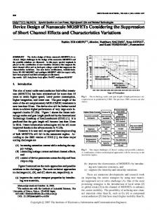
Figure 50 shows the stress cube for the straight back support bar at location (joint I).The bar is in tension as indicated by the z direction stress as a result of the angled bar. The von mises stress will be equivalent to the z direction stress. Link 3 (parallel links) will only have Y direction forces at joint locations C1. The whole link will not have any Z direction forces. Joint locations E1, E2, D1, and D2 will have X and Y forces as seen in the free body diagram in (figure 51) on page 59. The left side of link 3 in the Z-Y plane shows compressive forces from the chair and base links at joint locations (C1 and D1) on page 60 in (figure 52). The actuator will exert X and Y direction forces on link 3 at locations (E1 and E2). Joint location (D2) will pull on the base link due to the force from the user. The results will change over time. The results are in appendix C in table 7 on page 100. 58
C2
C1
E1 E2
Y
D2
D1 Z
X
Figure 51: Assembled isometric view of link 3
59
Figure 52: Free body diagram (X-Y) plane view of the link 3 (main link)
60
Figure 53: Free body diagram (Z-Y) plane view of the link 3 (main link)
61
Figure 54: Stress on the kinematic link 3 von mises stress equation.
Figure 54 shows the stress cube at location A in tension from the actuator forces and chair causing the link to bend. The results are in table 15 on page 105. The actuator forces and stress will be discussed on page 67. The other stress cubes represent the shearing stress from the chair at C, the actuator at E, and the pin joins at D. point E on the figure above will experience the highest shear stress from the actuator pin joint. The shear stress is 4617.5 psi., which was taken into consideration when the material was chosen to maintain a safety factor of 3.
62
A
D2 1 D1 F
Figure 55: isometric view of the base link
The base link will have resulting forces from link 3 and links 5 and 6 (The actuator). The free body diagram for the base is seen in (figure 56). The results of the base link forces are in table 8 on page 101.
63
Figure 56: Free body diagram of kinematic link 1 in the X-Y plane
64
65
The base link is shown with stresses at 6 locations. D1 and D2 are collinear pin joints in shear while A is the bolt underneath the base in tension and shear depend on the position of the chair. Point F stress also depends on position. The magnitudes of the forces are in table 17.the base link will experience the largest von mises stress as seen in table 17.
Figure 57: Stress on the base link 1 and the von mises stress equation. The shear stress equation is also in the figure.
Figure 58: Free body diagram of the front wheels in the X-Y plane
Figure 58 shows the wheel of the front link base free body diagram.
66
J
2 G
1
G E2
Z
1 2 3
3
Y
E1
X
F
Actuator holder Actuator cylinder Actuator piston
Figure 59: Exploded view of the actuator and holder
The actuator forces were calculated as a result of the position analysis and force analysis of link 3. The forces that the linear actuator will need to raise and lower the user in and out of the water will change over each position as cited earlier from the kinematic analysis. The free body diagram for the actuator cylinder and piston are seen on page 60 in (figure 60). The results of the forces for the free body diagram in figure 60 are in table 9 in appendix C on page 100.
67
Figure 60: Actuator Assembly Free body diagrams in the X-Y plane.
Figure 60 indicates the magnitude of the forces on each of the components of the actuator assembly. The forces on the actuator are directly related to the position and force analysis of link 3 over 20 positions. The position of joints E1 and E2 will change over each position changing the forces to keep link 3 in equilibrium with the applied load of the user. The force analysis of link 3 at position 20, as seen in the appendix C results in table 7, show that there is a significant increase in force required to support the chair. The last position is indicated in red. The last position will increase the magnitude of force along the actuator by approximately 400 lbs. The design will be altered so that link 3 never reaches that position. This alteration will keep the forces low on the actuator and would decrease the cost of the actuator needed to lift and lower the chair in and out of the water. Removing this position will result in the stroke length of the actuator. The results of the forces on the actuator are in appendix C in table 7.
68
Figure 61: Stress on the Actuator holder and the von mises stress equation. The shear stress equation is also in the figure.
Figure 61 (actuator holder) shows the stress cubes for points A and E. Point A is in compression while Points E1 and E2 are both in shear with link 3 (main link). The stress results are in table 16 in appendix D.
69
Figure 62: Stress on the Actuator kinematic links 5 and 6 and the von mises stress equation. The shear stress equation is also in the figure.
Figure 43 (actuator cylinder and piston)shows the stress cubes for points J and F. Point J is in shear while Point F are both in shear with link 1 (base link). The stress results are in table 16. The base link will exert forces on the square rods that connect the base to the counterweights that keep the entire device from overturning.
70
B
Y
D2
Z Y
X
F
D1
B
Figure 63: link 1 base in an isometric view to show the supporting bar underneath the base link
B Y X
F
D
Figure 64: x-y plane view of the tank and the wheel
71
Figure 65: Free body diagram of the square supporting rods in the X-Y plane
The following free body diagram shows the forces on the L shaped bracket and the counterweight wheels. The results of the forces on the base bar are in table 10 in appendix C on page 103.
72
Figure 66: Stress on the base bar under link 1 and the von mises stress equation. The shear stress equation is also in the figure.
Figure 66 shows the stresses on the base bar under base 1. Point A is collinear. A1 represents bar in compression while A2 and A3 represent the shearing of the bolt. The results of the stresses are in table 18 in appendix D.
73
Figure 67: Free body diagrams for the l shaped bar supporting the counterweight tanks and wheel free body diagram in the X-Y plane.
The tank bar and wheel support the counterweight and attach to the device. The results of the forces on the tank bar are in table 11 in appendix C on page 104.
74
Figure 68: stresses on the tank base with the von mises equation and shear stress equations.
The tank base stress are represented above I figure 68. Point A is collinear and will be in compression from the counterweight and base link 1. It is also in shear due to the force shearing the bolt to keep it together. The results of the stresses are in table 19 in appendix D. The second case assumption is: the load from the user is shared between the fixed bar and the upper rod. The result would be a transfer of forces through the angled bar to the straight back support piece back to the rod.
75
Results Final result
Y Z
X
X
Figure 69: The image above shows the Final result after the design had been iterated numbers times.
The device is now reflective of the materials list below. The bar and rods are represented by the joints and kinematic links in the previous figures. Chair Bar
Chair Rod C
Corrosion-Resistant HighStrength Aluminum (Alloy 7075) Alloy 20 stainless steel
Chair Bolt H
Black-Oxide 18-8 Stainless Steel
Chair Back Angle Bar Chair Back Bar Bolt I
Multipurpose Aluminum (Alloy 6061) Black-Oxide 18-8 Stainless Steel
76
Yield Strength of 56,000 psi Tensile strength of 80,000psi Tensile strength of 70,000 psi Yield Strength of 35,000 psi Tensile strength of 70,000 psi
Chair Back Straight Bar Main Link
Main Link Pin E
Multipurpose Aluminum (Alloy 6061) Corrosion-Resistant HighStrength Aluminum (Alloy 7075) Black-Oxide 18-8 Stainless Steel
Main Link Pin D
Black-Oxide 18-8 Stainless Steel
Actuator Holder
Multipurpose Aluminum (Alloy 6061) Alloy 20 stainless steel
Actuator Holder Rod J Actuator Holder Pin E
Black-Oxide 18-8 Stainless Steel
Base Link
Corrosion-Resistant HighStrength Aluminum (Alloy 7075) Black-Oxide 18-8 Stainless Steel
Base Link Bolt F
Base Bar Base Bolt 6x
Tank Bar Tank Bolt 8x
Multipurpose Aluminum (Alloy 6061) Black-Oxide 18-8 Stainless Steel Multipurpose Aluminum (Alloy 6061) Black-Oxide 18-8 Stainless Steel
Figure70: Materials list for each part
77
Yield Strength of 35,000 psi Yield Strength of 56,000 psi Tensile strength of 70,000 psi Tensile strength of 70,000 psi Yield Strength of 35,000 psi Tensile strength of 80,000psi Tensile strength of 70,000 psi Yield Strength of 56,000 psi Tensile strength of 70,000 psi Yield Strength of 35,000 psi Tensile strength of 70,000 psi Yield Strength of 35,000 psi Tensile strength of 70,000 psi
Half-Size Physical Model
Figure 71: The half-size physical model of the pool lift device.
Figure 71 shows an approximate half-size physical model of the device the team constructed using pieces from several erector sets. The model was created from half sized dimensions of the model created in solid works. The model was able to achieve a depth proportional to the full size model of approximately 9 inches. The ADA indicates a depth of 18 inches below to the water line in the pool to be ADA compliant. The only items missing from the model are the counterweight tanks to keep the device from overturning. For the demonstration books were used to keep the model from overturning. In order to demonstrate the electronic linear actuator used in the full size design PVC piping was used in combination with erector set pieces. When testing the physical model, the base and the actuator were things that stood out. The actuator could potentially rotate when fully retracted. The actuator on this model may have rotated due to the design and the fact that the physical model does not have an actual linear actuator. The base would appear to need more support where the base bars connect the base link to the counterweight base. The links at that location where the bars connect to the counter weight would bulge implying high stress and forces. The wheels in the center would have a tendency to lift off of the ground if the counterweight was not sufficient. This could be due to the cross sectional area of the erector set links as well.
78
Conclusion The goal of this project was to create a device that lifts and lowers a human safely in and out the pool. The outcome of this project created a working design of a device that achieves the desired kinematics and positions for the chair as set forth by the ADA. The design was created using 3 position syntheses from the design of machinery book from Professor Robert Norton. The three position synthesis created a four bar linkage. After numerous iterations of the design the links were curved to allow the chair to reach the desired depth set forth from the ADA standards. When the linkage system was created it was decided that an electric linear actuator would be used to raise and lower the links to allow the chair to move through the desired positions. Conducting the position analysis for the system revealed the ideal location of the actuator and the transmission angles. The angles range from 73-110 degrees. From the position analysis of the linkage system the force analysis was conducted at 20 locations. Based on the iteration of this design and benchmarking of similar devices the team set out to keep the force required from the actuator low. The first 19 positions keep the forces required from the actuator below 1000 lbs. of force but at position 20 would show a significant increase. Following the force analysis the stress analysis was done. The physical model that was created revealed that the forces and stresses in the base link may be significantly large in the full size model. The bars underneath the base will take a significant amount of force. A redesign of the base may be required to add support to increase the safety of the device.
79
Future work/recommendations
Recommendation
Description
Redesign of the chair to increase aesthetics.
The chair could use a foot rest, handles, or an armrest to increase the comfort of the user. The chair could also include cushions. The chair could also be made to fold to make the device more compact. To ensure the device will not fail, further analysis of the device should be conducted. Further analysis including the materials chosen for this design to ensure the parts will not fail. A redesign of the base may be necessary to reduce the forces and stresses by adding supports, changing the cross section of the parts or selecting other materials. The cross sections of the curved links are rectangular. The links could be redesign with shapes of their cross section to compare against the square bar cross sectional shape. The current design uses rectangular plastic tanks. The shape of the cross section could be redesigned to change the floor space the device occupies. Different types of counterweight could be tried as well such as sand water, or free weights. The design of the actuator in this design is based off of a specific type of actuator sold on the market. As a warning: Using a different type may change the kinematics and position analysis of the design as well as how the actuator holder fits the current actuator. Benchmarking revealed that each company uses certain of linear actuator to lift the chair. Some work could be done on using different types of motors. A remote for operating the lift could be devised as well as other parts.
Check the parts and analysis
Base Support
Try different cross sections for the link. The counter weight could be redesigned
The actuator for the device could be changed
Try lifting the chair with another type of motor. Add waterproofed electrical components.
80
Resources "Aqua Creek: Lifts." Aqua Creek: Lifts. Aqua Creek Products, n.d. Web. 09 Dec. 2012. . Hibbeler, R.C. Statics and Mechanics of Materials, second edition.1993, Prentice Hall Norton, Robert. Design Of Machinery: An Introduction to the Synthesis and Analysis of Mechanisms and Machines, Fifth edition. 2012, McGraw-Hill Companies. Pearson Education. Norton, Robert. Machine Design: An Integrated Approach, Fourth Edition. 2011, McGraw-Hill Companies. "Spectrum Aquatics - Missoula, MT." Traveler II XRC500 ADA Pool Lift. Spectrum Aquatics, n.d. Web. 09 Dec. 2012. .
81
Appendix A The Design Chart The Design Chart below illustrates the 5 preliminary designs that were evaluated toward the beginning of the project. Each design was more of a concept when they were evaluated. The weighing factors for the chart were chosen by team based on what would seem most important at the time. Safety is the most important factor but from an economic stand point cost gets the edge with the highest weighing factor. The project is centered on cost and safety. Reliability had the lowest weighing factor as a result of the other weighing factors having a greater importance at the time. The teams’ ability to analyze each design decided the weighing factor for analysis. Transfer and kinematics tied for the second least weighing factor due to the fact that once the user has been loaded into the chair the steps for transferring the user into the water and the type of motion involved did not seem as critical as the safety and cost. Power was based on the need for assistance by the user. Once the project moved forward it was understood that the user would need to be able to operate the device without outside assistance in order to be ADA compliant. The rack chain/ elevator and the arm swing were eliminated early in the project. Though the chart would indicate that the rack chain was the best concept the team was unable to excel on that design and chose to focus on the straight line linkage. Once, the team was convinced that the straight line linkage that had been designed would not work as planned the team tried to create the device using a scissor lift. The lift is in the preliminary design section of this report but was not designed early on when the design chart was created. Once the force calculations force the scissors lift were done the team went for the four bar concept. Designs
Safety Cost Reliability Analysis Transfer Power
Kinematic Rank
Weight Factor
0.2
0.25 0.05
0.15
0.1
0.15
0.1
1
Design 1
Four Bar
4
4
5
5
4
3
2
3.85
Design 2
Six bar
4
4
5
4
4
3
3
3.8
Design 3
Rack Chain/Elevator 5
3
4
5
4
5
5
4.35
Design 4
Arm Swing
2
5
5
4
4
3
5
3.85
Design 5
Pulley Cable
3
3
5
4
4
4
5
3.7
82
Safety - The mechanism must never tip over at any position and keep the patient steady at all times. The process by which the patient is transferred into the water must safe and must not expose the patient harsh sudden movements.
5 – Very safe transfer and movements, and no tipping 4 – Safe transfer and less desirable movements, and tipping 3 – Less safe transfer and even less desirable movements, and tipping 2 – Acceptable level of safety and movements, and tipping 1 – Unacceptable level of safety, and movements, and tipping
Easy Assembly - The mechanism must be able to be assembled in 15 minutes. 5 - The mechanism can be assembled in 5 minute. 4 - The mechanism can be assembled in 10 minute. 3 - The mechanism can be assembled in 15 minute. 2 - The mechanism can be assembled in 20 minute. 1 - The mechanism can be assembled in more than 20 minute.
Complexity - The mechanism is designed to be assembled with least parts and as simple as possible. 5 – The mechanism has 2 parts. 4 - The mechanism has 3 parts. 3 - The mechanism has 4 parts. 2 - The mechanism has 5 parts. 1 - The mechanism has 6 or more parts.
Cost - The cost of the mechanism including manufacturing cost and product price.
83
5 - The cost of the mechanism is under $600. 4 - The cost of the mechanism is under $900. 3 - The cost of the mechanism is under $1200. 2 - The cost of the mechanism is under $1500. 1 - The cost of the mechanism is over $1500.
Reliability - The mechanism must be easy to repair and maintain. 5 - The reparation and maintenance of the mechanism are simple which can be done by the customer with manual. 4 - The reparation and maintenance of the mechanism will take some time by the customer with manual or simple if call specialist. 3 - The reparation and maintenance of the mechanism is not complex but must be done by specialist. 2 - The reparation and maintenance of the mechanism is complex and must be done by specialist. 1 - The reparation and maintenance of the mechanism is very complex and must be done by specialist.
Analysis - The mechanism must be easy to analysis with basic equations, and also capable with computer software. 5 - The analysis of the mechanism uses basic equations and does not require computer software. 4 - The analysis of the mechanism uses advance equations and does not require computer software. 3 - The analysis of the mechanism uses basic equations and requires computer software. The mechanism is capable to computer software. 2 - The analysis of the mechanism uses advance equations and requires computer software. The mechanism is capable to computer software. 1 - The analysis of the mechanism uses advance equations and not capable to computer software.
84
User friendly – The mechanism is easy to understand. 5 - The mechanism is easy to use that doesn't need a manual. 4 - The mechanism is easy to use after the user read the manual. 3 - The mechanism takes time to get familiar with after the user follow the manual several times. 2 - The mechanism is complicated and may cause confusions. 1 - The mechanism is hard to understand.
Manually Self-operational – The mechanism must be able to self-operate by the patient without assistant and any kind of electronic parts. The mechanism can have extra mechanical parts to achieve manual self-operation. 5 – The mechanism can self-operate and use minimum 1 manual power method. 4 – The mechanism can self-operate and use minimum 2 manual power methods. 3 - The mechanism can self-operate and use minimum 3 manual power methods. 2 – The mechanism can self-operate and use minimum 4 or manual power methods. 1 – The mechanism can't self-operate without any kind of electronic parts.
Transfer - The transfer steps for the mechanism should be as less as possible. This is the number of steps to the water once the patient is loaded into the chair. 5 – One step process 4 – Two step process 3 – Four or Three step process 2 – Five or six step process 1 – Seven or more step process
Kinematic - The motion of the mechanism must be simple, straight movements are preferred. 5 - The motion only contains horizontal and vertical movements. 85
4 - The motion contains mainly horizontal and vertical and some curve movements. 3 - The motion contains mainly curve movements and some horizontal and vertical movements. 2 - The motion contains only curve movements. 1 - The motion contains horizontal, vertical, curve and other movements.
Power -.The mechanism is ideally man powered (non electric) and self operational. This is a measure of the ability. 5 - The mechanism requires only the patient and no outside assistance for operation. 4 - The mechanism requires the patient and outside (non electric) assistance for operation. 3 - The mechanism requires an assistant and no electric motors for operation. 2 - The mechanism requires an assistant and an electric motor for operation. 1 - The mechanism requires solely electric motor(s) for operation.
86
Appendix B Position analysis
Y X
Figure 72: (X-Y) plane view (Side view) of the design with the actuator fully extended.
Each of the following images show the 20 positions used in the position analysis. Link 6 is omitted from each drawing but will maintain its length and will be collinear with link 5 through each step. Table 4 on page 98 shows each change and stroke length affects the transmission angle.
87
88
Figure 73: positions 1-2 show the linear actuator (link 5) moving from a stroke length of 20.39 in. as seen on the left to 19 in. as seen on the right.
89 Figure 74: positions 3-4 show the linear actuator (link 5) moving from a stroke length of 18 in. as seen on the left to 17 in. as seen on the right.
90
Figure 75: positions 5-6 show the linear actuator (link 5) moving from a stroke length of 16 in. as seen on the left to 15 in. as seen on the right.
91
Figure 76: positions 7-8 show the linear actuator (link 5) moving from a stroke length of 14 in. as seen on the left to 13 in. as seen on the right
92
Figure 77: positions 9-10 show the linear actuator (link 5) moving from a stroke length of 12 in. as seen on the left to 11 in. as seen on the right.
93
Figure 78: positions 11-12 show the linear actuator (link 5) moving from a stroke length of 10 in. as seen on the left to 9 in. as seen on the right.
94
Figure 79: positions 13-14 show the linear actuator (link 5) moving from a stroke length of 8 in. as seen on the left to 7 in. as seen on the right
95
Figure 80: positions 15-16 show the linear actuator (link 5) moving from a stroke length of 6 in. as seen on the left to 5 in. as seen on the right.
96
Figure 81: positions 17-18 show the linear actuator (link 5) moving from a stroke length of 4 in. as seen on the left to 3 in. as seen on the right.
97
Figure 82: positions 19-20 show the linear actuator (link 5) moving from a stroke length of 2 in. as seen on the left to 1.47 in. as seen on the right.
Table 4: Stroke Length vs. Transmission Angle
Stroke Transmission Length(in.) Angle 20.39 73.71 19 79.68 18 83.39 17 86.78 16 89.89 15 92.8 14 95.51 13 98.05 12 100.42 11 102.63 10 104.65 9 106.48 8 108.04 7 109.28 6 110.04 5 110.06 4 108.78 3 104.8 2 93.11 1.47 74.35
98
Appendix C Force analysis Excel Data Table 3: Counter Weight (x-y) plane force results
Fw(lbs.) a(in.) b(in.) Fcounter(lbs.) 300 18.54 23.47 236.983
Table 4: Counter Weight (y-z) force results
Fw(lbs.) a(in.) b(in.) Fcounter(lbs.) 300 4.19 7.62 164.960
Table 5: Chair Bar (x-y) force results
Fw(lbs.) F2y(lbs.) 300 300
Table 6: Chair Bar (y-z) force results
Fw(lbs.) a(in.) b(in.) F2y(lbs.) F2z(lbs.) F1z(lbs.) 300 8.75 13 300 201.9231 201.923
Table 7: Chair Back Angle Bar (y-z) force results
F1z(lbs.) a(in.) Mi(lbs.-in.) 201.9231 6.3 1272.115
Table 8: Chair Back Straight Bar (y-z) results
F2z(lbs.) F1z(lbs.) F3z(lbs.) 201.923 201.923 0
99
100
Stroke Factuator α Length Fay (inch) F2x (lbs) F2y (lbs) θ(Degree) θ(Radian) (Degree) α (Radian) a (inch) b (inch) c (inch) d (inch) (Joint E) (lbs) Fax 84.7134 98.460 6.54 0.2505 28.8 10.39 1.84 14.35 1.286 73.71 300 0 20.39 -164.8058 -207.984 4.06 0.4760 28.48 11.59 -4.65 27.27 1.391 79.68 300 0 19 -261.1315 -351.498 2.37 0.6180 27.53 12.05 -8.63 35.41 1.455 83.39 300 0 18 -318.6497 -459.712 0.78 0.7487 26.17 12.25 -12.15 42.9 1.515 86.78 300 0 17 -348.7477 -542.668 0.8709 24.5 12.26 -15.25 -0.72 49.9 1.569 89.89 300 0 16 -359.5719 -607.805 0.9866 22.57 12.09 -17.97 -2.13 56.53 1.620 92.8 300 0 15 -355.8827 -659.287 1.0968 20.46 11.79 -20.35 -3.44 62.84 1.667 95.51 300 0 14 -340.4254 -699.323 1.2029 18.19 11.36 -22.4 -4.67 68.92 1.711 98.05 300 0 13 -315.9037 -730.050 1.3052 15.81 10.82 -24.14 -5.81 74.78 1.753 100.42 300 0 12 -284.1505 -753.650 1.4046 13.33 10.19 -25.59 -6.85 80.48 1.791 102.63 300 0 11 -245.7033 -769.929 9.48 -26.76 -7.81 1.5017 10.79 86.04 1.826 104.65 300 0 10 -202.2322 -781.365 8.69 -27.67 -8.67 8.2 1.5966 91.48 1.858 106.48 300 0 9 -153.0771 -787.411 7.85 -28.31 -9.44 1.6900 5.59 96.83 1.886 108.04 300 0 8 -98.4267 -788.589 6.95 -28.7 -10.13 1.7822 2.96 1.907 102.11 109.28 300 0 7 -37.0970 -787.515 5.99 -28.85 -10.72 1.8734 0.33 1.921 107.34 110.04 300 0 6 34.1009 -784.922 5 -28.76 -11.22 1.9644 -2.29 1.921 112.55 110.06 300 0 5 122.9464 -785.064 3.95 -28.44 -11.63 2.0558 -4.91 1.899 117.79 108.78 300 0 4 252.0528 -800.623 2.85 -27.85 -11.94 2.1494 -7.54 1.829 123.15 104.8 300 0 3 531.1190 -906.645 1.62 -26.94 -12.17 2.2510 -10.33 1.625 128.97 93.11 300 0 2 1170.0699 -1370.389 0.77 -26.15 -12.26 2.3209 -12.19 1.298 132.98 74.35 300 0 1.47
Table 9: Main Link (x-y) (Kinematic link 3) force results
50.179 -126.872 -235.289 -331.357 -415.769 -490.035 -554.983 -610.871 -658.162 -698.030 -729.671 -754.741 -772.388 -782.422 -786.641 -784.180 -775.377 -759.912 -734.792 -713.373
F4 (Joint D) (lbs) F4y (lbs) F4x (lbs) 360.280 350.179 84.713 239.028 173.128 -164.806 269.030 64.711 -261.132 320.189 -31.357 -318.650 367.461 -115.769 -348.748 406.701 -190.035 -359.572 437.800 -254.983 -355.883 461.010 -310.871 -340.425 477.572 -358.162 -315.904 489.050 -398.030 -284.150 494.962 -429.671 -245.703 497.682 -454.741 -202.232 496.571 -472.388 -153.077 492.360 -482.422 -98.427 488.053 -486.641 -37.097 485.380 -484.180 34.101 491.019 -475.377 122.946 524.452 -459.912 252.053 686.390 -434.792 531.119 1240.944 -413.373 1170.070
Table 10: Base Link (x-y) force results
Factuator (Joint E) φ φ (lbs) F4x (lbs) F4y (lbs) (degree) (radian) a 98.460 84.713 350.179 30.63 0.535 -207.984 -164.806 173.128 37.59 0.656 -351.498 -261.132 64.711 42.01 0.733 -459.712 -318.650 -31.357 46.12 0.805 -542.668 -348.748 -115.769 50.01 0.873 -607.805 -359.572 -190.035 53.73 0.938 -659.287 -355.883 -254.983 57.34 1.001 -699.323 -340.425 -310.871 60.87 1.062 -730.050 -315.904 -358.162 64.36 1.123 -753.650 -284.150 -398.030 67.85 1.184 -769.929 -245.703 -429.671 71.39 1.246 -781.365 -202.232 -454.741 75.01 1.309 -787.411 -153.077 -472.388 78.79 1.375 -788.589 -98.427 -482.422 82.83 1.446 -787.515 -37.097 -486.641 87.3 1.524 -784.922 34.101 -484.180 92.49 1.614 -785.064 122.946 -475.377 99.01 1.728 -800.623 252.053 -459.912 108.35 1.891 -906.645 531.119 -434.792 125.86 2.197 -1370.389 1170.070 -413.373 148.64 2.594
d 5.5 5.5 5.5 5.5 5.5 5.5 5.5 5.5 5.5 5.5 5.5 5.5 5.5 5.5 5.5 5.5 5.5 5.5 5.5 5.5
b 5.5 5.5 5.5 5.5 5.5 5.5 5.5 5.5 5.5 5.5 5.5 5.5 5.5 5.5 5.5 5.5 5.5 5.5 5.5 5.5
101
c 5.09 5.09 5.09 5.09 5.09 5.09 5.09 5.09 5.09 5.09 5.09 5.09 5.09 5.09 5.09 5.09 5.09 5.09 5.09 5.09
e 5.91 5.91 5.91 5.91 5.91 5.91 5.91 5.91 5.91 5.91 5.91 5.91 5.91 5.91 5.91 5.91 5.91 5.91 5.91 5.91
F5y F6x F7y 1.5 362.102 169.436 62.0869 1.5 116.999 -329.612 -183.001 1.5 -17.692 -522.304 -317.647 1.5 -129.444 -637.299 -429.444 1.5 -222.063 -697.495 -522.063 1.5 -299.282 -719.144 -599.282 1.5 -363.213 -711.669 -663.275 1.5 -414.896 -680.851 -714.896 1.5 -455.500 -631.807 -755.5 1.5 -486.708 -568.301 -786.708 1.5 -507.863 -491.407 -807.863 1.5 -521.060 -404.333 -821.095 1.5 -525.318 -306.154 -825.318 1.5 -520.447 -196.853 -820.447 1.5 -507.940 -74.194 -807.94 1.5 -486.062 68.202 -786.062 1.5 -453.028 245.893 -753.028 1.5 -402.352 504.106 -702.352 1.5 -301.123 1062.238 -601.123 1.5 -105.420 2340.264 -405.216
Table 11: Base Link Wheel (x-y) force results
F7y(lbs.) Fwheel(lbs.) 62.0869 62.0869 183.001 -183.001 317.647 -317.647 429.444 -429.444 522.063 -522.063 599.282 -599.282 663.275 -663.275 714.896 -714.896 -755.5 -755.5 786.708 -786.708 807.863 -807.863 821.095 -821.095 825.318 -825.318 820.447 -820.447 -807.94 -807.94 786.062 -786.062 753.028 -753.028 702.352 -702.352 601.123 -601.123 405.216 -405.216
102
Table 12: Base Bar (x-y) force results
F5y(lbs.) F6x(lbs.) F7y(lbs.) a(in.) b(in.) c(in.) F9y(lbs.) 362.1017 169.4355 62.0869 5.5 5.5 9.5 245.5829 116.9994 -329.612 183.001 5.5 5.5 9.5 -38.2112 -17.6924 -522.304 317.647 5.5 5.5 9.5 -194.144 -129.444 -637.299 429.444 5.5 5.5 9.5 -323.566 -222.063 -697.495 522.063 5.5 5.5 9.5 -430.81 -299.282 -719.144 599.282 5.5 5.5 9.5 -520.222 -363.213 -711.669 663.275 5.5 5.5 9.5 -594.283 -414.896 -680.851 714.896 5.5 5.5 9.5 -654.09 -455.5 -631.807 -755.5 5.5 5.5 9.5 -701.105 -486.708 -568.301 786.708 5.5 5.5 9.5 -737.24 -507.863 -491.407 807.863 5.5 5.5 9.5 -761.736 -521.06 -404.333 821.095 5.5 5.5 9.5 -777.037 -525.318 -306.154 825.318 5.5 5.5 9.5 -781.948 -520.447 -196.853 820.447 5.5 5.5 9.5 -776.308 -507.94 -74.1941 -807.94 5.5 5.5 9.5 -761.825 -486.062 68.20187 786.062 5.5 5.5 9.5 -736.493 -453.028 245.8929 753.028 5.5 5.5 9.5 -698.243 -402.352 504.1056 702.352 5.5 5.5 9.5 -639.566 -301.123 1062.238 601.123 5.5 5.5 9.5 -522.353 -105.42 2340.264 405.216 5.5 5.5 9.5 -295.632
103
F8x(lbs.) 169.4355 -329.612 -522.304 -637.299 -697.495 -719.144 -711.669 -680.851 -631.807 -568.301 -491.407 -404.333 -306.154 -196.853 -74.1941 68.20187 245.8929 504.1056 1062.238 2340.264
Table 13: Tank Bar (x-y) force results
F9y(lbs.) F8x(lbs.) Fcounter(lbs.) F10y(lbs.) F10x(lbs.) 245.583 169.436 236.983 482.566 169.436 -38.211 -329.612 198.772 -329.612 -194.144 -522.304 42.84 -522.304 -323.566 -637.299 -86.583 -637.299 -430.81 -697.495 -193.827 -697.495 -520.222 -719.144 -283.238 -719.144 -594.283 -711.669 -357.299 -711.669 -654.09 -680.851 -417.107 -680.851 -701.105 -631.807 -464.121 -631.807 -737.24 -568.301 -500.257 -568.301 -761.736 -491.407 -524.753 -491.407 -777.037 -404.333 -540.054 -404.333 -781.948 -306.154 -544.964 -306.154 -776.308 -196.853 -539.324 -196.853 -761.825 -74.194 -524.842 -74.1941 -736.493 68.202 -499.509 68.2027 -698.243 245.893 -461.26 245.893 -639.566 504.106 -402.582 504.105 -522.353 1062.238 -285.369 1062.238 -295.632 2340.264 -58.6482 2340.264
104
Appendix D Stress Analysis Excel Data Table 14: Chair Bar Stresses
Chair Bar Body Ma(lbs.Fw(lbs.) F2y(lbs.) F2z(lbs.) a(in.) in.) b(in.) h(in.) I(in.) σy(psi) σz(psi) σ'(psi) 300 300 201.9231 8.1 2430 1 1 0.083 300 14580 14432.34 Point C at bar τC at bar Rrod(in.) Arod(in.^2) (psi) 0.25 0.196 763.9437 Point C at Rod τC at rod Rrod(in.) Arod(in.^2) (psi) σz(psi) σ'(psi) 0.25 0.196 1527.887 807.6923 2707.306 Point H at bar τH at bar Rpin(in.) Apin(in.^2) (psi) 0.125 0.049 3055.775 Point H at Pin τH at pin Rpin(in.) Apin(in.^2) (psi) σz(psi) 0.125 0.049 6111.55 1615.385 10646.96
Table 15: Chair Back Angle Bar Stresses
Mi(lbs.F1z(lbs.) in.) b(in.) h(in.) 201.923 1272.115 1
I(in.) σz(psi) σ'(psi) 1 0.0833 7632.692 5397.128
Dpin(in.) b(in.) h(in.) Ipin Ibar Isum σz(psi) σ'(psi) 0.25 0.2 0.7 0.0001 0.006 0.006 26913.21 19030.52
Table 16: Chair Back Straight Bar Stresses
Mi(lbs.in.) b(in.) h(in.) I(in.) σz(psi) σ'(psi) 1272.115 1 1 0.0833 7632.692 5397.128
105
Table 17: Main Link Stresses (Kinematic link 3)
F4x (lbs) F4y (lbs) a(in.) c(in.) b(in.) h(in.) I(in.) σx(psi) σy(psi) σ'(psi) 84.7134 350.1792 8.45 7.04 0.5 1 0.041667 8589.937 29583.14 26359.66 Table 18: Actuator Holder Stresses
Factuator (Joint E) (lbs) b(in.) 906.6454197 Point E at bar Rpin(in.)
h(in.) 4.1
1.96
Aplate(in.^2) σtensile(psi) 8.036
-112.823
Apin(in.^2) τC(psi)
0.25 0.19635 2308.75 Point E at Rod Rpin(in.) Apin(in.^2) τC(psi) 0.25 0.19635 4617.51
Table 19: Base Link Stresses
Factuator F4 (Joint D) (Joint E) (lbs) (lbs) 906.6454197 686.389838 Point D at bar Rpin(in.) Apin(in.^2) 0.25 0.19634954 Point D at Rod Rpin(in.) Apin(in.^2) 0.25 0.19634954
ΤD 1747.877 τD 3495.755
Point F at bar Rpin(in.) Apin(in.^2) ΤF 0.25 0.19634954 -2308.75 Point F at Rod Rpin(in.) Apin(in.^2) τF 0.25 0.19634954 -4617.51 F6x(lbs)
M6x(lbs.-in.)
b(in.)
h(in.)
I(in.) 106
σy(psi)
Dpin(in.) Apin(in.^2) τ6x (psi)
σ' (psi)
1062.237919
-7305.5018
14
0.5 0.145833
12523.7
0.25
0.049087
21639.73 38513.06
Table 20: Base Bar Stresses
M6x(lbs.F9y(lbs) F6x(lbs) in.) b(in.) h(in.) I(in.) σy(psi) σ'(psi) 781.948 1062.238 -7428.5 16.75 0.5 0.174479 10643.8 8865.44 Point 6x at bar Rpin(in.) Apin(in.^2) 0.25 0.19635 Point 6x at pin Rpin(in.) Apin(in.^2) 0.25 0.19635
τ6x(psi) 2704.967 τ6x(psi) 5409.933
Table 21: Tank Bar Stresses
M10x(lbs.F9y(lbs) F10x(lbs) a(in.) in.) b(in.) h(in.) I(in.) σy (psi) σ' (psi) 781.948 1062.238 0.94 -735.031 2.5 0.5 0.026042 7056.29 6844.427 Point 10x at bar Rpin(in.) Apin(in.^2) 0.25 0.19635 Point 10x at pin Rpin(in.) Apin(in.^2) 0.25 0.19635
τ10x 2704.967 τ10x 5409.933
107