design of the roll controller on an experimental setup through the stages of data ... bottom up. For this purpose we built a custom quadrotor hardware and ...
International Journal of Materials, Mechanics and Manufacturing, Vol. 1, No. 4, November 2013
Design of a Quadrotor Roll Controller Using System Identification to Improve Empirical Results Anil Ufuk Batmaz, Ovunc Elbir, and Cosku Kasnakoglu Abstract—Unmanned Aerial Vehicles (UAVs), specifically quadrotors, is one of the major topics of study in current literature with applications to numerous fields. In this paper we consider a test-bed for the design of a low cost flight controller for a quadrotor and as a first step in design we demonstrate the design of the roll controller on an experimental setup through the stages of data collection, modeling, control design and verification. The procedure consists of four stages: 1) Experimental determination of controller coefficients, 2) Data collection, 3) System identification, 4) Controller redesign by tuning coefficients with a numerical search. It is observed that the system designed as such is capable of achieving the desired roll stabilization, and coefficient tuning on the identified model noticeably improves the settling time and steady state oscillation amplitude.
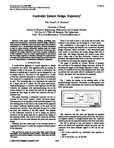
II. METHODOLOGY The basic quadrotor model used in the study is shown in Fig. 1. F1 , F2 , F3 and F4 are the forces applied by the servomotors, as result of which the pitch (𝜃), roll (𝜙) and yaw angle (𝜓) of the quadrotor are produced.
Fig. 1. Simple Quadrotor Model
Index Terms—Aerial vehicle control, discrete time, linear estimation, quadrotor.
III. HARDWARE DESIGN I. INTRODUCTION
The general overview of the hardware design can be seen in Fig. 2.
Unmanned Aerial Vehicles (UAVs) have recently gained great importance in both military and civil applications [1]-[5]. These designs also call for the development of various control methodologies [6]-[8]. An important subset of UAVs is quadrotors, which have become popular recently due to their small size and maneuverability. Research efforts on quadrotors include attitude stabilization, estimation and multi-vehicle configurations [9]-[11]. In the present work we attempt to demonstrate roll-axis stabilizing controller design approach on an experimental test-bed in an attempt to form a foundation for our ultimate research goals of building a unique quadrotor system from bottom up. For this purpose we built a custom quadrotor hardware and implemented software procedures to drive the servomotors, carry out measurements, communicate data, and control the attitude of the UAV, using reasonable cost and commonly available electronic components. An important contribution of this paper is to illustrate a simple process to improve empirically determined controllers so as to improve the overall closed-loop response of the system. This involves identifying a transfer function around the desired equilibrium (which is the horizontal axis for roll stabilization) and performing a numerical search using this model to tune the coefficients. The rest of the paper will explain the methodology, present experimental results and discuss the findings.
Fig. 2. General overview of the hardware design.
For the IMU we utilize Microstrain-3DM-GX2, which contains a triaxial accelerometer, triaxial gyro, triaxial magnetometer, and an on-board processor running a sensor fusion algorithm. For the communication block we implement a voltage level converter in order to map the output of the IMU into UART voltage levels. As for the microprocessor, a PIC32MX795F512L has been used which can operate up to 80 MHz. The test platform hardware is shown in Fig. 3. As mentioned previously, for the sake of example we shall only consider the stabilization of the roll angle 𝜙; hence, the quadrotor has been fixed in the setup to allow for rolling behavior only.
Manuscript received October 15, 2012; revised March 10, 2013. The authors are with the Department of Electrical and Electronics Engineering, TOBB ETU Ankara 06560 Turkey (e-mail: aubatmaz@ etu.edu.tr, oelbir@ etu.edu.tr, kasnakoglu@ etu.edu.tr).
DOI: 10.7763/IJMMM.2013.V1.75
Fig. 3. Experimental quadrotor test platform.
347
International Journal of Materials, Mechanics and Manufacturing, Vol. 1, No. 4, November 2013
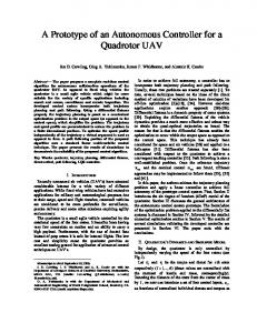
where the sampling period is 𝑇𝑠 = 0.025 s, which is the rate that we process data for our particular hardware/software configuration. One can observe a good agreement between the output measured from experiments and the output simulated from the model, which are compared in Fig. 5.
IV. SOFTWARE DESIGN The roll angle ϕ is calculated from the outputs of the IMU using the following equation ∅=
𝑎𝑦 𝑎𝑥 𝑠𝑖𝑛 𝜃 − 𝑎𝑧 𝑐𝑜𝑠 𝜃
(1)
Measured output 100
where 𝑎𝑥 , 𝑎𝑦 and 𝑎𝑧 are the accelerations read from the inertial sensors in the x, y, z axis respectively and 𝜃 = 𝑎𝑥 𝑎𝑧
. This calculated angle is then processed by a
60
Degree
𝑡𝑎𝑛 −1
80
Kalman filter so as to obtained a cleaner and more precise measurement. The process and measurement noise covariances of the filter were obtained empirically as 𝑄 = 1 and 𝑅 = 1.5. Following filtering, the measurements enter a PID controller, whose block diagram is illustrated in Fig. 4.
40 20 0 -20
0
10
20
30 Time
40
50
60
(a)
Fig. 4. Block diagram of the PID Controller
Note from the figure that for better numerical accuracy, the derivative term is used directly from the angular velocity measurements obtained from the IMU instead of numerically differentiating the error signal. Note also the minus sign in front of the D term since for a constant roll angle reference 𝑑err 𝑑 𝑑 we have ref − err = − err . The method we = 𝑑𝑡 𝑑𝑡 𝑑𝑡 employ in determining the PID coefficients consists of four stages: 1) Experimental determination of the PID coefficients, 2) Data collection, 3) System identification, 4) Controller redesign by tuning coefficients with a numerical search. For the first stage we run the experimental setup and use heuristic rules of thumb, such as slowly increasing P until the system somewhat oscillates around the horizontal, then adding a D term to reduce oscillations and finally adding an I term to eliminate the steady state error. The values resulting from this procedure are 𝐾𝑝 = 0.5, 𝐾𝑖 = 0.001 and 𝐾𝑑 = 0.45, which produced in a closed loop system capable of stabilizing the roll angle, but the response was slower than desired and quite jittery. For this reason we proceed with the extra tasks described below.
(b) Fig. 5. Measured output (a) and simulated model output (b).
VI. CONTROLLER REDESIGN With the model of the system at hand, we now proceed to redesign the controller so as to improve the performance of the closed loop system, in particular, the time it takes for the system to settle. For this purpose we set up a numerical search problem in MATLAB within a five percent neighborhood of the empirical coefficient values, and look for a solution that minimizes the settling time. This process yields the coefficient values 𝐾𝑝 = 0.5259, 𝐾𝑖 = 0.081 and 𝐾𝑑 = 0.53 , using which we form the discrete time PID controller
V. SYSTEM IDENTIFICATION
𝐶(𝑧) = 𝐾𝑝 + 𝐾𝑖
We perform system identification using experimental data obtained from the PID coefficients mentioned above with the goal of producing a linear model around the operating point ϕ ≈ 0. The system input is selected as the mean-shifted pulse width modulation value (PWM) that is fed to the servomotors rotating the propellers. The output is the roll angle ϕ . Numerous system identification techniques were applied to the data through the use of MATLAB System Identification Toolbox, but the best results were achieved with subspace identification (N4SID) [12]. The discretized version of this model has the transfer function 𝐺 z = 0.02526z −1 − 0.02892z −2 − 0.01516z −3 + 0.01881z −4 1 − 3.415z −1 + 4.299z −2 − 2.352z −3 + 0.4682z −4
1+𝑧 −1 𝑇𝑠 1−𝑧 −1 2
+ 𝐾𝑑
1−𝑧 −1 𝑇𝑠
(3)
where the derivation and integration in discrete time are approximated 𝑦 𝑘−1 +
as
𝑢 𝑘 +𝑢 𝑘−1 2
𝑦 𝑘 =
𝑢 𝑘 −𝑢 𝑘−1 𝑇𝑠
and
𝑦 𝑘 =
𝑇𝑠 respectively.
VII. RESULTS
Fig. 6 shows a comparison between two sets of the experimental results: the response of the closed-loop system with the empirical PID coefficients and the response of the closed-loop system with the PID coefficients tuned on the (4) model obtained from system identification. It can clearly be seen that the tuned coefficients have improved the 348
International Journal of Materials, Mechanics and Manufacturing, Vol. 1, No. 4, November 2013 [4]
W.-K. Chen, Linear Networks and Systems, Belmont, CA: Wadsworth, 1993, pp. 123-135. [5] B. Erginer and E. Altuğ, “Modeling and PD Control of a Quadrotor VTOL Vehicle,” in Proc. the 2007 IEEE Intelligent Vehicles Symposium Istanbul, Turkey, June 13-15, 2007. [6] G. Chowdhary and S. Lorenz, “Control of a VTOL UAV via Online Parameter Estimation AIAA Guidance,” presented at Navigation, and Control Conference and Exhibit, 15 - 18 August, San Francisco, California, 2005. [7] M. Ö. Efe, “Robust Low Altitude Behavior Control of a Quadrotor Rotorcraft Through Sliding Modes,” in Proc. Mediterranean Conference on Control and Automation, July 27-29, Athens , Greece, 2007. [8] P. Castillo and A. E. Dzul, “Stabilization of a mini-rotorcraft having four rotors,” in Proc. the IEEE Conference on Intelligent Robots and Systems, September 28-August 2, 2004. [9] A. Tayebi and S. McGilvray, “Attitude Stabilization of a VTOL Quadrotor Aircraft,” IEEE Transactions on Control Systems Technology, vol. 14, no. 3, May 2006. [10] M. Valenti, B. Bethke, G. Fiore, J. P. How, and E. Feron, “Indoor multivehicle flight testbed for fault detection, isolation, and recovery,” presented at AIAA Guidance, Navigation, and Control Conference, Keystone, 2006. [11] M. G. Earl and R. D'Andrea, “Real-time Attitude Estimation Techniques Applied to a Four Rotor Helicopter,” in Proc. 43rd IEEE Conference on Decision and Control, 2004. [12] P. Van Overschee and B. De Moor, Subspace identification for linear systems: Theory-Implementation-Applications, Kluwer Academic Publishers, Dordrecht, 1996.
closed-loop response significantly; the roll angle settles much faster, and once amplitude of the steady state oscillations are lower. VIII. CONCLUSION AND FUTURE WORK This paper presented a quadrotor roll axis control system based on a PID controller. The controller was first tuned experimentally so that the response stays around the horizontal, after which mean-shifted servomotor PWM values and the roll angle readings from the IMU were stored to from an input-output data set. This set was subjected to system identification so as to produce a transfer function of the quadrotor system around the origin, and it was observed that the model can reproduce the system response quite acceptable. Using a numerical search procedure, the PID coefficients were then tuned around a local neighborhood of the empirical PID for a faster settling time. The coefficients obtained from this procedure were tested on the experimental setup and it was observed that the settling time as well as the steady state oscillations of the closed-loop system was improved. Future research directions include extending the results to the control of the pitch and yaw axis, as well as the testing of the approach presented on different air vehicles.
Anil Ufuk Batmaz was born in Ankara, Turkey on February 17, 1988. He took his B.Sc. degree from the Department of Electrical and Electronics Engineering, TOBB ETU (Ankara/Turkey) in August 2011, with area of interest including classical control theory and wireless sensor networks. Currently he is a M.Sc. student and research assistant at Department of Electrical and Electronics Engineering, TOBB ETU as well. He worked as intern engineer at R&D Department of ASELSAN Author’s formal Incorporation (September - December 2008) and TAI Incorporation photo- December 2009 and April- August 2010). (September Mr. Batmaz's research interests are linear and nonlinear control, unmanned air vehicles, dynamical modeling, wireless communication systems and wireless sensor networks.
(a)
Ovunc Elbir obtained his B.S. degree from the Department of Electrical and Electronics Engineering, TOBB ETU, Ankara, Turkey in 2010, Currently he is a M.S. student and teaching assistant at Department of Electrical and Electronics Engineering, TOBB ETU. He worked as an intern at Satellite Operate Company (TURKSAT A.S) from September to December 2010 and Military Electronics Industry (ASELSAN) from January to April 2008 and 2009. Mr. ELBIR’s research interests are linear and nonlinear control, embedded systems and unmanned air vehicles.
(b) Fig. 6. Experimental results showing the roll angle 𝜙 vs. reference 0∘ with empirical PID coefficients (a) and PID coefficients tuned on the identified model (b).
REFERENCES [1]
[2]
[3]
P. Pounds, Paul, R. Mahony and P. Corker, “Modelling and control of a quad-rotor robot” in Proc. Australasian Conference on Robotics and Automation, Australian Robotics and Automation Association Inc., Auckland, New Zealand, 2006. S. Bouabdallah and R. Siegwart, “Full Control of a Quadrotor,” in Proc. the 2007 IEEE/RSJ International Conference on Intelligent Robots and Systems, San Diego, CA, USA, Oct 29 - Nov 2, 2007. H. Voos, “Nonlinear Control of a Quadrotor Micro-UAV using Feedback – Linearization,” in Proc. the 2009 IEEE International Conference on Mechatronics, Malaga, Spain, April 2009, pp. 1-6.
349
Cosku Kasnakoglu obtained B.S. degrees from the Department of Electrical and Electronics Engineering and the Department of Computer Engineering at the Middle East Technical University (METU), Ankara, Turkey in 2000. He obtained his M.S. and Ph.D. degrees from the Department of Electrical and Computer Author’s formal Engineering at the Ohio State University (OSU), Columbus, Ohio, USA in 2003 and 2007. photo From 1996-2000 he worked as a researcher at the Turkish Scientific Council (TUBITAK), Information Technologies and Electronics Research Institute (BILTEN), from 2000-2007 he worked as a graduate researcher at OSU and in 2008 he joined TOBB University of Economics and Technology, where he is currently an associate professor in the Department of Electrical and Electronics Engineering. Dr. Kasnakoglu's current research interests include nonlinear control, flow control, unmanned air vehicles, dynamical modeling, adaptive control and linear parameter varying systems. He is a member of IEEE, AIAA, IACSIT and has published numerous scientific papers in respected journals and conferences.