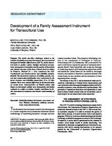
Design of a Sensorized Instrument for Skills Assessment and Training in Minimally Invasive Surgery Ana Luisa Trejos, Rajni V. Patel, Fellow, IEEE, Michael D. Naish, Member, IEEE, and Christopher M. Schlachta
Abstract—The restricted access conditions during minimally invasive surgery (MIS) result in perceptual-motor relationships that are unfamiliar to the novice surgeon and require training to overcome. To aid in MIS skills assessment and training, a novel sensorized instrument has been designed. Strain gauges attached to the instrument measure forces and torques acting at its tip, corresponding to all 5 degrees of freedom (DOFs) available during MIS. A position tracker provides tip motion feedback in 6 DOFs. The instrument is similar in shape, size and weight to traditional laparoscopic instruments, allowing it to be used in any MIS training environment. Furthermore, replaceable tips and handles make the instruments highly versatile. The results of the experimental evaluation show that there are clear differences in both the force and position profiles of trainees and surgeons with different levels of experience.
E
I. INTRODUCTION
surgery is a type of Minimally Invasive Surgery (MIS) in which long slender instruments and a camera enter the patient’s body through 1 cm incisions. Compared to open surgery, MIS significantly reduces tissue trauma, post-operative pain and recovery time. However, the fulcrum effect generated at the entry site reverses hand motion, requires higher manipulation forces to overcome the drag on the instruments, significantly reduces dexterity, and considerably degrades haptic feedback (the sense of touch). These limitations result in perceptual-motor relationships that are unfamiliar to the user and require training. The widespread application of MIS is hindered by the lack of appropriate educational and training tools. Current NDOSCOPIC
Manuscript received April 20, 2008. This research was supported by a grant from the Western Innovation Fund awarded to R.V. Patel; by the Natural Sciences and Engineering Research Council (NSERC) of Canada under grants RGPIN-1345 (R.V. Patel), and 312383-2005 (M.D. Naish); and by infrastructure grants from the Canada Foundation for Innovation awarded to the London Health Sciences Centre (Canadian Surgical Technologies & Advanced Robotics (CSTAR)) and to The University of Western Ontario (UWO) (R.V. Patel). A.L. Trejos is with CSTAR, Lawson Health Research Institute, 339 Windermere Road, London, ON, Canada and with the Department of Electrical and Computer Engineering, UWO, London, ON, Canada (phone: 519-685-8500 ext. 32529, email:
[email protected]). R.V. Patel is with CSTAR, the Department of Electrical and Computer Engineering and the Department of Surgery, UWO, (email:
[email protected]). M.D. Naish is with CSTAR, the Department of Mechanical and Materials Engineering, and the Department of Electrical and Computer Engineering, UWO, (email:
[email protected]). C.M. Schlachta is with CSTAR and the Department of Surgery, UWO, (email:
[email protected]).
training methods are inefficient—mastery of the required perceptual-motor skills takes longer than normal, posing a challenge to surgeons interested in acquiring these skills. It has been recognized that the education and training of clinicians in MIS is falling short of meeting health care needs [1]. To address this, research has been recently directed at developing methods for effectively assessing the level of expertise of surgeons and trainees. A step taken in this direction is the development of the McGill Inanimate System for Training and Evaluation of Laparoscopic Skills (MISTELS), which was developed as a standard for the evaluation of laparoscopic skills [2]. MISTELS is the skills component of the Fundamentals of Laparoscopic Surgery (FLS) program adopted by the Society of American Gastrointestinal and Endoscopic Surgeons (SAGES) and the American College of Surgeons. It consists of five tasks performed in a laparoscopic trainer box using inanimate materials. Studies suggest that skills learned in a laparoscopic box with the MISTELS program are transferable to the operating room environment [3]. However, a trained evaluator must be present to record measures and assess performance when using this system. These limitations have motivated the work presented below. II. BACKGROUND Several researchers have evaluated the assessment of surgical performance through the measurement of exerted forces or the motion profiles of the hands or surgical instruments. While not exhaustive, some of the relevant work in this area is summarized below. A. Force Sensing Force sensing systems for MIS have stringent design specifications that have limited their development. The specifications include [4,5]: the instruments must be less than 10 mm in diameter; they must sense forces from inside of the body due to high friction at the entry point; since different tools are used in each procedure, the instruments must be versatile; they must be fully sterilizable, and the sensor must be hollow to allow actuation of the tool jaws. Some researchers have approached the issue of force sensing during MIS by incorporating sensors into the gripper [6–9]. A few researchers have tried to sense forces directly on the shaft of the instrument [10]. However, most researchers have tried to sense the forces outside of the patient’s body, see e.g., [4,11–13]. The limitation of all of these systems is that the forces acting on the handle of the instrument are not an accurate representation of the forces
acting on the tissue (which are of primary importance when it comes to learning new procedures). Other researchers are looking at the effect of force sensing and haptic feedback in master-slave systems [5,14,15]. B. Position Sensing A solution to the problem of surgical instrument tracking in three-dimensional (3D) space would ideally use only the images acquired by the endoscope. Unfortunately, most of the current techniques deployed to track surgical instruments using digital image processing do not provide any depth perception from the endoscopic image. An exception is the work presented in [16], which places a colored marker on an instrument and relies only on the endoscopic image to track the instrument tip in 3D space. While promising, this approach is still limited in its ability to obtain real-time measurements and track more than one instrument at once. Commercially available tracking systems use specialized sensors to determine the position and orientation of an object in real time. Research involving the use of ultrasound, electromagnetic, fluoroscopic and optical trackers is often found in the literature; however, the most popular tracking systems are optical and electromagnetic. Optical tracking systems (OTS) are very accurate but require an unobstructed line-of-sight between the tracked object and the sensor. Electromagnetic (EM) tracking systems do not require an unobstructed line-of-sight and thus allow for unrestricted handling within their working volume. The sensors can be easily attached to various instruments and their poses tracked inside and outside of the patient. The main drawback of using electromagnetic trackers is that they can suffer from magnetic distortions in the presence of certain metals within their working volume. However, in well-controlled environments, such as surgical trainers, these effects can be minimized, obtaining tracking accuracies of 1 mm or less. C. Surgical Training Surgical tasks used for skill evaluation have been identified in [12] and include: peg transfers, pattern cutting, clip and divide, endo-looping, mesh placement, fixation, drilling, transferring small objects, making multiple defined incisions, suturing with intracorporeal or extracorporeal knots, and palpation. Measures include completion time, virtual position, virtual force and subjective checklists filled out by the user after the test. Some force or position feedback systems have been specifically developed for surgical training. In [17], position feedback is used to assess performance when performing MISTELS tasks in a training box with path measurement capabilities. Use of the application programming interface (API) for the da Vinci Surgical System (Intuitive Surgical, Inc.) is proposed in [18] for position feedback for surgical skills evaluation. A virtual reality laparoscopic trainer with haptic capabilities is proposed in [19]. In [20], the integration of force and position sensing was incorporated into the BlueDRAGON system for surgical training. The system uses two four-bar linkages equipped with position and force sensors that acquire the kinematics and dynamics of two endoscopic tools. The main limitations
of the system are that forces are measured outside of the trocar and that there is no consideration of the effect that the large manipulator would have on the normal movement of the laparoscopic instruments. Force/torque measurements have been used in [21] to objectively evaluate surgical skills in MIS. Finally, a virtual reality system to interactively train surgeons to perform minimally invasive procedures is presented in [22]. It simulates a surgical instrument with position and orientation feedback and some force feedback. The user interface is a one degree-of-freedom system consisting of a knob. The products currently on the market for surgical skills assessment and training are primarily surgical simulators. In these virtual reality simulators the main limitation is that the tips of the instruments are not acting on an actual object. The simulated haptic feedback is not a true representation of the forces that act on the instrument tips. Therefore, even if the software allows skills assessment, the lack of realism in the movement of the instruments compromises its applicability to real surgery. They also lack versatility, the video graphics have poor picture quality, and they are very costly systems. The exceptions are the LTS platforms by RealSim Systems. These complete surgical training platforms assess trainee performance and contain sensorized elements within the training box. However, their benefits do not translate to other environments like animal labs or real surgery. There is still a need for a system that can be used in any training scenario (laparoscopic trainer, animal labs or real surgery) for the purpose of skills assessment and training. D. Objective Based on the research developments outlined above and the limitations still present in current systems, the need for a sensorized, highly versatile and cost-effective laparoscopic instrument was identified. The specifications for the instrument were determined as follows: 1. The instrument must fit through a standard minimally invasive surgery port (10 mm max. outer shaft diameter). 2. It must be capable of measuring forces and torques acting in all 5 degrees of freedom (DOFs) available during MIS. These include the 3D forces acting at the tip, the torque about the instrument axis and the actuation force (grip, cut, etc.). 3. It must allow measurement of instrument tip position and orientation in 6 DOFs. 4. The overall appearance and weight must be similar to traditional hand-held laparoscopic instruments. This requirement is critical for the development of proper techniques when used in training. If the instrument is restricted at the entry point, or heavy cables are pulling down on the handle, the normal movement of the instrument will be compromised, and surgical skills might not be developed properly. 5. In order to increase versatility and reduce overall cost, it must allow attachment of interchangeable tips and handles depending on the task to be performed. 6. The software interface must allow the force and position data to be recorded in real-time.
III. PRESENTATION OF THE MECHANICAL DESIGN A sensorized laparoscopic instrument has been designed to meet the requirements outlined above. The instrument is composed of three concentric shafts. An inner shaft controls the opening and closing of the tip. A middle shaft provides rigidity to the instrument and connects the static components of the handle and the tip. An outer shaft “floats” over the middle shaft sealing the sensing elements from the environment, protecting them from moisture and wear. Fig. 1 shows the overall design of the instrument in two different configurations: a typical scissor-like handle with a gripper attachment and a needle driver handle and tip. The outer shaft is held by two o-rings. These o-rings seal the inside of the instrument from moisture and ensure that the outer shaft is firmly held in place. For ease of use, a rotating wheel allows the user to reorient the tip with respect to the handle to optimize ergonomic conditions. The instrument has been designed in a cost-effective and versatile manner with the addition of interchangeable tips and handles. The sensors are all attached to the middle and inner sections of the instrument. This way, the same sensorized elements can be used to perform the wide variety of tasks encountered during endoscopic surgical procedures by simply attaching different tips and handles. Strain gauges were employed to measure the deformation of the instrument shaft in order to determine the associated forces. The measurement of the forces can be divided into three main areas: the actuation force, the bending forces and the axial and torsional forces. In the analysis below, the coordinate frames have been assigned such that the z axis is in the direction of the instrument shaft, while the other two axes are perpendicular to the shaft. Actuation of the instrument tip is achieved by sliding the inner shaft of the instrument relative to the other shafts as the handle is opened and closed. The applied force when gripping or cutting is therefore directly related to the axial forces acting on this inner shaft. The cross sectional area of the shaft was locally reduced by machining a 1 mm thick flat section about 70 mm from the tip. This not only provided a better surface for gauge placement, but also significantly
increased the axial strain. Furthermore, in order to maximize the signal in the axial direction, four active strain gauge elements were used in a Type III Full Wheatstone Bridge configuration. Linear strain gauges were used to measure the bending moments caused by the forces acting at the tip of the instrument in the x and y directions. Two sets of two strain gauges were mounted on opposite sides of the shaft (see Fig. 2a) in a Half Bridge Type II configuration. Isolation of the axial force and torsion required the placement of two two-element rosette strain gauges on opposite sides of the shaft, Fig. 2b. Two 2.5 mm holes were drilled through the shaft in orthogonal directions to locally increase the strain caused by these forces. Each rosette contains two gauges placed at 90 degrees with respect to each other at a 45 degree angle from the centre axis of the gauge. The rosette elements were wired independently in a Type I Quarter Bridge configuration, also called a 3-wire connection. Connecting each of the four elements separately allows both the axial and the torsional forces to be isolated. The stresses that correspond to the different forces affect the four elements of the rosettes differently, and therefore allow the desired force or torque to be isolated by adding or subtracting the appropriate signals. Once the system is set up to measure strain on the instrument shaft, it is possible to determine the magnitude of the forces and torques acting in all 5 DOFs available during MIS. Simple mechanical calculations and knowledge of the material properties, shaft dimensions and the accurate location of the gauges are sufficient to compute the actual forces and torques that are being applied on the instrument tip. For the purpose of tracking instrument tip position, the microBIRDTM EM tracking system (Ascension Technology Corp.) was used. It consists of a custom (PCI) interface card, an EM transmitter, and two 6 DOF sensors with an outer diameter of 1.3 mm. A simple calibration process [23] allows the position of the instrument tip to be measured with respect to the position of the sensor.
Fig. 1. Instrument design with traditional handle and gripper attachment (top) and with needle driver handle and tip (bottom). Detail of the instrument design showing o-ring location for attachment of the outer shaft. The rotating wheel allows the user to rotate the distal end of the instrument in order to reorient the tip with respect to the handle.
(a) (b) Fig. 2. Placement of strain gauges on the outer shaft: (a) stain gauges measuring bending moment (gauges labeled A1 and B1 are wired together, while A2 and B2 form another half bridge), and (b) placement of the twoelement rosettes measuring torsion and axial forces.
IV. INSTRUMENT PROTOTYPE Two identical prototypes of the instruments were constructed from stainless steel (see Fig. 3). Each instrument weighed under 184 g. The scissor handles were constructed of ABS plastic. The needle driver handles used were obtained from commercially available laparoscopic needle drivers (R. Wolf, Inc.). The instrument tips include the Raptor Grasper tip, the Endocut Scissor tip and the SuperAtrau Raptor Grasper (Microline Pentax, Inc.). The needle driver tips were designed and constructed of stainless steel. The equipment used for capturing force and position information in real time is shown in Fig. 4. The system includes three major components: a personal computer (PC), the position sensing system, and the force sensing elements. As mentioned previously, the microBIRD™ tracking system was used for position sensing. This system connects directly to the PC through a PCI card. A customized software interface was developed in C++ to record the signals from the two EM sensors for offline analysis [23]. The tracking error was found to be less than 1.4 mm.
Laparoscopic training box
The strain gauges attached to each instrument are connected to seven Strain Gauge Amplifiers (Quanser, Inc.) which are powered by a Quanser Universal Power Module (model UPM-1503). The gain from these amplifiers ranges between 40 and 2000 depending on the potentiometer setting. Two Quanser Q8 Hardware-in-the-Loop boards (one for each instrument) are responsible for capturing the signal from the amplifiers. A Dell Computer was used with an Intel Pentium 4 Processor, 2.8 GHz, 1 GB RAM running Windows XP. This computer serves to capture and record data from the EM sensors. It also allows data from the strain gauges to be captured and processed using WinCon (Quanser Inc.) and Simulink (The MathWorks™). WinCon provides an integrated environment that allows a Simulink model to be run in real time. Using specialized control blocks for the Q8 boards, a Simulink model was created to record and display the signals from the strain gauge bridges. Calibration details for the system will be presented in [24].
Fig. 3. Instrument prototypes showing the attachment of different tips and handles.
PC for signal acquisition and display
Signal display
Sensorized instruments
Signal amplifiers
EMTS transmitter
Fig. 4. Experimental setup.
Power supply
Q8 interface boards
V. EXPERIMENTAL EVALUATION To evaluate the effectiveness of using the sensorized instruments, an experimental evaluation was conducted. A. Methods The objective of the experimental evaluation was to determine if the force and position profiles obtained when using the sensorized laparoscopic instruments for a simple task could be related to the user’s level of expertise. A total of 6 subjects performed an intracorporeal knot-tying operation 5 times. These subjects were all surgeons or surgical fellows, 2 at an expert level, 2 at an intermediate level and 2 at a novice level. They were instructed to complete a surgeon’s knot on a Penrose drain using the sensorized laparoscopic instruments inside a standard laparoscopic trainer box (model TRLCD03, 3-Dmed Surgical Training Aids), Fig. 5. This task is the same as the MISTELS knot-tying task. Fig. 6. Position trajectory for a novice surgeon (top) and an expert surgeon (bottom) when performing an intracorporeal knot in a minimally invasive training box.
Fig. 7. Forces exerted by a novice surgeon (top) and an expert surgeon (bottom) when performing an intracorporeal knot in a minimally invasive training box. The vertical scale represents the voltage measured by the strain gauge amplifiers, while the horizontal scale shows the number of data points measured. 0.045 0.04
p = 0.456
p = 0.845
Novice
Intermediate
p < 0.001
0.035 0.03 Voltage (V)
B. Results Fig. 6 shows typical position trajectories when the knot tying task is performed by a novice and an expert surgeon. The graphs clearly indicate a difference in the smoothness of the motion, in the range of motion and in the number of movements taken to complete the task, showing the effect of deliberate actions when an expert surgeon performs the task. Similar graphs are shown in Fig. 7 for the change in voltage in the strain gauge signals. The graphs for the expert surgeon show a characteristic peak at the end of the task corresponding to the tightening of the knot, while the forces remain low at all other times. The novice person shows high forces throughout the task and no peak at the end. These observations are confirmed by the analysis presented in Fig. 8. It was found that all subjects tightened the knot in the last 1/6 of the task; therefore, in this figure the average of the mean forces exerted in the x-y plane during the first 5/6 of the task is compared to those exerted during the last 1/6 of the task by the subjects at each experience level. The intermediate level subjects show a tendency to exert lower overall forces and a higher force at the end of the task, although the difference is not as pronounced as with the subjects at the expert level. The voltages shown in Figs. 7 and 8 correspond to the change in voltage caused by the stresses acting on the material below the strain gauges, which can be directly correlated to the forces applied at the tip. The magnitude of the actual forces is not shown, as only a relative comparison between the forces applied by the different users is of interest.
0.025 0.02 0.015 0.01 0.005 0
First
Fig. 5. Sensorized instruments performing a suturing task and a sample knot tied by an expert surgeon (inset).
Expert
Last
Fig. 8. Voltage corresponding to the force acting in the x-y plane during the first 5/6 of the knot tying task compared to the last 1/6 of the task.
VI. DISCUSSION AND CONCLUSIONS A sensorized laparoscopic instrument has been designed and two prototypes have been constructed. The novelty of these instruments can be summarized as follows: (1) The instruments measure all of the forces and torques acting in all 5 DOFs available during MIS. Electromagnetic sensors attached to the instruments provide position feedback in 6 DOFs. (2) Despite containing force and position sensors, the instrument is similar in shape, size and weight to traditional laparoscopic instruments. This not only allows surgical skills to be properly developed and assessed, but also allows the instruments to be used in any training environment, e.g., MISTELS, animal labs or real surgery. (3) The forces being measured are those acting on the tip of the instrument and not on the handle or at the port locations. (4) Replaceable tips and handles make the instruments more affordable since the shaft containing all of the sensing elements may be used for a variety of tasks. An experimental evaluation was performed to determine the effectiveness of using these instruments to assess trainee performance when performing a knot tying task in a minimally invasive manner. The results show that there are clear differences in both the force and position profiles of trainees and surgeons at different levels of experience. Ongoing work involves the development of software that is capable of objectively assessing trainee skill levels and providing real-time feedback on their performance. In order to accomplish this task, the instrument prototypes will be used to collect force and position data while subjects of all experience levels perform various MISTELS tasks. These tasks reflect typical surgical procedures, and can be methodically divided into steps with quantifiable parameters and well-defined intermediate goals. The database that results from these experiments will be used to determine the most effective ways of providing real-time feedback on trainee performance and assessment of surgical skill levels. Furthermore, software will be developed to allow vision-based position measurement of the instrument tip. This will not only significantly reduce the cost of the system, but will allow the instruments to be sterilized, provided that strain gauges and adhesives that can withstand the temperatures and humidity levels typical of a sterilization procedure are employed.
[4]
[5] [6]
[7] [8]
[9]
[10]
[11] [12]
[13] [14] [15]
[16] [17] [18] [19]
ACKNOWLEDGMENT
[20]
The authors would like to thank Kevin Barker, Jerry Dafoe, Shiva Jayaraman, Chris Ghazal, Martin Pytel, Mahdi Tavakoli, and the staff at CSTAR and Quanser Inc.
[21]
REFERENCES [1]
[2] [3]
R.J. Romanow (Commissioner), “Building on values: the future of health care in Canada—final report,” Commission of the Future of Health Care in Canada, 2002. Available online: http://www.hc-sc.gc. ca/english/pdf/romanow/pdfs/HCC_Final_Report.pdf A.M. Derossis, et al., “Development of a model for training and evaluation of laparoscopic skills,” Am J Surg, vol. 175, pp. 482–487, 1998. L.S. Feldman, S.E. Hagarty, G. Ghitulescu, D. Stanbridge, and G.M. Fried, “Relationship between objective assessment of technical skills
[22] [23]
[24]
and subjective in-training evaluations in surgical residents,” J Am Coll Surg, vol. 198, no. 1, pp. 105–110, 2004. S. Shimachi, Y. Fujiwara, and Y. Hakozaki, “New sensing method of force acting on instrument for laparoscopic robot surgery,” In Proc. Int. Conf. Computer Assisted Radiology and Surgery, International Congress Series, vol. 1268, Chicago, Illinois, 2004, pp. 775–780. M. Tavakoli, R.V. Patel, and M. Moallem, “Haptic interaction in robot-assisted endoscopic surgery: a sensorized end-effector,” Int J Med Robot Comp, vol. 1, no. 2, pp. 53–63, 2005. J. Dargahi, S. Payandeh, and M. Parameswaran, “A micromachined piezoelectric teeth-like laparoscopic tactile sensor: theory, fabrication and experiments,” In. Proc. IEEE Int. Conf. Robotics and Automation, Detroit, Michigan, 1999, pp. 299–304. K. Takashima, K Yoshinaka, T. Okazaki, and K. Ikeuchi, “An endoscopic tactile sensor for low invasive surgery,” Sensors and Actuators A, vol. 119, pp. 372–383, 2005. F. Van Meer, D. Esteve, A. Giraud, and A.M. Gué, “Si-micromachined 2D force sensor for a laparoscopic instrument,” In Proc. Int. Conf. Computer Assisted Radiology and Surgery, International Congress Series, vol. 1268, Chicago, Illinois, 2004, pp. 1334. G. Tholey, A. Pillarisetti, W. Green, and J.P. Desai, “Design, development, and testing of an automated laparoscopic grasper with 3D force measurement capability,” in S. Cotin and M. Metaxas (eds), Int. Symp. on Medical Simulation, LNCS 3078, 2004, pp. 38–48. P.J. Berkelman, L.L. Whitcomb, R.H. Taylor, and P. Jensen, “A miniature microsurgical instrument tip force sensor for enhanced force feedback during robot-assisted manipulation,” IEEE T Robotic Autom, vol. 19, no. 5, pp. 917–922, 2003. P. Dubois, “In vivo measurement of surgical gestures,” IEEE T BioMed Eng, vol. 49, no. 1, pp. 49–54, 2002. J. Rosen and B. Hannaford ”Markov modeling of minimally invasive surgery based on tool/tissue interaction and force/torque signatures for evaluating surgical skills,” IEEE T Bio-Med Eng, vol. 48, no. 5, pp. 579–591, 2001. G.B. Hanna, T. Drew, G. Arnold, M. Fakhry, and A. Cuschieri, “Development of force measurement system for clinical use in minimal access surgery,” Surg Endosc, vol. 22, pp. 467–471, 2008. B. Hannaford, et al., “Computerized endoscopic surgical grasper,” Proc. Medicine Meets Virtual Reality, San Diego, California, 1998, pp. 111–117. H. Mayer, I. Nagy, A. Knoll, E. Schirmbeck, and R. Bauernschmitt, “The EndoPAR system for minimally invasive robotic surgery,” In Proc. IEEE/RSJ Int. Conf. Intelligent Robots and Systems, Sendal, Japan, 2004, pp. 3637–3642. O. Tonet, R.U. Thoranaghatte, G. Megali, and P. Dario, “Tracking endoscopic instruments without a localizer: a shape-analysis-based approach,” Comput Aided Surg, vol. 12, no. 1, pp. 35–42, 2007. S. Cotin, et al., “Surgical training system for laparoscopic procedures,” Patent Application Publication No. US 2005/0142525 A1, 2005. H.C. Lin, I. Shafran, D. Yuh, and G.D. Hager, “Towards automatic skills evaluation: detection and segmentation of robot-assisted surgical motions,” Comput Aided Surg, vol. 11, no. 5, pp. 220–230, 2006. A. Maciel, et al., “Development of the VBLaST™: a virtual basic laparoscopic skill trainer,” Int J Med Robot Comp, early view publication, 2008. J. Rosen, et al., “The BlueDRAGON — a system for measuring the kinematics and the dynamics of minimally invasive surgical tools invivo,” Proc. IEEE Int. Conf. Robotics and Automation, Washington, DC, 2002, pp. 1876–1881. J. Rosen, et al., “Generalized approach to modeling minimally invasive surgery as a stochastic process using a discrete Markov model,” IEEE T Bio-Med Eng, vol. 53, no. 3, pp. 399–413, 2006. B.E. Bailey, “System for training persons to perform minimally invasive surgical procedures,” US Patent # 6,267,599 B1, Medical Simulation Corporation, 2001. M. Pytel, “The development of an image based navigation system for use in interstitial lung brachytherapy,” Master’s thesis, Dept. Elect. and Comp. Eng., The University of Western Ontario, London, Ontario, Canada, 2005. A.L. Trejos, R.V. Patel, M.D. Naish, and C. Schlachta, “A sensorized instrument for skills assessment and training in minimally invasive surgery,” ASME Journal of Medical Devices, under review, 2008.