1
Design of an automatic impedance matching system for industrial continuous microwave ovens. Part I: Modeling and o® line tuning V.C.Parro and F.M.Pait Abstract| The impedance matching is an essencial part of a microwave heating system in order to avoid re°ections and optmize the operations of generator. In some applications the load under heating has its impedance variable with time. In this case an automatic matching system is required. This paper presents a methodology to build an automatic matching system. The matching algorithm is based on gradient information and a o®-line tuning is proposed. Simulation results are presented and discussed. Keywords| impedance matching, gradient, microwave heating
I. Introduction
T
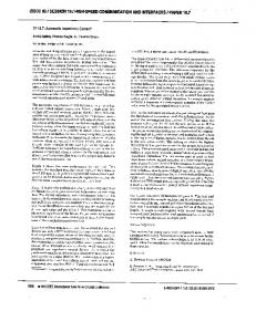
HE basic impedance matching problem can be illustrated in a simple form in ¯gure 1. The operation frequency (fop ) and de waveguide dimensions were determined for only the dominant mode TE10 propagates. The main objective is adjust the matching device in order to obtain a resultant impedance Zin , composed by the load impedance and the matching device, to be equal of the characteristic impedance of the waveguide (Zo ): If this objective is achieved there isn't re°ected signal and the system is matched. Other form of a matched system characterization is using the re°ection coe±cient de¯ned by equation 1 at the waveguide-matching device interface. The re°ection coe±cient, represented by ¡in ; is the ratio between the reR i and the transmited eletric ¯eld Ein °ected eletric ¯eld Ein : Re°ected Signal ER Zin ¡ Zo jµin = in : i = Z + Z = j¡in j e Transmited Signal Ein in o (1) The situation described, applied to a microwave heating, using an automatic system to adjust the matching device, was ¯rst analyzed by Wyslouzil et al [9],[10]. In his work Wyslouzil build an automatic system using the complete information about the re°ection coe±cient. The magnitude and phase of the re°ection coe±cient was estimated using small antennas positioned in a strategic way in the waveguide. This work was reproduced by Souza et al [1] and the results was compared and other solutions were discussed. An alternative to the measure system used by Wyslouzil is design an algorithm which can adjust the matching device using only the magnitude of the re°ection coe±cient. Two di®erent algorithms, based on a gradient information, ¡in =
V.C.Parro is with Escola de Engenharia Mau¶ a - Pra»ca Mau¶ a,01 S~ ao Caetano do Sul - SP CEP 09580-900 (e-mail:
[email protected]) F.M.Pait is with Escola Polit¶ ecnica da USP - Av. Luciano Gualberto, S~ ao Paulo - SP CEP xxxxx-yyy (e-mail:
[email protected]) This work was supported by Mau¶ a Institute of Technology.
ZG
Waveguide
Zo Reflected signal Generator
Matching Device
Load
ZL
Resultant Impedance
Zo
Fig. 1. Simpli¯ed microwave heating system diagram using a matching device.
were proposed and the results discussed in [2],[3],[4],[5]. A similar work was implemented by Chtcherbakov et al [6] applied to a plasma deposition presenting good results. The adjust algorithm based on arti¯cial intelligence algorithm was discussed in [7],[8]. The impedance matching system and adjust algorithm has been discussed in another important microwave area for microwave monolithic integrated circuits (MMIC) development. The results obtained was discussed in [11],[12]. II. Device Matching Description and Modeling The impedance matching system discussed in this paper is composed by four cylindrical tuning posts. These posts are separated themselves from a ¸g =8 distance and positioned in a rectangular waveguide according to the ¯gure 2. The waveguide dimensions 72mm from width and 36 mm from height. The post length is adjusted using a DC motor operating in open loop. .The length can be adjusted for 0 to 30 mm. The moving system is illustrated in ¯gure 3.The magnitude of re°ection coe±cient is determined by a data acquisicion system with 10 bits of resolution. The e®ects of data acquisition resolution and the mechanical resolution of the moving system are take into account in model. A simpli¯ed matching device model can be obtained negligecting the coupling e®ect between the posts. First, the characteristic of each post was obtained in an experimental essay. The scattering matrix (S) of each post was obtained using a network analyzer (HP8722) operating in 2.45GHz.
2
Post reactance 0
-0.5
ls
Reactance
-1
-1.5
-2
Fig. 2. Front view of the matching device. -2.5
-3 10
12
14
16
18 20 22 Length in mm
24
26
28
30
Fig. 4. Impedance matrix coe¯cients obtained for scattering matrix.
where ¢S(lj ) = S11 (lj )S22 (lj ) ¡ S12 (lj )S21 (lj ); and j¼ T(¸g =8) = cosh( ) 4 Fig. 3. Moving system detail.
Z = (I + S)(I ¡ S)¡1
(2)
Using the results described, one matching device model can be proposed according ¯gure 5. The posts are numbered from left to rigth, and the post 4 is near to the load. In order to obtain the global scattering matrix (SG (l1 ; l2 ; l3 ; l4 )) the transmission matrix (T) is used. For each post the transmission matrix (T(lj ))can be obtained for the scattering matrix (S(lj )) using equation 3. The global transmission matrix (TG ) is obtained applying 4.
T(lj ) =
¡¢S(lj ) S21 (lj ) S22 (lj ) S21 (lj )
S11 (lj ) S21 (lj ) 1 S21 (lj )
1 + tanh( j¼ 0 4 ) 0 1 + tanh( j¼ 4 )
¸
.
(4) TG (l1 ; l2 ; l3 ; l4 ) = T(l1 )T(¸g =8)T(l2 )::: :::T(¸g =8)T(l3 )T(¸g =8)T(l4 )
For waveguide application a TRL calibration method was used [15],[16],[14]. The post length was adjusted from 10 to 30mm with step of 2mm . For each position one scattering matrix was obtained. After this essay the results was compared and the behavior of the post is analogous a variable capacitor. This behavior is discussed in details by Harrington in [17],[18]. The result is better presented using impedance matrix (Z) instead of scattering matrix. The transformation can be obtained using 2. The ¯nal result for one post, using impedance matrix coe±cients, can be observed in ¯gure4.
"
·
#
(3)
1
2
Y1
λg/8
3
4
Y2
λg/8
5
6
λg/8
8
7
Y3
Y4
Fig. 5. Simpli¯ed model to the matching device.
III. Characterization of the Magnitude of Reflection Coefficient The re°ection coe±cient resultant for the matching device and the load association can be calculated using equation 5, where ¡l is the re°ection coe±cient of the load. This equation can be easily obtained by analyzing the °ux diagram for the ¯gure 6, where ai is the incident wave in i-acess and bj is the re°ected wave in the j-acess. In order to specify the algorithm the magnitude of the re°ection coe±cient was calculated for several loads. The results were plotted in a parametric form, ¯xing two post lengths and variating the others. This investigation reveal some interesting aspects. For example, considering a normalized impedance load zcn = 0:8 + j1:8 where the posts lengths
3
1 and 3 were adjusted with ls1 = ls3 = 15 mm and for posts 2 and 4 their lengths variating form 10 to 30mm, the magnitude of the re°ection coe±cient can be observed in ¯gure 7. In this case the minimum value of the magnitude of the re°ection coe±cient is between 0.6 and 0.7, which no satisfy the matching speci¯cation. Then, the adjustment must be applied to all pots. Modifying the posts lengths for the posts 1 and 3 to ls1 = 17:3 mm and ls3 = 20:1 mm other behavior is observed. Analyzing ¯gure 8, the minimum of magnitude of the re°ection coe±cient is between 0 and 0.1 which is acceptable for the matching problem. ¡in =
S11 (l1 ; l2 ; l3 ; l4 ) ¡ ¡l ¢SG (l1 ; l2 ; l3 ; l4 ) 1 ¡ S22 (l1 ; l2 ; l3 ; l4 )
a1
(5)
0.8 0.7 0.6 0.5 0.4 0.3 0.2 0.1 0 30
20
15
20 10 10 ls(2)
ls(4)
b2
S21V
30 25
Fig. 8. Magnitude of re°ection coe¯cient with ls1 = 17:3 mm and ls3 = 20:1 mm :
S11V
Load
S22V
re°ection coe±cient for posts 2 and 3, the results can be observed in ¯gure . The main aspect in this case is the characterization of an acceptable matching region. In this work if the magnitude of the re°ection coe±cient is inferior to 0.1 the system is considerate matched. Using this criteria, in ¯gure one of the matching region is around ls2 = 16 mm and ls3 = 21 mm: This reveals the resolution of the moving system must be better than 0:5mm in order to adjust the post length.
b1 S12V
a2
Matching Device Fig. 6. Flux diagram for the matching device connected to the load.
30 28 26 24
1
22
ls(3)
20
0.9
18
0.8
16 14
0.7
12
0.6 30
10 10
30
20 ls(2)
25
30
25
20 ls(4)
15
20 10 10
15 ls(2)
Fig. 9. Comportamento da fun»c~ ao gama em fun»c~ ao dos comprimentos ls2 e ls3 com ls1 = 17:3 mm e ls4 = 12:6 mm:
IV. The Algorithm and a off-line tuning method Fig. 7. Magnitude of the re°ection coe¯cient behavior with ls1 = ls3 = 15 mm:
Considering the posts 1 and 4 lengths with ls1 = 17:3 mm and ls4 = 12:6 mm, and plotting the magnitude of
Considering the model approximation and the partial information about the re°ection coe±cient an interactive algorithm was elaborated. This algorithm is based on an approximation of the gradient information. For a vector
4
LS = [ ls1 ls2 ls3 ls4 ]; the problem can be described in this way: min j¡in (LS ; ¡l (t))j
(6)
LS
J2 =
m=1
subject to 0 · lsj · 30 mm for j = 1; 2; 3; 4: The algorithm is resumed in a pseudo-code as follow described. Step 1. For k = 0 e i = 1, an arbitrary initial condition is chosen LS (0) where ls1 = ls2 = ls3 = ls4 = ls (0) ; Step 2. j¡(Ls (k); ¡c (k))j is measured. Step 3. For the post i; increase its length of ¢lsp and j¡(Ls (k + 1); ¡c (k + 1))j is measured. For a maximum magnitude of the re°ection coe±cient wich the system can be considered matched ¡admi : If j¡(Ls (k); ¡c (k))j < j¡admi j go to step 12; Step 4. If j¡(Ls (k + 1); ¡c (k + 1))j < j¡(Ls (k); ¡c (k))j and i < 5 , increment k, k = k + 1 and return to step 2, other way go to step 5; Step 5. Increment i; i = i + 1 and k = k + 1; Step 6. If i < 5 go to step 2, other way go to step 7; If Step 7. j¡(Ls (k); ¡c (k))j is measured. j¡(Ls (k); ¡c (k))j < j¡admi j go to step 12 other way go to step 8; Step 8. g(j¡(Ls (k); ¡c (k))j) is estimated, moving each post once at time by ¢lsp ;using: 2
6 6 g(j¡(Ls (k); ¡c (k))j) = 6 6 4
¢j¡en (Ls (k);¡c (k))j ¢lsp ¢j¡en (Ls (k);¡c (k))j ¢lsp ¢j¡en (Ls (k);¡c (k))j ¢lsp ¢j¡en (Ls (k);¡c (k))j ¢lsp
3
7 7 7: 7 5
Step 9. The search direction is determined using: g(j¡(Ls (k);¡c (k))j) ; d(k) = ¡ kg(j¡(L s (k);¡c (k))j)k 1
Step 10. For a constant gain gr ; the total adjustment is estimated using: ¢l(k) = gr : j¡(Ls (k); ¡c (k))j d(k); Step 11 . The posts are moved using the ¢l(k). Increment k, k = k + 1: j¡(Ls (k); ¡c (k))j is measured. If j¡(Ls (k); ¡c (k))j > j¡amdi j return to step 8. Other way go to 12; If Step 12. j¡(Ls (k); ¡c (k))j is measured. j¡(Ls (k); ¡c (k))j > j¡admi j ; return to step 8. Other way stay in 12. The parameters gr and ¢lsp were o®-line tuned for a set of 222 di®erent loads. The loads set is represented in the smith chart of ¯gure 10.The magnitude of the re°ection coe±cient for the load varying from 0.2 to 0.7 with 0.1 step and the phase of re°ection coe±cient varying from zero to 350 with 10 degree step. For each load the minimization algorithm was applied and an estimation of the total re°ected power was estimated using the function expressed by 7.
8 N P > > > > M < X k=0 > > > > :
(j¡m (Lsm (k);¡c (k))j2 +j¡m (Lsm (k¡1);¡c (k¡1))j2 ) 2
(kLsm (k) ¡ Lsm (k ¡ 1)k1 ) + ::: N P :::+ 8 j¡m (Lsm (k); ¡c (k))j2 ¢lsp : k=0
(7)
Conjunto de cargas 1 0.8 0.6
Parte imaginária do CR
0.4 0.2 0 -0.2 -0.4 -0.6 -0.8 -1 -1
-0.8
-0.6
-0.4
-0.2 0 0.2 Parte real do CR
0.4
0.6
0.8
1
Fig. 10. Set of loads representation in Smith chart.
Applying the algorithm for an impedance represented in a normalized form zn = 0:8 + j1:8, using ¢lsp = 0:120mm and gr = 96 the optimization trajectory can be observed in ¯gure 11.Varying the parameter ¢lsp an oscillation was observed and is illustrated in ¯gure 12. In ¯gure 13 it is possible to observe the behavior of the magnitude of the re°ection coe¯cient. The incorrect choose of ¢lsp became the slow in order to achieve the matched region. For smaller values for ¢lsp we observe a fast convergency. V. Conclusion The results shows that the proposed algorithm is adequate for the application and its application is feasible. A correct choose for the moving system resolution and a good tuning for the algorithm is the aim of the automatic impedance matching system. references [1] [2] [3] [4]
Souza, Jos¶ e Carlos & Luiz Paulo B. Fonseca & Marcelo de Moraes Zima - Casamento Autom¶ atico de Imped^ ancias em Microondas (TG0192) - Escola de Engenharia Mau¶ a, 1992. Souza, Jos¶ e Carlos - Casamento em guia de onda retangular utilizando como vari¶ avel medida a pot^ encia re°etida - Disserta»c~ ao de Mestrado - EPUSP, 1998. Parro, Vanderlei Cunha - Automa»c~ ao do Processo de Casamento de Imped^ ancia em Sistemas de Aquecimento Usando Microondas - Disserta»c~ ao de Mestrado - EPUSP, 1997. Souza, Jos¶ e Carlos et al. - An¶ alise do comportamento do m¶ odulo do coe¯ciente de re°ex~ ao na entrada de um conjunto casador toco triplo - Encontro Nacional de Software em Microondas e Opto-eletr^ onica - SBMO - Dezembro, 1997.
9 > > > > = > > > > ;
5
C om paraç ão do c om prtam ento do m ódulo do c oefic iente de reflex ão para diferentes valores de ∆ l sp
30
0.8 ∆ l ∆ l
28
∆ l
0.7
∆ l
sp sp sp sp
= 0.120 m m = 0.375 m m = 0.900 m m = 1.050 m m
26 0.6
Módulo do coeficiente de reflexão
24 22
ls(3)
20 18 16
0.5
0.4
0.3
0.2
14 0.1
12 10 10
15
20 ls(2)
25
0
30
Comportamento do Coeficiente de reflexao
0.2
∆ l = 0.120 mm sp
∆ l = 0.375 mm sp
∆ l = 0.900 mm
-1,1
sp
∆ l = 1.050 mm sp
Início
Parte imaginária de Gama
0
-0.1
-0.2
-0.3
-0.4
-0.2
0
0.2
0.4
0.6
0.8
Parte real de Gama -1,1
Fig. 12. Trajet¶ orias realizadas pelo coe¯ciente de re°ex~ ao para uma carga zn = 0:8 +j1.8, sintonizado com gr = 104; RSA=10 bits para quatrodiferentes valores de ¢lsp :
[5] [6]
[7] [8] [9]
20
40
60
80
100
120
140
Tem po -s
Fig. 11. Comportamento do comprimento dos ls2 e ls3 sintonizadores em rela»c~ ao as curvas de n¶ivel da fun»c~ ao gama para RSA = 12 bits, ¢lsp =0.120 mm e gr = 96 para para sintonia do algoritmo e zn = 0:8 + j1:8
0.1
0
Parro, Vanderlei Cunha et al. - Automa»c~ ao do processso de casamento de imped^ ancia em sistemas de aquecimento usando microondas - SBMO - Julho, 1998. Chtcherbakov A. A. & Swart P.L. - Automatic microwave tuner for plasma deposition applications using a gradient search method - Journal of microwave power and electromagnetic energy, 1997. Popov, Mikhail & Sailing He - Design of an automatic impedance-matching device - Microwave and Optical Technology Letters, 1999. Vai,Mankuan & Sheila Prasad - Automatic Impedance Matching with a Neural Network - IEEE Microwave and Guided Wave Letters, vol.3, no. 10, October, 1993. Wyslouzil, W. & A. L. VanKaughnett - An Automatic Tuner for Resonant Microwave Heating Systems - Journal of Microwave Power, 1971.
Fig. 13. Comportamento do m¶ odulo do coe¯ciente de re°ex~ ao para uma carga zn = 0:8 +j1.8, sintonizado com gr = 104; RSA=10 bits para quatrodiferentes valores de ¢lsp :
[10] Wyslouzil, W. & A. L. VanKaughnett -Automated Matching of Resonant Microwave Heating Systems - Journal of Microwave Power, 1973. [11] Lima R.N.de, Huyart B, Brgeault E. Nad Jallet L. - MMIC impedance Matching System - Electronic Letters - August, 2000. [12] Papapolymerou J., Lange K.L.,Goldsmith C.L.,Malczewski A. and Kleber J. - Recon¯gurable Double-stub tuners using MEMS switches for intelligent front-ends - IEEE Transactions on Microwave Theory and Techniques, volume 51, number 1,January, 2003 [13] Butler, John V., Sixteen-term error model and calibration procedure for on-wafer network analysis measurement, Master Thesis, University of Utah, 1991 Applying error correction to network analyzer measurements, [14] HP Application Note 1287-3, 1999. [15] Hoer, Cletus A., Engen,Glenn F., \Thru-Re°ected-Line": An improved technique for calibrating the dual six-port automatic network analyzer, IEEE Transactions on Microwave Theory and Techniques, vol. MTT-27, number 12, December, 1979. [16] Hoer, Cletus A. - A network analyzer incorporating two six-port re°ectometers - IEEE Transactions on Microwave Theory and Techniques, vol. MTT-25, number 12,December, 1977. [17] Harrington,R.F.,Lin, S.,Yang,N. Amiee, Y.Huang, Analysis of a post with arbitrary cross-section and height in a rectangular waveguide, IEE proceedings-H,vol.138, number 5, October, 1991. [18] Auda H. and Harrington R. F. - Inductive Posts and Diaphragms of Arbitrary Shape and number in a Rectangular Waveguide IEEE Transactions on Microwave Theory and Techniques, vol. MTT-32, number 6, June, 1984.