Downloaded from www.mroland.at
Parameter characterisation and automatic impedance matching of 13.56 MHz NFC antennas Harald Witschnig1, Michael Roland2, Martin Gossar3, Harald Enzinger4 1NXP
Semiconductors Austria Mikronweg 1, 8101 Gratkorn E-mail:
[email protected] 2School
of Informatics/Communications/Media, University of Applied Sciences Upper Austria Softwarepark 11, 4232 Hagenberg, Austria E-mail:
[email protected] 3Institute
of Electronics, Graz University of Technology Inffeldgasse 12, 8010 Graz E-mail:
[email protected]
4Department
of Industrial Electronicy, University of Applied Schiences Kapfenberg Werk-VI-Strasse 46, 8605 Kapfenberg E-mail:
[email protected]
Abstract: The underlying paper and investigations deal with the main functionality and physical parameters of contactless smartcard and NFC (Near Field Communication) devices. The specific need of impedance matching for reader devices is pointed out in particular, as the correct matching represents a major performance indicator of the system. Therefore, in a first step, the dedicated parameters are analyzed for a reader device. Based on these insights, detailed analysis of the concept, the implementation and the verification of an automatic impedance matching circuit for NFC antennas with a frequency of 13.56MHz is given. Besides an introduction to manual tuning and its issues, the fundamental components of an automatic tuning system are outlined. A lab-scaled prototype is built and demonstrated. Finally, the successful operation of this system is tested with several different antennas. Furthermore, the effects of detuning due to dynamic behavior are pointed out, characterizing the need for further investigations. Keywords: Automatic Tuning, Contactless Smartcard, Impedance Matching, NFC
Parameter Charaktierisierung und automatische Impedanzanpassung für 13,56 MHz NFC Antennen Kurzfassung: Das vorliegende Paper fasst die grundlegenden Funktionen und physikalischen Parameter für kontaktlose Smartcards und NFC (Near Field Communication) Einheiten zusammen. Die Notwendigkeit der Impedanzanpassung des Lesegeräts wird gezeigt, da die Anpassung ein wesentlicher Parameter für die Effizienz des Systems ist. Aus diesem Grund wird im ersten Schritt eine Analyse der grundlegenden Lesegerätsparameter durchgeführt. Basierend auf diesen Erkenntnissen und Ergebnissen wird ein detailliertes Konzept und eine mögliche Implementierung einer automatischen Impedanzanpassung für NFC Antennen bei einer Frequenz von 13,56 MHz vorgestellt. Neben dem manuellen Anpassen der Impedanz und den damit verbundenen Probleme werden die benötigten Komponenten für eine automatische Impedanzanpassung vorgestellt. Ein laborgerechter Prototyp wird aufgebaut und die erfolgreiche Arbeitsweise des Systems getestet und an verschiedenen Antennen gezeigt. Schlussendlich werden die Auswirkungen des Detunings basierend auf dynamischen Effekten dargestellt und die Notwendigkeit weiterer Entwicklungen gezeigt. Schlüsselwörter: automatische Impedanzanpassung, kontaktlose Smartcards, Impedanzanpassung, NFC
Received July 25, 2013, accepted September 9, 2013, published online November 7, 2013
This is a post-peer-review, pre-copyedit version of an article published in e & i Elektrotechnik und Informationstechnik (2009), 126/11. The final publication is available at Springer via https://dx.doi.org/10.1007/s00502-009-0693-6 e & i Elektrotechnik und Informationstechnik, 126 (11), pp. 415–422, 2009.
Downloaded from www.mroland.at
1.
Introduction
As a result of the evolution of different applications like access control, ticketing, payment and e-documents, the deployment of contactless smartcards and Near Field Communication (NFC) devices has been growing rapidly for several years. In particular mobile phones equipped with NFC technology open up a variety of potential new applications. Due to the variety of applications, it is obvious that a predefinition and implementation in terms of antenna geometry and corresponding parameters is hardly possible. Different applications show different needs in terms of achievable distance, antenna sizes … Therefore, a dedicated procedure for optimizing the reader and the card system is essential. Due to the fact that mobile phones tend to become smaller and smaller, especially the use of NFC in mobile phones raises some challenges related to the physical parameters and antenna parameters. They differ in shape and size, and there are usually tough space-saving requirements. Antennas have to fit casings of mobile devices. Consequently, using standardized NFC antenna designs is not the wanted solution with these devices. As a result, these non-standard antennas have varying characteristics, such as inductance and resistance. Current NFC transmission modules require the antenna circuitry to be manually matched with the integrated circuit (IC). This step is important to maximize the power of the emitted RF (radio frequency) field, and therefore, to maximize the range of the transmission module [1] and the quality of the transmitted signal, while keeping the power consumption of the transmitter low. Manual matching of the antenna characteristics is a rather lengthy and complicated procedure. Above this, only well matched reader devices fullfill the requirements according to the ISO 14443 standard, and thus, enable interoperability.
2. Basic Functionality of Contactless Smartcard and NFC Devices 2.1
General Description of Functionality
In general, contactless smartcards are pure passive devices. This means that the microcircuit has to power itself and provide power for the reply signal from the amount of energy that can be extracted from an interrogation (reader) signal. For inductively coupled 13.56 MHz systems, the necessary energy is provided by the magnetic field of the reader. This characteristic makes it obvious, that a well designed
Fig. 1. Main functionality of a passive HF RFID System [2] system (RF interface) is crucial for optimal performance. Fig. 1 depicts the basic principle of an inductive coupled RFID system: For inductive coupled systems the antennas are coils of a defined size. The link between these two coils is given by the magnetic field B. The value to describe this link is the mutual inductance M. Due to the generated magnetic field, as well as the mutual inductance between the two coils, energy and information is transferred from reader to card. Depending on the transmitted energy the card is activated and information is sent from card to reader through load modulation. This means, that by switching an impedance value on the card side, the magnetic field is loaded more or less, representing the symbols of the transmitted information. NFC shows some kind of exceptional position in this context, as an NFC device represents a reader as well as a card. Therefore, current NFC devices have two possible communication modes: passive mode and active mode. In passive communication mode, the initiator generates the RF field and the target answers to an initiator command in a load modulation scheme. In this mode, the target device may draw its operating power from the initiator-supplied magnetic field, what makes the target device a transponder as shown in Fig. 2(a). For the active communication mode, both, the initiator and the target use their own self-generated RF field to enable the communication (Fig. 2(b)). This is
e & i Elektrotechnik und Informationstechnik, 126 (11), pp. 415–422, 2009.
Downloaded from www.mroland.at
approximations exist. The approximation of the magnetic field strength for rectangular coils, as with NFC, is calculated as
1 1 0 i1 N a b 2 2 a x 2 b x 2 2 2 B 2 2 a b 4 x 2 2 2
(2)
In this equation, a and b are the lengths of the edges of a rectangular coil and x is the distance along the z-axis (orthogonal to the area of the coil). Mutual Inductance and Coupling Factor: Besides the magnetic field, the mutual inductance and the coupling factor between the two devices are particularly important. They are defined as
Bi1 dA2 and k i 1 A1
M Fig. 2. NFC has two communication modes also the standard mode for peer-to-peer communication.
2.2 Basic Equations and Physical Parameters The physical principle of inductively coupled RFID devices can be described by four main parameters. The following elementary equations and laws show these parameters. Magnetic Field: The most elementary physical parameter for HF RFID is the magnetic field strength, described by the law of Biot and Savart,
B
0 i1 ds x 4 S x 3
(1)
It allows the calculation of the magnetic field at every point in space as a function of the current i 1 and the geometry. In Eq. (1), μ0 describes the permeability, x is the distance and s describes the integration path around the coil. Although the law of Biot and Sarvart is well known and seems to be straight forward, an exact calculation is costly and only very few scenarios for reliable
M L1 L2
(3)
A2 describes the area of the second coil, while L1 and L2 describe the inductance of the two coils. It is obvious that the coupling factor has a significant influence on the functionality of the system. On the one hand, a higher coupling factor is necessary to ensure functionality, on the other hand, detuning effects will occur in case the coupling factor is too high, what in turn has a negative impact on the functionality. A predefinition of the expected coupling factor is difficult, as it strongly depends on the underlying antenna geometry. Fig. 3 shows two exemplary scenarios: Scenario one (NFC–NFC) describes the coupling factor between two NFC antennas (52 mm × 34 mm, six turns) of the same size, while scenario two (ISO–NFC) describes the coupling factor between an NFC device and an ISO antenna (75 mm radius and one turn, as defined in ISO 10373). It is obvious that the coupling factor, as well as the mutual inductance may vary significantly as a function of the geometry. Therefore, the geometry will have a significant impact on the overall functionality and performance. This makes countermeasures necessary. Quality Factor: The third parameter of major relevance in the characterization of passive HF RFID systems is the quality factor. The quality factor describes the losses of a coil, a crystal oscillator or a
e & i Elektrotechnik und Informationstechnik, 126 (11), pp. 415–422, 2009.
Downloaded from www.mroland.at
(a) Pulse simulation for Q = 20
Fig. 3. Coupling factor between two antennas as function of distance for NFC–NFC and NFC–ISO scenarios. The region with low coupling factors is highlighted resonant circuit. Different definitions of the quality factor exist, were in this investigation the following is used [1, 2]:
Q 2
Energy stored Energy dissipated per cycle
L RS f res B3dB
(4)
I1 L A QA
Fig. 4. Effects of the quality factor on the envelope of the seen voltage
(5)
(6)
The quality factor defines the super elevation of the resonant circuit in terms of current or voltage and, therefore, has a strong impact on the achievable energy transfer. The reader power, as a function of Q, is
P
(b) Pulse simulation for Q = 60
(7)
Eq. (7) states that, for the same generated magnetic field, more power is necessary with a low quality factor. At the same time, a high quality factor limits the bandwidth of the system, resulting in a lower possible transmission rate. Fig. 4 shows this effect on the envelope of the seen voltage.
Fig. 5 Equivalent circuit of an RFID transponder Therefore, the quality factor is a trade-off between maximum transferred power and maximum transmitted information. In particular the trade-off between high and low quality factors makes the need of a proper design and correct matching obvious. Operating Voltage at the Transponder: Besides the previously mentioned characteristics, the voltage seen at the IC is of significant relevance, as this value allows the functioning of a device.
e & i Elektrotechnik und Informationstechnik, 126 (11), pp. 415–422, 2009.
Downloaded from www.mroland.at
The voltage is derived from the equivalent circuit (Fig. 5), which consists of the following elements: induced voltage Uind, inductance L2 of the transponder, parasitic resistance R2, capacity CL of the IC (necessary for adequate tuning), and, finally, the load resistance RL, representing the impedance of the IC. The voltage at the IC is
U2
jMi1 jL2 R2 1 jC L 1 RL
(8)
Due to the fact that
1 jC L RL
(9)
devices range from simple SWR (standing wave ratio) meters to fully automatic ATUs (antenna tuning units). An SWR meter allows even an inexperienced user to optimize an antenna whereas ATUs usually do not require any user interaction at all. These approaches have also been successfully implemented into long-range RFID technology. Unfortunately, ATUs typically use relays and other large discrete components. Consequently, they do not fit into mobile handsets/readers. As a result of the complicated nature of manual impedance matching, automatic tuning significantly simplifies the development of RF applications. Therefore, once integrated into NFC transmission modules, automatic tuning will boost the usability of such integrated circuits. This paper provides an insight
Eq. (8) can be simplified to
U2
jMi1 jCL R2 1 2 L2CL 1
(10)
L 1 and Q2 r 2 L2C2 R2
(11)
Substituting
r2 leads to
U2
jMi1 1 2 j 1 r Q2 r2
(12)
Eq. (12) suggests, that the operating frequency (relative to the resonance frequency, / r ), as well as the quality factor Q2 have a significant influence on the voltage seen at the IC. Consequently, a correct matching (in terms of impedance, resonance frequency and quality factor) has a major influence on the overall performance of the system. Based on these considerations, it is obvious that correct matching of the reader, as well as the transponder device is crucial for the overall system performance. The following section explains such a matching procedure for an NFC device – from a theoretical point of view, as well as from a first practical approach.
3. Manual Impedance Matching for NFC Devices There is a history of automating the matching procedure for technologies where space-saving is not a main effort. With citizen’s band radio and ham radio,
(a) Transmitter supply current vs. load resistance
(b) Emitted RF power vs. load resistance Fig. 6. Power consumption and power emission vs. load resistance for NXP’s PN511 NFC transmission module at the operating frequency of 13.56 MHz [3]
e & i Elektrotechnik und Informationstechnik, 126 (11), pp. 415–422, 2009.
Downloaded from www.mroland.at
into automating the tuning procedure for 13.56 MHz NFC antennas, while using maximum possible integrable components. NFC transmission module ICs use external antennas to communicate with other NFC/RFID enabled devices. The antennas vary in shape and size, whereby each antenna has different impedance measured at its clamps. The impedance of the antenna is the load resistance of the NFC IC’s transmitter circuit. Fig. 6 shows the relation between transmitter supply current and emitted RF power over the load resistance at the transmitter’s clamps (at 13.56 MHz). The maximum power of the emitted RF field is yielded at 30 ohms, while the transmitter supply current decreases with increasing load resistance. Thus, the optimum in terms of supply current is reached with a high (above 60 ohms) load resistance and the optimum in terms of emitted RF power is at 30 ohms. Fig. 6 suggests that a good tradeoff between transmitter supply current and emitted RF power is at 40 to 50 ohms [3]. Therefore, the impedance of the antenna should be matched to 50 ± j0 ohms.
Fig. 7 Symmetric NFC antenna topology with EMC filter, matching circuit, quality factor damping resistors and antenna coil [3]
To achieve the matching, the antenna circuitry (Fig. 7) consists of three parts:
an electromagnetic compatibility (EMC) filter (L0, C0),
a matching circuit of series and parallel capacitors (C1, C2) to perform the actual tuning,
and the antenna with quality factor damping resistors (RQ).
The EMC filter reduces harmonics of the 13.56 MHz carrier and performs an impedance transformation. It must have a fixed resonance frequency which is the sum of the operating frequency and the subcarrier. The subcarrier is 847 kHz [1], [4]. This results in a resonance frequency of 14.407 MHz.
(a) Flow chart for tuning process
The coil of the antenna produces the magnetic (RF) field. The antenna has additional quality factor damping resistors (RQ). These resistors are primarily necessary to adjust the quality factor of the antenna to obtain a certain pulse shape as required by the standard [4]. Manual tuning is accomplished by measuring the reflection coefficient (S11 parameter) of the antenna circuitry (Fig. 7, clamps TX1 and TX2) at the operating frequency of 13.56 MHz. The impedance of the antenna circuitry follows the equation [5]
(b) Sweep measurement of the reflection coefficient S11 of a matched antenna between 10 and 20 MHz with a marker at 13.56 MHz Fig. 8. Tuning process and its results
e & i Elektrotechnik und Informationstechnik, 126 (11), pp. 415–422, 2009.
Downloaded from www.mroland.at
Fig. 10. Measurement system based on a Wheatstone bridge with a sinusoidal supply of 13.56 MHz
Fig. 9. Automatic tuning system design split into its three components: measuring circuit, matching circuit and controller component [6]
Z S11 Z L
1 S11 with Z L 50 1 S11
(13)
Consequently, an impedance of 50 ohms is obtained when S11 is zero at 13.56 MHz. Matching is achieved by alternately adjusting the capacitors C1 and C2. Fig. 8(a) shows the flow chart of the tuning process and Fig. 8(b) plots the reflection coefficient S11 of a matched antenna for frequencies ranging from 10 to 20 MHz with a marker at 13.56 MHz.
4.
Automatic Impedance Matching
Manual tuning of the matching circuit takes long and requires a good sense of choosing the right capacitor values. Moreover, expensive equipment such as an impedance analyzer or a network analyzer is needed. Therefore, automatic tuning significantly simplifies the development of RF applications. There are several existing methods of automatic impedance matching for other RF technologies. For example, automatic tuning devices for long-range RFID readers use large non-integrable components such as relays to achieve the tuning. Many NFC devices are integrated in mobile handsets, thus, it is not possible to realize this type of automatic tuning circuit for NFC. The ideal automatic tuning circuit consists of only integrable parts. The following sections present the concept and the implementation of the automatic impedance matching circuit. The complete automatic tuning setup, as shown in Fig. 9, consists of a measuring circuit, a matching circuit and a controller.
4.1
Measuring Circuit
The measurement for manual tuning is done with an impedance analyzer or a network analyzer. A network analyzer uses a directional coupler to determine the reflection coefficient of the antenna circuitry. As discussed in [7], using a directional coupler has several major disadvantages, such as power dissipation and difficulties with embedding into an IC. Therefore alternative concepts are investigated coming to the proposal consisting of the following elements. Measuring Bridge: Ref. [7] proposes an alternative to the determination of the reflection coefficient. The impedance of the antenna circuitry (at the frequency of 13.56 MHz) is measured instead. More precisely, the impedance is compared to a 50 ohms resistor. Fig. 10 shows the matching of the antenna impedance using a Wheatstone bridge. As source for the bridge a waveform generator providing a 13.56 MHz sinusoidal signal is used. The resistors R1, R2 and R3 each have a fixed value of 50 ohms. Based on Kirchhoff’s circuit laws, the Wheatstone bridge is described by the equations
I1 I 2 I diff 0
(14)
I 3 I Z I diff 0
(15)
I1 R1 I 3 R3 Vdiff
(16)
I1 R1 I 2 R2 I 3 R3 I Z Z
(17)
and
The antenna circuitry’s impedance Z matches 50 ohms,
e & i Elektrotechnik und Informationstechnik, 126 (11), pp. 415–422, 2009.
Downloaded from www.mroland.at
Fig. 12. Network of parallel capacitors Fig. 11. Non-inverting and inverting rectangle shaper and the phase detector of a 74HC4046A integrated circuit used for phase offset measurement
Z R2
R3 50 R1
(18)
when the bridge is balanced (Vdiff = 0). Therefore, the antenna is tuned when both – the magnitude and the phase of Vdiff – are zero. The voltages I 2 R2 and
I Z Z are used instead of directly measuring Vdiff.
Amplitude Measurement: Measuring rectifiers are used to rectify the magnitudes of I 2 R2 and I Z Z . Each rectifier cuts off the negative half-wave of its input signal [8]. The resulting signals are low pass filtered and amplified to fit the input range of an analog-digital converter. The difference between the two signals is calculated after analog-digital conversion. Phase
VSINE1
Measurement: The sinusoidal signals I 2 R2 and VSINE2 I Z Z are shaped into
rectangular signals. At the same time one of the signals is inverted (or shifted 180 degrees). These steps are necessary to transform the input signals into the operating range of the phase detector. Then, the phase of Vdiff is determined with the phase detector of a 74HC4046A phase-locked loop integrated circuit (Fig. 11). This IC outputs the phase offset as a pulsewidth modulated (PWM) signal. That PWM signal is low pass filtered and then fed into an analog-digital converter. The average voltage of the pulse-width modulated signal has a linear relation to phase offsets between −135 and +135 degrees. Verification: The measuring circuit is verified with a manually tunable antenna circuitry. The manual tuning circuit is based on Fig. 7. The fixed size capacitors C1 and C2 are replaced with trimmer capacitors. This antenna circuitry is connected to the measuring bridge. The trimmer capacitors are tuned until both the amplitude measurand and the phase measurand
approximate zero. In the next step the antenna circuitry is measured with a network analyzer instead of the measuring circuit. The S11 parameter for 13.56 MHz is close to zero. This verification procedure has successfully been repeated with several different NFC antennas. The deviation of the S11 parameter (at 13.56 MHz) is approximately identical to all antennas. This suggests that the deviation is a result of component variations in the measuring circuit.
4.2
Matching Circuit
Matching is done by varying the capacitance of C1 and C2 (Fig. 7). Ref. [7] suggests three types of variable capacitors:
trimmer capacitors,
capacitance diodes and
capacitance arrays.
Mechanic trimmer capacitors are neither integrable nor electronically controllable [7]. With capacitance diodes there is insufficient isolation between the signal voltage and the control voltage [7]. Thus, the best of these options is to use capacitance arrays. A capacitance array is a network of parallel switched capacitors (Fig. 12). The capacitors are graded with powers of two to achieve a binary coded capacitance value. The capacitance array is made electronically controllable with semiconductor switches. As the capacitor values range from 1 to 50 pF, low-capacitance DMOS switches are used. The capacitors C 1 and C2 are replaced with these capacitance arrays. The arrays are switched in a way that both instances of C 1 (and both instances of C2 respectively) have the same value. The DMOS switches have parasitic effects which make them operate differently to ideal switches. There is parasitic capacitance between the switched pins during off-state and between the signal pins and ground. These parasitics narrow the range of the capacitance arrays and therefore, narrow the range of
e & i Elektrotechnik und Informationstechnik, 126 (11), pp. 415–422, 2009.
Downloaded from www.mroland.at
tunable antennas. Moreover, there is an on-state resistance that influences the antenna’s quality factor. Thus, additional investigation of this problem is subject to prospective research.
4.3
Controller
A microcontroller is used to analyze the measurands and to control the capacitance arrays. The microcontroller has an integrated analog-digital converter to digitize the amplitude values and phase values. As proof of concept, a primitive tuning algorithm has been developed. The optimal adjustment of C1 and C2 is where the magnitude and the phase offset are the closest possible to zero. Both C1 and C2 have an impact on the magnitude as well as the phase offset. When each pair of measurands is considered as point on a two-dimensional plane, its distance d to zero can be calculated by the formula
d 2 A2 2
(19)
with the magnitude A (as the first coordinate) and the phase offset (as the second coordinate). Hence, the tuning algorithm has to find the minimum distance. The actual algorithm sweeps through all combinations of C1 and C2 and searches the lowest value of d2. The antenna circuitry is tuned to this combination of C1 and C2. The complete automatic tuning system has been tested with four different NFC antennas. The four antennas have symmetric rectangular coils with average dimensions of about 50 mm by 30 mm and four to six turns. Table 1 lists the tested antennas with the number of turns and the values of their series equivalent circuits [3, 7]. Moreover, it specifies the necessary values for manually tuning C1 and C2 (with L0 and C0 of the EMC filter at 560 nH and 220 pF) as obtained through simulation. The results were examined with a network analyzer. The algorithm found
Antenna 1 Antenna 2 Antenna 3 Antenna 4 6
6
(b) Antenna 2
(c) Antenna 3
(d) Antenna 4
Fig. 13. Sweep measurement of the reflection coefficient S11 of the automatically matched antennas between 10 and 20 MHz with a marker at 13.56 MHz the optimum values for C1 and C2 with each of the four antennas. Fig. 13 shows the smith charts for these antennas. With three of the four antennas, the marker (13.56 MHz) is almost exactly at zero. While antenna 4 is still tuned to an acceptable result, this is an example for the low resolution of the capacitance arrays. Antenna 4 (with a binary switching value of three for C1) and antenna 2 (with a binary switching value of zero for C2) mark the lower limit of the capacitance arrays: C1 can be tuned if a capacitance of more than 13 pF is required and C2 can be tuned if a capacitance of more than 49 pF is required. Based on these results it is concluded that a proof of concept is given. Further improvements and enhancements to a broader field of antennas is topic of further research.
5
Table 1. List of tested antennas
Turns
(a) Antenna 1
4
6
Ra
4.93 Ω
8.82 Ω
4.83 Ω
5.16 Ω
La
3.12 μH
3.16 μH
1.7 μH
3.49 μH
Ca
9.84 pF
10.16 pF
6.99 pF
6.35 pF
C1
14 pF
19 pF
27 pF
13 pF
C2
55 pF
49 pF
124 pF
54 pF
On the Effect of Detuning
The above concepts and strategies have the primary aim to implement a reliable matching based on a single and static NFC device. Besides this static matching, it is the dynamic behavior of the system which is essential to be characterized. Simply by approaching two devices, a significant impact on the mutual inductance and coupling factor can be seen. This effect is very strong in the case of two devices of the same size, as it is the case for an NFC card and an NFC reader device.
e & i Elektrotechnik und Informationstechnik, 126 (11), pp. 415–422, 2009.
Downloaded from www.mroland.at
6.
(a) S parameter of a reader antenna
(b) Antenna voltage at the reader and the transponder
Summary and Outlook
This paper presents an overview of the main parameters of HF-RFID/contactless smartcard devices in the context of functionality and characterisation. Based on that, a detailed view and analysis on NFC is given. After explaining the coupling factor and the influence of the quality factor on the signal, a method for integrating automatic impedance matching capabilities into NFC transmission module ICs is presented. The concept of an automatic tuning system is explained. The various aspects of the system, with a major focus on the measurement, are pointed out. Proof of concept is given by the implementation and the verification of a labscaled prototype. The proper operation of the automatic impedance matching system could be confirmed. The optimization of the capacitance arrays, the improvement of the tuning algorithm, the integration of the whole system into a single IC, as well as the enlargement of the array to be able to tune more antennas are subject to future research.
References
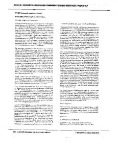
Fig. 14. Detuning effects on a coupled NFC device
1.
Finkenzeller, K. (2006): RFID-Handbuch, 4th ed. Carl Hanser Verlag München.
This has a significant influence on the tuning, as well as the physical parameters like voltage and current. Fig. 14 shows the effect of detuning. The 50 Ohm matching is changed significantly, when bringing the second NFC device from a distance of 50 mm to a distance of 5 mm. Equivalent to the detuning, the voltage at the reader and transponder also changes depending on the coupling factor. It can be observed that the voltage at the transponder increases rapidly when the coupling factor increases, but at a certain point, the voltage decreases when further increasing the coupling factor (due to the effect of detuning). Caused by the simplified simulation model it is possible that the voltage reaches up to 40 volt, which would be avoided by a limiter circuit to protect the IC. At the same time the reader voltage decreases with increasing coupling factor due to the effect of detuning. Different matching and antenna topologies have been investigated to compensate this effect, being a matter of patent proposals. Nevertheless, the example points out impressively that a dynamic antenna matching becomes relevant as soon as the coupling factor reaches a certain value.
2.
Witschnig, H. and Merlin, E. (2006): “Über Geschichte, physikalische Grundlagen und Applikationen der RFID Technologie,” e & i (Elektrotechnik und Informationstechnik), vol. 123, no. 3.
3.
Philips Semiconductors (2004): PN511 Transmission Module – Antenna and RF Design Guide.
4.
Ecma (2004): Near Field Communication Interface and Protocol (NFCIP-1), Ecma International Std. ECMA-340, Rev. 2.
5.
Klein, W. (1976): Mehrtortheorie, 3rd ed. AkademieVerlag Berlin, 1976.
6.
Roland, M., Witschnig, H., Merlin, E., and Saminger, C. (2008): “Automatic Impedance Matching for 13.56 MHz NFC Antennas,” in Proceedings of the 6th International Symposium on Communication Systems, Networks and Digital Signal Processing. Graz, Austria: IEEE, pp. 288–291.
7.
Malle, O. (2007): “RFID-Antennentopologien und deren automatische Leistungsanpassung,” Diploma thesis, Institut für Breitbandkommunikation, Technische Universität Graz.
8.
Tietze, U. and Schenk, C. (1999): Halbleiter-Schaltungstechnik, 11th ed. Springer Verlag Berlin Heidelberg New York, 1999.
e & i Elektrotechnik und Informationstechnik, 126 (11), pp. 415–422, 2009.
Downloaded from www.mroland.at
Authors Harald Witschnig was born in Friesach, Austria in 1975. He received the Dipl.-Ing. degree and the Dr. techn. (Ph.D.) from the Johannes Kepler University of Linz, Austria, in 1999 and 2004 with honours. From 2000 to 2004 he was assistant professor at the Institute for Communications and Information Engineering at the University of Linz, Austria. Since 2004 he is with Philips/NXP Semiconductors, Research and Development Center for RFID and contactless Smart-Card technologies. He has been engaged in research and development of broadband wireless communication systems, in particular on the topic of single carrier transmission with frequency domain equalization and multicarrier transmission. His current research activities are focused on RFID, contactless SmartCard systems and Near Field Communication. Within these fields he published 50 papers in refereed journals and conference proceedings and contributed several standardisation proposals at ISO. Michael Roland was born in Linz, Austria, in 1984. He is a student of Embedded Systems Design at the Upper Austria University of Applied Sciences in Hagenberg, Austria. In 2007 he made an internship at NXP Semiconductors Gratkorn, Austria. He received his B.Sc. degree in Hardware/Software Systems Engineering in 2007 with honours. At the moment he is working on his master’s thesis about Very High Data Rates for RFID/NFC systems at the NFC Research Lab Hagenberg in cooperation with NXP Semiconductors Gratkorn.
Martin Gossar was born in Graz, Austria, in 1984. He finished the diploma studies on electrical engineering at the Graz University of Technology (Dipl.-Ing.) in 2008. At the moment he is working on his PhD about Very High Data Rates for RFID systems at the Institute of Electronics at the Graz University of Technology in cooperation with NXP Semiconductors Gratkorn. Harald Enzinger was born in Judenburg, Austria, in 1986. He is a student of electronic engineering at the University of Applied Sciences Kapfenberg, Austria. In 2008 he made an internship at NXP Semiconductors Gratkorn, Austria, and now he is working on his diploma thesis concerning Very High Data Rates for contactless Smart-Card systems at the same company.
e & i Elektrotechnik und Informationstechnik, 126 (11), pp. 415–422, 2009.