The TP-UART-IC provides a convenient basis for a versatile KNX PC interface. ...
While the TP-UART handles most of the KNX protocol stack .... easy manual
soldering. ...... exceed 80 × 100 mm, changes can be made using EAGLE Light
Edition, which ... 5th IFAC Intl. Conference on Fieldbus Systems and their
Applications.
Design of an enhanced TP-UART based KNX PC interface Georg Neugschwandtner
Andreas Fernbach
Automation Systems Group Institute of Automation Vienna University of Technology Treitlstraße 1-3, A-1040 Vienna, Austria {gn, afernbach} @ auto.tuwien.ac.at
The TP-UART-IC provides a convenient basis for a versatile KNX PC interface. However, its host protocol contains timing constraints that are difficult to meet on a PC. This paper presents the design of such an interface that addresses these issues without sacrificing flexibility. It also documents properties of the TP-UART host protocol that were uncovered during development and are not described in its data sheet.
1 Introduction Although designed for interfacing microcontrollers that operate KNX devices to the TP1 medium, the Siemens TP-UART-IC [1] – in the following simply referred to as “TP-UART” – can also be used to build a simple yet highly versatile TP1 network interface for PCs. For example, such an interface has benefits in a lab environment since the TP-UART host protocol places very few restrictions on the frame format. While the TP-UART handles most of the KNX protocol stack up to the data link layer (and thus, the most critical timing requirements), higher level protocol aspects remain with the host controller. This leaves ample leeway for, e.g., testing protocol extensions. A TP-UART based PC/KNX interface may also have benefits in the early prototyping stage of (TP-UART based) embedded KNX devices. In addition, it can be a simple solution for traffic intensive applications (e.g., visualization software) that require an interface with wirespeed performance. Therefore, it is not surprising that various TP-UART based PC/KNX interfaces have seen the light of day. Besides the TP-UART IC itself, such an interface must at least include the support circuitry required by the TP-UART and convert between standard logic levels and those used by EIA/TIA232 (in the following referred to as RS-232 for brevity). A design that also provides galvanic
1
separation between the KNX network and the PC was used and published in 2001 by the FH Deggendorf [3] and was converted from surface-mount to pin-through-hole components at the Automation Systems Group, TU Vienna in 2003 [3]. Disch Systems offers a product that adds an enclosure as well as access to the temperature warning and protocol speed signals of the TP-UART [5]. The Siemens “Bus Transceiver Module” [6] can also be used if combined with a KNX serial interface application module. It then provides access to the TP-UART reset and link power failure warning signals. However, the TP-UART host protocol – being designed for microcontroller interfacing – still contains some relatively tight timing constraints. While these are not a serious problem for a microcontroller to handle and can be considered a fair price to pay for the flexibility of the protocol, a PC without a real-time operating system will hardly be able to meet them. Linux kernel drivers have been developed to address this problem [8, 9, 11]. However, a kernel driver is operating system dependent and requires significant maintenance effort (cf. [10]). Moreover, it introduces an additional proprietary protocol layer, which can be an obstacle if program code is to be transferred to an environemnt where such a driver is not necessary. Operating system independent user mode solutions are possible [12], but require assumptions about the frame format and special attention to recovery from error conditions. The goal of the project described in this paper was to obtain a solution that would allow to use the full flexibility of the TP-UART host protocol through a generic, operating system and programming language neutral serial port abstraction. Any modifications to the protocol were to be stateless and as small as possible. This was achieved by placing an MCU (microcontroller unit) between TP-UART and PC which monitors the timing of the critical TP-UART services and converts it to out-of-band communication where applicable. An appropriate hardware platform was designed that allows putting this approach into practice conveniently, but is versatile enough not to be limited to this single task. In the following, the interface hardware and how it can be used to address the TP-UART host protocol issues are described. Dealing with these issues requires detailed information about the protocol. Thus, tests were made to complement the information given in the data sheet [1]. Results obtained in the course of these efforts are described as well.
2 Hardware The design of the interface hardware follows the overall goals of being simple to build and easy to handle. Also, no particularly expensive software or hardware tools should be required. Still, the interface should provide a certain amount of versatility. In-system programming and debugging is standard on current MCU types and was to be included. However, there was also to be a minimal user interface to control the MCU behaviour as well as to trigger actions (such as sending a test network message) and show status information (e.g., error conditions) without reprogramming, requiring a debug interface connection or using the RS-232 interface for this purpose. Also, access to the TP-UART status signals should be possible. The KNX TP1 medium is electrically isolated to ground. On the other hand, the RS-232 interface on the PC is grounded. Therefore, galvanic isolation between the KNX and the PC side of the interface should be provided. Although the interface is primarily intended for laboratory
2
use, this was made a requirement to avoid problems in case the interface should be connected to a larger KNX installation.
2.1 Selecting the MCU The MCU is a key design component. Within this project, its task is not resource intensive with regard to processing power, memory size or I/O. It mainly consists of communicating via two relatively low speed UARTs (Universal Asynchronous Receiver Transmitter) and checking the timing of incoming messages. Thus, it can be optimized for low power consumption and easy manual soldering. In line with the overall project goals, the price of the programming adapter and toolchain necessary for developing and debugging the MCU software also have considerable impact. First, MCU types available in packages with low pin count and large pin spacing (at least 1 mm) were selected from popular product families. Evaluating the types on this shortlist according to the above criteria, the TI (Texas Instruments) MSP430-F123 [14] (and its F1232 sibling [15], which can be considered identical for the purposes of this project) emerged as ideally suited for the project. It provides a 16 bit RISC CPU, 8 kB Flash memory, 256 Bytes RAM, and can operate at clock rates of up to 8 MHz. Even at 8 MHz, it consumes less than 3 mA in active mode. In-system programming and debugging are possible via a standard JTAG (Joint Test Action Group) interface. Low-cost JTAG adapters are available. Entry level versions of two commercial toolchains are offered free of charge. In addition, a GCC based open source toolchain exists. The MSP430-F123 is available in a 28-pin small-outline package with 1.27 mm pin spacing (the same as the TP-UART-IC has). The MSP430-F123 has only one hardware UART (no MCUs in this class appear to be available that would have two; rather, many have none at all). This means that the UART function has to be implemented in software, using a hardware timer. While the MSP430-F123 has only one 16 bit hardware timer, it is equipped with three capture/compare units. Using one of these units for software UART transmission and one for reception, full duplex operation with minimum CPU load is possible. The third capture/compare unit remains free for application timing tasks. TI even provides a software UART library, which, although it did not satisfy all requirements (no parity support, insufficient performance), could be used as a starting point.
2.2 Power considerations On a cluttered lab desk, any wire that is not strictly necessary is a nuisance. Therefore, the interface should not require an external power supply. Thus, the required power must be found elsewhere. Actually, since the interface is to provide galvanic separation, even two separate power sources are needed. The TP-UART provides a stable 5 V supply derived from the KNX TP1 network out of its VCC pin. However, according to its data sheet, the maximum load must not exceed 10 mA. This is used to power the MCU, the user interface, one half of the optocouplers, and any supporting circuitry. Since the MSP430 requires a 3.3 V supply, a voltage regulator is required, whose ground pin current also factors into the equation. However, regulators with a ground pin current as low as 0.15 mA at 10 mA load current are readily available. Thus, if LEDs are used for
3
displaying information to the user, the relevant loads besides the MCU are the optocouplers (two transmitters and two receivers), which consume about 2 mA together, and the LEDs. The LEDs require 0.3 mA for reasonable brightness. If four LEDs are used, the maximum supply current available for the MCU is about 6 mA. On the PC side, the interface needs to generate RS-232 signal levels. An RS-232 receiver considers a line voltage of 3 to 15 V (“space state”) as a logic ‘0’ and the corresponding negative voltage range (“mark state”) as a logic ‘1’. Transmitters are required to output at least ±5 V. To further increase the noise margin, levels around ±10 V are typical. Since most equipment today operates on +5 V or lower, ICs that generate these voltages from a single +5 V supply and perform the necessary signal level conversion are popular. However, there is no such thing as a +5 V power supply pin on an RS-232 interface. Power can only be drawn from the signal lines. The exact amount depends on the driver circuits in the PC. Short circuit currents of 10 mA are typical (with a single output shorted). The output voltage rapidly decreases with increased load. In theory, it should be possible to pass the DTR signal through a voltage regulator to obtain a stable 5 V supply that is independent of the voltage the line is actually driven to by the PC, and use a standard RS-232 transceiver with built-in DC-DC converter for level conversion. In case DTR is not connected (which may be the case with some embedded PCs), this approach allows simply connecting a stock external power supply before the voltage regulator. It is also elegant since it respects the semantics of the DTR signal, which is to be asserted (in space state) whenever the PC opens the port for communication. However, this method is not very efficient. In our experiments, we were unable to obtain stable operating conditions using DTR alone, despite using low power ICs. The optocouplers could not be further optimized for power consumption without increasing the signal rise time to unacceptable levels. Therefore, we decided to use RTS as well as a negative power supply (requiring the signal to be deasserted). This way, a (low power) RS-232 transmitter can directly be provided with positive and negative input voltages. DC-DC conversion is eliminated entirely. Correct DTR and RTS polarity is ensured via diodes and visually confirmed using a LED. If the PC does not provide an RTS output or if the signal has to remain available for communication, a ±9..12 V external power supply can still be connected. It would also be possible to derive power from signal lines irrespective of their polarity, leaving communication entirely undisturbed (cf. [13]). This possibility was not pursued since it would significantly increase circuit complexity. Rather, the goal was a simple design that would eliminate the need for an external power supply in the majority of use cases.
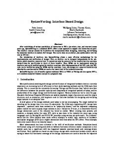
2.3 Design overview The block diagram in Figure 1 shows an overview of the main parts of the TP-UART interface board. The MSP430 MCU is looped into the serial data connection between TP-UART and PC, with its hardware UART to the PC side. The MSP430 is clocked by an external 8 MHz oscillator. For in-system programming and debugging, its JTAG interface is lead onto a pin header that follows the pinout of TI’s “Flash Emulation Tool” JTAG adapters. As a basic local user interface, four LEDs, two DIP switches and two push buttons are connected to general purpose I/O pins of the MSP430.
4
3.3 V Regulator
User interface
External power supply (optional)
JTAG Vcc
RxD / TxD
TP-UART
V+/V-
Vcc
RxD / TxD
MSP430 F123 GPIO
SAVE/TEMP RESET
Push button
Opto-isolation
KNX TP1
Vcc
RxD / TxD
Level conv.
CTS
RTS
Polarity check
DTR
Figure 1: TP-UART interface board connected to KNX TP1 and a PC
The RS-232 serial interface to the PC is terminated by a standard DB-9 female connector. Optocouplers ensure galvanic separation and also handle level conversion for incoming signals. Outbound RS-232 signals go through a low power driver IC (e.g., Maxim MAX1488E). Two signal paths are provided in each direction. They are connected to TXD, RXD, RTS, and CTS. Users have the choice of passing the TP-UART power loss signal (SAVE), its temperature warning output (TEMP), or a MCU general purpose digital output into the PC. The TP-UART outputs are adapted to the optocoupler input characteristics via transistors as on the TP-UART “header board” [7] (designed by Fritz Praus for internal use at the group). If an external power supply is connected, RTS can be used to trigger the MCU and TPUART reset inputs or as an additional input signal for the MCU. The power supply (earth free, stabilized, ±9..15 V) is connected in parallel to DTR and RTS via a 3-pin header. No damage to the PC is expected in case of voltage mismatch between the external power supply and DTR or RTS, as RS-232 line drivers are required to withstand indefinite short-circuit conditions between their output and any other signal conductor. All status pins of the TP-UART are also permanently connected to the MCU, whose firmware can pass their state to the PC via UART communication (this possibility is currently not used). For better monitoring with an oscilloscope or logic analyzer, all TP-UART data and status I/Os (TSTOUT, TxD, RxD, RESn, SAVE) are broken out on a pin header as well. Since the TP-UART and the MCU are powered from the KNX network, they are automatically reset when link power returns after a failure or after being disconnected. In addition, a push button is provided that allows to manually reset both TP-UART and MCU if necessary. Due to its integrated brownout detection, the MSP430 reliably starts up once its power supply is stable. Therefore, a diode protects it from being reset when the TP-UART activates its RESn signal. This increases the time available for firmware initialization, ensuring that the MCU can easily catch the Reset.indication service, which is sent by the TP-UART almost simultaneously with releasing RESn. However, the MSP430 starts up fast enough to correctly receive the service even if the TP-UART is allowed to delay its startup by directly connecting the reset pins.
5
The support circuitry for the TP-UART-IC follows the “typical application circuit” shown in its data sheet. A jumper block determines whether the TP-UART operates in normal mode or in analog mode and connects the required passive components. In normal mode, its host interface is always running at 19200 bps. The MSP430 pins connected to the TP-UART TXD and RXD signals can be directly controlled and used as inputs by the capture/compare-units of the MCU. Thus, accurate timing and efficient operation are possible, both with the TP-UART-IC in normal as well as analog mode. The PCB (printed circuit board) measures 80 x 100 mm. Trace width and spacing are chosen to allow low-cost production. Pin-through-hole components were used wherever possible. The layout also includes mounting holes. However, an enclosure is not required, since all components can be directly mounted on the PCB. All terminals, jumpers, switches, push buttons and LEDs are also labelled there (within the limitations of available space). If the enhanced functionality provided by the microcontroller is not needed, the board can also be assembled without the MCU. This allows immediate use with existing TP-UART related PC software. The PCB layout includes the necessary optional pass-through tracks required for the RXD and TXD lines. The KNX TP1 connector features a dual footprint that allows either headers for standard bus terminals or spring loaded terminals to be mounted.
3 Addressing TP-UART host protocol issues For PC software, keeping time of exactly when a character was received or sent over a serial port is not easy. Often, the available abstractions only offer access to the data stream, without any timing information at all. However, in the TP-UART host protocol, some information is available only by observing the timing of UART character transmissions. The most critical issue concerns end-of-packet (EOP) recognition for frames propagated from the TP1 network to the host. The end of such a received frame is indicated by the TP-UART as a certain (minimum) period of silence on the host interface only. While receiving such a frame, the host must send a U_AckInformation service to the TPUART to indicate if the frame is to be answered by a Layer 2 Acknowledgment frame. While the TP-UART data sheet specifies a deadline for this service, it does not say what will happen if this deadline is not met.
3.1 End of packet indication The challenge is best described by quoting the TP-UART data sheet: “The host controller has to detect an end of packet timeout by supervising the EOP gap of 2 to 2.5 ms” ([1], p. 19). A PC application sitting atop a standard operating system and runtime library has no way of timing external events with such high resolution. An explicit EOP (end-of-packet) indication must therefore be inserted into the data stream. This indication must be clearly recognizable so that it cannot be mistaken as another character received from the network. A break signal (holding the data line in space state for at least a time long enough to send an entire character) leaps to the eye here. A MCU sitting between TP-UART and PC can easily observe the gaps between characters received from the TP-UART. Passing the incoming characters to the PC unaltered, it only needs to insert a break signal whenever it encounters a
6
gap length that exceeds the threshold. The inter-frame gap on the TP1 medium is long enough to easily accommodate the additional time required for indicating the EOP condition on the host interface, especially if the latter is operated at 19.200 bps. This is an elegant solution, since the break signal is an out-of-band signal with respect to the TP-UART host protocol. It is transparent to a host application that ignores break conditions. The protocol is not touched in any way; still, no additional signal line is needed. Unfortunately, not every (software) serial port implementation is able to handle break states. In these cases another method to indicate an EOP condition is required. By using an escape sequence, the indication can be inserted into the character stream itself, achieving maximum compatibility. In our implementation (which also offers signaling by way of break states), the MCU sends the sequence ESC NULL (0x1B 0x00) to the PC to indicate an EOP condition. Any ESC (0x1B) character incoming from the TP-UART is converted into the sequence ESC ESC. If the host interface is operated at 19.200 bps, even incoming frames consisting entirely of ESC characters can still be transmitted with full wire speed. In [1], an EOP gap duration of “2 to 2.5 ms” is given without further comment. Earlier data sheet versions offered “2 to 2.5 bittimes” as well; this has however been corrected. For this project, more detailed information was required. 2,0
⇓
2,0
2,0
>53
Start of Request Frame (⇓)
⇓ Start of repeated L_Request Frame or frame with high priority (⇓) End of L_Data Request Frame (⇓)
>50 ACK, NAK, BUSY
⇓ ⇓
End of L_Poll_Data Request Frame (⇓)
5 ⇓ 5
End of L_Poll_Data Request Frame (⇓) Requester transmits a FILL character
≥ 50
15 Poll-Data
Poll-Data
5
6
Poll-Data
5
Poll-Data
FILL
Poll-Data 5
Figure 2: Inter-character timing on TP1 (adapted from [2]) The situation on the TP1 medium is shown in Fig. 2 (gap times are given in medium bit times of 1/9600 s ≈ 104 µs). “2 to 2.5 ms” correspond to 19 to 24 bit times, which would mean that only the gaps before request frames are considered EOP conditions (with a considerable safety margin). In this case, especially the upper bound could even be relaxed further. If, however, the gaps before any request frame and the gap before an ACK/NACK/BUSY frame are to be considered EOP conditions, but the gaps before Poll-Data or FILL characters are not, an EOP condition can be defined as a gap of seven bit times or longer. This means that an appropriate indication has to be generated whenever there has been silence on the medium for 7×10⁴ µs = 729 µs immediately following the transmission of a character. However, the MCU cannot observe the situation on the TP1 medium directly; it depends on the information it receives from the TP-UART. Therefore, it is important to know how the timing of the characters appearing at the TP-UART host interface reflects the timing of the characters on the medium. While its data sheet does not provide information in this regard, measurements show that the TP-UART appears to propagate characters from the TP1 medium to its host interface with
7
a constant delay of 1.145 ms (from the first edge of start bit on the medium to the first edge of start bit on the host interface).1 The MCU can therefore treat periods of silence between characters (more precisely, the relative time between either start bits or stop bits) received from the TP-UART as a one-to-one representation of the situation on the medium. However, not all characters the MCU receives from the TP-UART have their origin in network traffic. A status character (TP-UART-State.indication/response) can be transmitted spontaneously in case of certain error conditions or in response to a U_State.request by the host controller. In the latter case, the response is usually returned immediately according to our measurements (transmission starts 36 µs after the request has been fully received). Such a request can also be sent while (or immediately before) a frame is received. The TPUART data sheet does not provide information when (or if) the response will be returned in this case. However, measurements show that it is held back until the frame has been completely transmitted to the host.
Figure 3: U_State.request during frame reception (2.00 ms/div, 6.22 ms between cursors) A U_State.request was sent at various time offsets into an ongoing frame reception. One result is shown in Fig. 3. The bottom trace (C3) represents the TP-UART TxD output, the top trace (C4) its RxD input. In all such measurements, the delay measured from the end of the stop bit of the U_State.request (0x02) to the beginning of the start bit of the TP-UARTState.response (0x07) was 6.22 ms. U_AckInformation-Services also sent by the host did not have an influence. Since this delay is far longer than the EOP gap of 729 µs determined above, it is ensured that the TP-UART-State.response cannot be mistakenly interpreted as incoming frame data.
3.2 U_AckInformation timeout condition and handling According to the TP-UART data sheet, the “U_AckInformation-Service is to indicate if the device is addressed. This service must be send latest 1,7 ms (9600 Baud) after receiving the address type octet of an addressed frame” ([1], p. 12). Since no further information is provided, this raises the question why the address type octet is referred to, since the TP-UART does not deal with address interpretation at all otherwise. Also, one would expect a timing constraint that is related to the generation of an acknowledgment frame to refer to the end of the corresponding data frame rather than (an offset from) its 1
All measurements were made using a TP-UART-IC marked as revision “d”, with its host interface configured to operate at 19.200 bps.
8
beginning. In addition, the purpose of specifying a baud rate together with the time period is not obvious. Therefore, measurements were performed to determine the latest possible point in time the TP-UART will accept a U_AckInformation-Service. A stock KNX device was used to generate a standard data frame on the TP1 medium. An MCU was programmed to transmit a U_AckInformation-Service to the TP-UART at a definable time offset after receiving the L_DATA.ind. This offset was successively increased.
Figure 4: U_AckInformation transmission completed in time As shown in Fig. 4, completing the transmission of the U_AckInformation-Service 1.54 ms after the TP-UART has started transmitting the check octet is still fine. The middle trace (C3) represents the TP-UART TxD output, the top trace (C4) its RxD input. Note that the TP-UART still puts an acknowledgment frame onto the bus (bottom trace, difference signal between the two TP1 conductors). Actually, the U_AckInformation-Service could not arrive any later, since the acknowledgment frame has to appear on the TP1 medium exactly 15 bit times after the data frame (cf. Fig. 2). Indeed, if the U_AckInformation-Service is sent 64 µs later, the TP-UART no longer generates an acknowledgment frame (Fig. 5). The sender repeats its transmission three times (not shown in Fig. 5), which means that the U_AckInformation-Service was ignored rather than stored. The TP-UART continues ignoring received U_AckInformation-Services until it has transmitted the next L_DATA.ind. Fig. 6 summarizes the measurements as a sequence diagram, indicating the time slot where the U_AckInformation-Service has to be sent to the TP-UART. The frame used in these experiments is the shortest possible standard frame containing User-Data (in this case, one Bit). However, a transport layer PDU (e.g., for connection man-
9
Figure 5: U_AckInformation transmission completed too late
agement purposes) may be one octet shorter still. If a sequence similar to Fig. 6 is considered for such an 8-octet frame and a host interface data rate of 9.600 bps, it turns out that the latest possible moment to start sending the U_AckInformation-Service so that it still reaches the TP-UART in time is quite precisely 1.7 ms after the destination address type/hop count/length octet has been completely received. Very probably, the sentence in the TP-UART data sheet quoted at the beginning of this section refers to this worst-case situation. It can be assumed that the findings can be also be applied to longer frames than the one tested. Strictly speaking, however, the relaxed response time requirement is an undocumented feature, and no claim can be made about the TP-UART in general. Before relying on it, the time slot allowed by the actual TP-UART chip to be used should be checked. A frame of the maximum expected length must be created on the bus (e.g., using ETS), the MCU programmed to generate the U_AckInformation-Service at the latest point in time as specified above, and the network monitored if an acknowledgment frame is sent by the TP-UART. Also, it must be considered that when a MCU is placed between the TP-UART and the PC to monitor this time slot, the constraints described apply to its TP-UART side. The maximum allowable response time for the PC is shorter due to the transmission delays between MCU and PC and processing delay in the MCU. With the precise timing requirements for sending acknowledgment information defined, the question remains how to react when the PC does not meet them. The MCU could of course easily generate a U_AckInformation-Service itself. However, if the interface is to be as transparent as possible (and, thus, stateless), the MCU has no way of knowing if the received frame
10
KNX bus 0
TP-UART
Host Controller
Control Field L_Data.ind Source Address U_AckInformation
2
(earliest)
Source Address Source Address
Source Address 4
Destination Address
Destination Address Destination Address 6 Destination Address DAF, Hop Count, Length
8
DAF, Hop Count, Length Data
Data Data 10 Data Check Octet
Check Octet
12
U_AckInformation
(latest)
Acknowledge Frame 14
16
t [ms]
Figure 6: Time frame for U_AckInformation
contained a destination address handled by the PC. Therefore, none of the possible acknowledgment frames (ACK, NACK, BUSY) is appropriate from a semantic point of view. Not sending an acknowledgment frame, on the other hand, leaves the reason why a node could not find any of its addresses in the received frame open: It may have been because the frame had another destination, but it may also have been because the destination information was destroyed by a transmission error. In the case of our interface, it may also have been because access to the node addresses could not be provided in time. Thus, the current MCU firmware does not send U_AckInformation-Services by itself. This can easily be changed if a different behaviour appears more appropriate. In particular, one may choose to focus on the effect caused by the different types of acknowledgment frames (or absence thereof): The receiver can send BUSY/NACK to force the sender to retransmit unconditionally (up to the maximum number of repetitions); send ACK to suppress repetitions unless explicitly requested by another node (of the same group) via BUSY/NACK; or remain silent, causing a retransmission unless another node sent ACK. Since the PC application will usually have a large enough buffer to hold – and eventually process – all incoming frames, causing a frame to be sent again probably does more harm than good. Thus, having the MCU cause the transmission of an ACK frame by default may be an alternative worth considering. Actually, couplers do a similar thing when they acknowledge an incoming frame although they cannot know for certain if they will be able to re-send it via the other interface. Unless an ACK frame is sent by default, a frame retransmission is to be expected when the PC fails to meet the U_AckInformation deadline. The MCU could store the late U_AckInformation
11
and apply it to the repeated transmission. However, it is hard to see a possible benefit of such a strategy: If the PC is usually fast enough, it should be able to create the U_AckInformation for the repeated L_DATA.ind itself; if it often fails to meet the deadline, but its message buffer is large enough and its average processing capacity sufficient to prevent the buffer from overflowing, sending ACK frames by default seems to be a better solution since it avoids the retransmissions on the network; finally, if its message buffer size and average processing capacity are insufficient, it is very questionable if the time bought by additional retransmissions will have any positive effect at all. On the other hand, implementing this strategy obscures the protocol interface. Also, to be safe, this would not be a matter of only checking the repeat flag, but entire frames would have to be stored and compared. Therefore, the current implementation (like the TP-UART) suppresses late U_AckInformation-Services until it has transmitted the first character of an incoming frame (L_DATA.ind). In any case, such a timeout situation is best avoided on the PC side. It is therefore essential to inform the user when a timeout has occurred. In the current implementation, this is done by displaying the timeout count via the LEDs on the interface (freezing at the highest number that can be represented in case of overflow).
4 The TP-UART host protocol: Further insights While the motivation for this project certainly was to find a way of working around the timing issues during frame reception, the necessity of dealing with the TP-UART host protocol in detail also led to some insights on protocol aspects not immediately related to this problem.
4.1 Reaction to corrupted service requests The TP-UART-State.Indication-Service (as described in the TP-UART data sheet) contains “protocol error” and “receive error” flags. However, the conditions that would provoke such error indications are not revealed. In order to shed some light on this, selectively corrupted service requests were sent to the TP-UART. All of them were based on the same short standard data frame (in the following, all data are shown in hexadecimal): BC 11 01 09 01 E1 00 81 3B If this frame is to be transmitted via the TP-UART, the required host protocol services have to be added. The inserted characters are ‘80’ (U_L_DataStart), ‘81’ ... ‘87’ (U_L_DataContinue) and ‘48’ (U_L_DataEnd). 80 BC 81 11 82 01 83 09 84 01 85 E1 86 00 87 81 48 3B Since this is a correct service request, the TP-UART transmits the frame on the TP1 network and receives it the same time, propagating it back to the PC: BC 11 01 09 01 E1 00 81 3B 8B Its output is identical with the original KNX frame. An L_Data.confirm Service with the “successful” flag set (8B) is appended, indicating a successful transmission. A corrupted check octet is answered with a TP-UART-State.Indication-Service with the “receive error” flag set (in the following, characters that are different from the initial example are underscored):
12
TO TP-UART: 80 BC 81 11 82 01 83 09 84 01 85 E1 86 00 87 81 48 3C TO H OST : 47
The TP-UART also indicates a receive error when its RxD input remains silent for about 3 ms after a U_L_DataStart service (80). If the request is sent with its control byte being corrupted, the TP-UART returns two State.IndicationServices, with the protocol error flag set in the first (17) and the receive error flag set in the second one (47). TO TP-UART: 80 7C 81 11 82 01 83 09 84 01 85 E1 86 00 87 81 48 3B TO H OST : 17 47
Figure 7: Corrupted control byte producing error indications Fig. 7 shows the corresponding waveforms (top: TP-UART RxD, bottom: TP-UART TxD). An interesting detail to see is that the protocol error is generated immediately after the receipt of the corrupted control byte. The receive error is generated after receiving the check octet (possibly due to the mismatch caused by not adapting the check octet to match the altered frame). The count field of the U_L_DataContinue services separating the KNX frame bytes must be successively incremented by one. If this condition is violated, no error indication is given. Rather, the content of the KNX frame is altered: TO TP-UART: 80 BC 81 11 82 01 BE 09 81 01 81 E1 81 00 81 81 48 3B TO H OST : BC 81 01 09 01 E1 00 81 AB 8B
Although the host can detect the error condition by comparing the intended frame data with those echoed back by the TP-UART, the changed frame has already been transmitted on the network. This is acknowledged by an L_Data.confirm service (8B). Surprisingly, the wrong check octet does not cause an error but is modified as well. The penultimate byte sent to the TP-UART is the U_L_DataEnd service. In case this one is corrupted, the TP-UART adapts the frame length according its new value. In this example, its count field is increased by one. In the resulting KNX frame one byte is inserted and the checksum is adapted by the TP-UART. A positive L_Data.confirm service is returned. TO TP-UART: 80 BC 81 11 82 01 83 09 84 01 85 E1 86 00 87 81 49 3B TO H OST : BC 11 01 09 01 E1 00 81 22 19 8B
Likewise, if the count field is increased by seven, seven bytes are inserted. Again, successful transmission is indicated by a L_Data.confirm service. TO TP-UART: 80 BC 81 11 82 01 83 09 84 01 85 E1 86 00 87 81 4F 3B
13
TO H OST : BC 11 01 09 01 E1 00 81 22 FF A8 F7 59 FF D0 CF 8B
However, the count field of U_L_DataEnd cannot be increased without limits. Its maximum value is 7F, which corresponds to the 64 octets telegram send buffer of the TP-UART. If this value is exceeded (in the following example, it is set to 80), the TP-UART indicates a protocol error. TO TP-UART: 80 BC 81 11 82 01 83 09 84 01 85 E1 86 00 87 81 80 3B TO H OST : 17
It would also be interesting to know how the TP-UART deals with faulty frames received from the network (e.g., containing wrong check octets, timing violations, or parity errors). Although suitable hardware (TP-UART in analog mode) is available, this was not yet possible within the scope of this project for organizational reasons.
4.2 Reset behaviour After power-up and following a “warm start” in response to a U_Reset.request (0x01), the TPUART transmits a TP-UART-Reset.indication (0x03). However, 0x3F or even nothing at all is often received instead. This can be explained by examining closely what happens on the TPUART TxD output. In normal mode, TxD is High when idle. On power-down, TxD falls Low. On power-up, TxD and RESn are kept Low until Vcc has stabilized. TxD goes back to idle level approximately 5 ms after RESn has been released (Fig. 8).
Figure 8: TP-UART power up Upon reception of a U_Reset.request service, TxD immediately falls Low. This state persists for 5.4 ms. Fig. 9 shows the corresponding waveforms (top: TP-UART RxD, bottom: TP-UART TxD).
14
Figure 9: TP-UART software reset (2.00 ms/div)
In both cases, TxD remains Low for an extended period of time. This corresponds to a break condition. Depending on the PC configuration, this is often propagated to the application as 0x00. The TP-UART-Reset.indication is transmitted immediately following this long break state, with TxD rising to idle state only for a single bit time (Fig. 10). If the serial port handling code on the PC “wakes up” too late, this character can be lost or distorted. For example, if the penultimate data bit is interpreted as a start bit and parity checking is deactivated, the application may see 0x3F instead.
Figure 10: TP-UART-Reset.indication (500 µs/div)
5 Summary and outlook The TP-UART host interface protocol requires precise timekeeping to detect an end-of-packet condition and quick reaction if acknowledgment frames are to be sent. Closer examination reveals that U_AckInformation services may in many circumstances be sent significantly later than the TP-UART data sheet specifies. Moreover, protocol properties with regard to error handling were demonstrated that may be considered unexpected. Strategies for handling end-of-packet indication and U_AckInformation timing constraints to make the TP-UART host protocol suitable for PCs have been discussed. They rely on a microcontroller sitting between TP-UART and PC. This microcontroller, however, only minimally interferes with the original protocol. The strategies were implemented and tested using a small
15
TI MSP430 family microcontroller. Existing PC applications can be adapted with minimum effort. Future versions of eibd [12] will also provide support for the enhanced protocol. A KNX PC interface based on this microcontroller and the TP-UART was presented. Its versatile design allows it to be used for tasks far beyond the scope of this project. It has already been tested. Its design will be made openly available. The PCB was designed using the EAGLE Layout Editor. Since the PCB dimensions do not exceed 80 × 100 mm, changes can be made using EAGLE Light Edition, which is distributed free of charge for non-commercial and evaluation purposes. The toolchain required to program the used microcontroller is available without cost as well. A test and demonstration program for the PC side was created as well. It uses termios to access the serial port and can be compiled using GCC without changes on both Linux and Windows/Cygwin. It allows to send and decode TP-UART host protocol services and can – of course – deal with the end-of-packet indication methods described previously. It also provides access to the RS-232 DTR, RTS and CTS signals. Like the microcontroller firmware, it will be made available as open source. The interface hardware allows many further ideas to be implemented. For example, escape sequences could be used to carry basically any information to the PC, including the SAVE signal. The MCU may be used to improve error handling or could delay the TP-UARTReset.indication for slow PC serial port implementations. A USB version could easily be created by replacing the level conversion/parasitic power supply circuitry with an integrated USB to UART chip. Until then, stock USB to RS-232 converters can be used.
References [1] Siemens EIB-TP-UART-IC Technical Data, http://www.automation.siemens.com/et/gamma/download/tpuart.pdf [2] KNX Handbook, Vol. 3, Part 2, Ch. 2, System Specifications: Communication Media: Twisted Pair 1, v1.0 AS [3] Schematic of the Siemens-TPUART-interface for the serial port, http://os-projects.fh-deggendorf.de/images/tpuart-interface.png (retrieved in November 2001, no longer available online) [4] TP-UART interface by C. Troger, https://www.auto.tuwien.ac.at/downloads/eib4linux/tp-uart-interface.zip [5] Disch Systems TP-UART Interface, http://disch-systems.de/download/tpuart_interface_en-datasheet.pdf [6] Siemens Bus Transceiver Module PCB Technical Data, http://www.opternus.com/uploads/media/BTM_PCB_datasheet_V2.0.pdf [7] F. Praus, W. Kastner and G. Neugschwandtner, “A versatile networked embedded platform for KNX/EIB”, KNX Scientific Conference 2006, Vienna.
16
[8] R. Stocker and A. Grzemba, “Linux Device Driver for the TP-UART interface”, EIB Scientific Conference, October 2001, Munich. [9] W. Kastner and C. Troger, “Interfacing with the EIB/KNX: A RTLinux device driver for the TPUART”, Proc. 5th IFAC Intl. Conference on Fieldbus Systems and their Applications (FeT ’03), pp. 29–36, 2003. [10] TP-UART Linux kernel driver updates by R. Buchinger and M. Kögler, https://www.auto.tuwien.ac.at/a-lab/eib4linux.html [11] Disch Systems EIB Driver for Linux, http://disch-systems.de/download/edrv_en-datasheet.pdf [12] eibd daemon homepage, http://www.auto.tuwien.ac.at/~mkoegler/index.php/eibd [13] United States Patent 7,291,938, “Power supply apparatus and method based on parasitic power extraction”, 2007. [14] TI MSP430x12x Mixed Signal Microcontroller (Rev. C) Datasheet, http://www.ti.com/lit/gpn/msp430f123 [15] TI MSP430F11x2, MSP430F12x2 Mixed Signal Microcontroller (Rev. D) Datasheet, http://www.ti.com/lit/gpn/msp430f1232 [16] TI MSP430x1xx Family User’s Guide (Rev. F), http://www.ti.com/litv/pdf/slau049f All online references last accessed October 2008, unless otherwise noted.
17