Microcontroller Based Interface Design. System Engineering the Rover. Study of
Microprocessor Based Systems and their integration with peripheral devices.
Microcontroller Based Interface Design Part 1 System Engineering the Rover
Study of Microprocessor Based Systems and their integration with peripheral devices including sensors, actuators, and serial communications. Programming problems will be completed in C++, and at the instructor’s discretion assembly, using the basic problem solving techniques learned in CECS100 and EE346. Following a progressive lab sequence, over the semester the student will design and construct a modern RISC microcontroller based system. EE444 “Study of RISC microprocessor based systems and their integration with peripheral devices” Course Description
1
1
Microcontroller Based Interface Design
1.1
Embedded Systems
Figure 1.0
Controller Based System
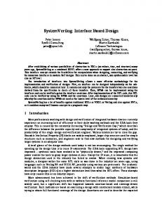
Engineers design systems. A system can be characterized by a box with an input and output. Typically the engineer is tasked to design the box with a given set of inputs and a desired output. ●
When a controller “the brain” is part of the design solution, the design is known as an Embedded System. ● The controller may be implemented using an ASIC (Application Integrated Circuit), FPGA (Field Programmable Gate Array) or in most cases a Microcontroller. ● For a microcontroller based design, the input device is by definition a Sensor, while the output device is known as an Actuator. In this document we look at the microcontroller based system design used by our rovers. It is hoped that by looking at this specific example you will be able to apply the lessons learned to the design of other microcontroller based systems.
2
1.2 Figure 1.1
Rover Microcontroller Based System Design ATmega328P Microcontroller Based System
Figure 1.1 illustrates our rover design from a generic capabilities perspective. At the heart of our embedded system is an Atmel ATmega328P Microcontroller.
3
The ATmega328P is built into an Arduino motherboard.
Figure 1.2 ● ● ● ● ● ●
1.3
Arduino Uno
The Arduino is an Open-source Development Platform. The Arduino board provides power conditioning, and a 16 MHz system clock. The Arduino in addition provides a C++ IDE (Integrated Development Environment) for writing your program. Once your program is written, the Arduino provides a Boot Loader, running in firmware, and USB (Universal Serial Bus) communications circuitry for uploading your programs and downloading data. Finally, the Arduino board includes two sets of connectors for plugging in a daughter-board called a Shield. Our rovers includes the Adafruit Motor Shield. The Adafruit motor shield extends the capability of the Arduino by adding two L293D H-Bridge ICs. The L293D H-Bridge IC can provide 0.6 A per bridge (1.2A peak) to run our motors.
Document Objective
The objective of this document is to teach you how to interface peripheral devices to a microcontroller based system. We first... 1. define the resource capabilities of our integrated system (ATmega328P - Arduino Adafruit Motor Shield), next 2. look at how sensors and actuators could be incorporated into this design and finally 3. present the reference design as an example.
2
Interface Capabilities of our Integrated System
Our embedded system is comprised of an ATmega328P, Arduino Board, and Adafruit Motor Shield. As shown in Figure 1.1, at the heart of the system is the ATmega328P microcontroller. Both the Arduino and the Adafruit motor shield consume some of the resources of the ATmega328P in exchange for extending the capabilities of the integrated system. Table 2 provides a mapping of these resources and ultimately (last column) the interface resources
4
available to the sensors and actuators of our rover. Table 2.0 System Resource Map ATmega328P
Arduino
Motor Shield
Motor Shield DIR (SPI Interface)
Motor Shield PWM (H-Bridge & Servos)
Rover
1
PD0 (RXD)
J1-1 Digital Pin 0
2
PD1 (TXD)
J1-2 Digital Pin 1
3
PD2 (INT0)
J1-3 Digital Pin 2
JP3 Pin 1
4
PD3 (INT1, OC2B)
J1-4 Digital Pin 3
PWM2B
5
PD4 (T0)
J1-5 Digital Pin 4
DIR_CLK
6
PD5 (T1, OC0B)
J1-6 Digital Pin 5
PWM0B
IC2 Pin 1 (1-2)EN
7
PD6 (OC0A, AIN0)
J1-7 Digital Pin 6
PWM0A
IC2 Pin 9 (3-4EN)
8
PD7 (AIN1)
J1-8 Digital Pin 7
DIR_EN
9
PC0 (ADC0)
J2-1 Analog Pin 0
JP5-1
Long Range IR
10
PC1 (ADC1)
J2-2 Analog Pin 1
JP5-2
Mid Range IR
11
PC2 (ADC2)
J2-3 Analog Pin 2
JP5-3
12
PC3 (ADC 3)
J2-4 Analog Pin 3
JP5-4
13
PC4 (ADC 4, SDA)
J2-5 Analog Pin 4
JP5-5
Gyro I2C SDA
14
PC5 (ADC 5, SCL)
J2-6 Analog Pin 5
JP5-6
Gyro I2C SCL
15
PB0 (ICP1)
J3-1 Digital Pin 8
DIR_SER
16
PB1 (OC1A)
J3-2 Digital Pin 9
PWM1A
Servo 2 Signal
17
PB2 (SS, OC1B)
J3-3 Digital Pin 10
PWM1B
Servo 1 Signal
18
PB3 (MOSI, OC2A)
J3-4 Digital Pin 11
PWM2A
IC1 Pin 1 (1-2EN)
Laser
IC1 Pin 9 (3-4EN) IC3 Pin 11 (SCK)
IC3 Pin 13 (G)
IC3 Pin 14 (SER)
5
Servo Yellow or Orange Wire
19
PB4 (MISO)
J3-5 Digital Pin 12
20
PB5 (SCK)
J3-6 Digital Pin 13
21
GND
J3-7 GND
22
AREF
J3-8 AREF
DIR _Latch
IC3 Pin 12 (RCK)
GND 4.7 K to 3.3v
23
X1-P1 (M1)
Left DC Motor -
24
X1-P2 (M1)
Left DC Motor +
25
X1-P3 (GND)
NC
26
X1-P4 (M2)
Right Motor -
27
X1-P5 (M2)
Right Motor +
28
X2-P1 (M4)
Stepper Motor Red
29
X2-P2 (M4)
Stepper Motor Blue
30
X2-P3 (GND)
NC
31
X2-P4 (M3)
Stepper Motor Black
32
X2-P5 (M3)
Stepper Motor Green
6
2.1
ATmega328P I/O pins (column 1)
The I/O pins of the the ATmega328P are shown in column 1 of Table 2.0. Due to pinout limitations of the IC package (DIP, TQFP, and QFN/MLF), ● ●
all I/O pins of the ATmega328P are multiplexed. Specifically, they can be programmed to provide different interfaces to the system.
Figure 2.0
ATmega328P Pin-out
2.1.1 XTAL and Reset Shown in Figure 2.0 but not Table 2.0 is the loss of three digital I/O pins for the XTAL (crystal) and reset. What this means to the system designer instead of having 23 digital pins he/she now only has twenty (20).
2.2
Arduino (column 2)
The multiplexing of the I/O pins immediately forces the system engineer to make trade-offs in the design of their device. For example, as shown in the first two rows of Table 2.0, to allow communications with a PC, the Arduino uses the pins allocated to the USART0 (Univeral Asynchronous Receiver/Transmitter) peripheral subsystem of the ATmega328P. These pins are shared (multiplexed) with the GPIO (General Purpose Input/Output) peripheral subsystem of the ATmega328P subsystem. In Table 2.0, this loss of resources to the rover is shown by the color of the cells going from light orange to white. For completeness, it should be noted that in a pinch some of these resources can be recovered, but at the cost of system complexity.
7
Table 2.1
Multiplexed GPIO Pins Lost to ATmega328P Subsystems
GPIO Port D bits 1 and 0 Port B bits 7 and 6 Port C bit 6
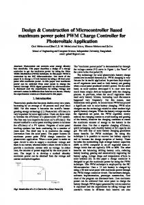
Figure 2.1
ATmega328P Subsystem Function USART 0 Oscillator Circuits / Clock Generation Power Supervision POR / BOD & Reset
ATmega328P Simplified Block Diagram
8
2.3
Adafruit Motor Shield
The Adafruit motor shield conserves microcontroller resources by implementing an SPI (Serial Peripheral Interface) interface in software. Thus, while the motor shield requires 8 digital pins to configure the two L293D Dual H-Bridge ICs, it only uses four (4) ATmega328P general purpose I/O pins. In addition, the motor shield requires four (4) PWM (Pulse Width Modulation) pins. Thus our ATmega328P GPIO pin count has been further reduced from eighteen (18) to ten (10). Table 2.2
Multiplexed GPIO Pins Used by Adafruit Subsystems
GPIO Port D bits 7, 4 and Port C bits 4, 0 Port D bits 6, 5, 3 and Port B bit 3
Adafruit Subsystem Function Digital Input Register (DIR) 74HCT595N 2 x L293D Dual H-Bridge
In exchange for the loss of eight (8) ATmega328P GPIO pins, the Adafruit motor shield now provides 4 H-bridges outputs (plus two ground pins) - Table 2.0 rows 23 to 32.
2.4
Rover Resource Map
Table 2 Rover Resource Map shows the 10 I/O pins available to the rover. In the next section we look at how sensors and actuators could be incorporated into the design of our rover. Specifically, we will map our I/O pins to our sensors and actuators Table 2.3 Up To 6 10 10 2 4 1
Rover Resource Summary I/O Pin Names Analog (ADC0 to ADC5) GPIO (PC5-0, PB5, PB2, PB1, PD2) GPIO (PC5-0, PB5, PB2, PB1, PD2) PWM (PWM1A, PWM1B) H-Bridge Channels (M1, M2, M3, M4) Serial Interface (SDA, SCL)
Sensor/Actuator Type Analog Sensors Digital (on/off) Sensors Digital (on/off) Actuators PWM Controlled Motors1 Bi-Directional PWM Controlled Motors I2C Sensors and/or Actuators
Notice that the I/O Types in Table 2.3 add up to more than ten (10), which brings us back to the beginning. Specifically, the system engineer must now trade off these 33 possible interface types with the 10 remaining pins available to them.
1
Technically, the total number of PWM channels is 6 (4+2), if you chose to use the 4 Bi-Directional channels as single PWM channels.
9
Table 2.3
Rover Resource Map
ATmega328P
Arduino
Motor Shield
3
PD2 (INT0)
J1-3 Digital Pin 2
JP3 Pin 1
9
PC0 (ADC0)
J2-1 Analog Pin 0
JP5-1
10
PC1 (ADC1)
J2-2 Analog Pin 1
JP5-2
11
PC2 (ADC2)
J2-3 Analog Pin 2
JP5-3
12
PC3 (ADC 3)
J2-4 Analog Pin 3
JP5-4
13
PC4 (ADC 4, SDA)
J2-5 Analog Pin 4
JP5-5
14
PC5 (ADC 5, SCL)
J2-6 Analog Pin 5
JP5-6
16
PB1 (OC1A)
J3-2 Digital Pin 9
PWM1A
17
PB2 (SS, OC1A)
J3-3 Digital Pin 10
PWM1B
20
PB5 (SCK)
J3-6 Digital Pin 13
23
X1-P1 (M1)
24
X1-P2 (M1)
25
X1-P3 (GND)
26
X1-P4 (M2)
27
X1-P5 (M2)
28
X2-P1 (M4)
29
X2-P2 (M4)
30
X2-P3 (GND)
31
X2-P4 (M3)
32
X2-P5 (M3)
Motor Shield DIR
10
Motor Shield PWM (H-Bridge)
Rover
2.4.1 Notes 1. Table 2.3 does not include pins associated with ATmega328P subsystems considered outside the scope of this document, for example:the analog comparator. 2. As discussed in the document, the Adafruit motor shield implements the SPI interface in software. Unfortunately, other design trade-offs make the SPI subsystem of the ATmega328P inaccessible to the Rover. This design decision was made by Adafruit in order to maximize the number of PWM channels available to the system. 3. Technically the L293D is a quadruple half-h driver. However, Adafruit has wired them in a dual H-Bridge configuration. Specifically, two enable lines are wired to a single PWM channel.
11