Design of An Online Tuning Modified-Grey Fuzzy PID Controller for Nonlinear Systems Dinh Quang Truong*, Kyoung Kwan Ahn*, Jong Il Yoon*, Maolin Jin**, Chin Tae Choi** *
School of Mechanical and Automotive Engineering, University of Ulsan, Ulsan, South of Korea
[email protected];
[email protected] ** Research Institute of Industrial Science and Technology, Pohang, South of Korea
Abstract: This paper presents a design of a novel adaptive controller - online tuning modified-Grey fuzzy PID (OTMGFPID) - to deal with nonlinear systems. The OTMGFPID is a combination of a main control unit - online tuning fuzzy PID (OTFPID), and a predictor online tuning modified-Grey predictor (OTMGP). The OTFPID controller, which is built from an adaptive proportional-integralderivative (PID) controller based on an online tuning fuzzy-neural technique and robust checking conditions, is used to drive the system to desired targets. In addition, a smart learning mechanism (SLM) was implemented into the OTFPID in order to optimize smartly its parameters with respect to the control error minimization. The OTMGP with online tuning ability of the predictor step size based fuzzy (FPSS) is used to estimate the actual system output and to create a compensating signal corresponding to the system perturbations. The effectiveness of the proposed OTMGFPID controller has been evaluated by numerical simulations in a comparison with other typical controllers. Keywords: fuzzy, PID controller, modified-Grey predictor, smart online tuning, nonlinear system
I.
INTRODUCTION
Nowadays, automation in control has been applied more and more in the modern life. However, most of industrial machines are nonlinear systems of which the control has been a challenging and yet rewarding problem. Conventional PID controllers are commonly used in industry due to their simplicity, clear functionality and ease of implementation. Meanwhile, fuzzy control, an intelligent control method imitating the logical thinking of human and being independent on accurate mathematical model of the controlled object, can overcome some shortcomings of the traditional PID. But the fuzzy is a nonlinear control and the output of the controller has the static error [1]. Then fuzzy PID control which combines the traditional PID control and the fuzzy control algorithm is a solution ([1, 2]). However, the typical fuzzy PID controllers are experimentally designed based on working conditions of the control systems and their dynamic responses ([5]). Hence, the typical fuzzy PID controllers cannot adapt for a wide range of working environments with large variation of perturbations ([6]). As a result, other control techniques such as robust control, intelligent theory, or estimation methods are needed to combine with the fuzzy PID to overcome this weakness ([3-8]). Among them, fuzzy PID combined with neural network and Grey predictive techniques is a feasible solution. The concept of “Grey systems” was first proposed by Deng [9] to deal with systems that have partially unknown parameters. The Grey
978-1-4244-8452-2/11/$26.00 ©2011 IEEE
prediction technique has been successfully employed to solve many engineering problems ([8-12]). The aim of this paper is to develop a novel adaptive control method which is called online tuning modified-Grey fuzzy PID to improve performances of nonlinear systems. The OTMGFPID control system is constructed from the main control unit, online tuning fuzzy PID based on neural network, and the online tuning modified-Grey predictor which was developed from the typical single variable first order Grey prediction model GM(1, 1). During the operation, an observation of the previous system output values is fed into the OTMGP to estimate the output in the near future differing from the present p sampling times which is called the fuzzy predictor step size. This step size is online tuned by two fuzzy sets corresponding to the control error. The predicted system output is then fed into the OTFPID controller to create a control input for the system. In addition, an additive correction to the control signal is produced by the OTMGP to compensate for the disturbances. At the same time, input and output MFs of the fuzzy structure inside the OTFPID are smartly optimized online with respect to the control error minimization by using the smart learning mechanism while the PID gains are updated through the robust checking conditions, consequently, improving the control quality. Numerical simulations for a nonlinear system plan using some typical controllers and the designed controller has been done in order to verify the ability of the proposed control methodology. II.
OTMGFPID CONTROLLER DESIGN
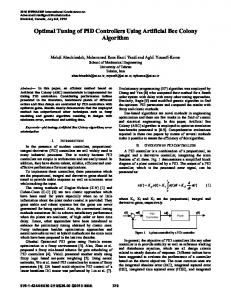
Overall control structure of the online tuning modifiedGrey fuzzy PID controller is depicted in Fig. 1. It is constructed from two building blocks: + The online tuning fuzzy PID controller - OTFPID + The online tuning modified-Grey predictor - OTMGP yr ( t ) e ( t )
um ( t )
N (t ) u (t )
D (t )
y (t )
uc ( t )
yr ( t + p )
yˆ ( t + p )
yr ( t )
Figure 1. A nonlinear system using proposed OTMGFPID controller
FPM 2011 481
The OTMGP is to estimate the system actuation in the near future, yˆ ( t + p ) , on which the OTFPID bases to generate the
control input signal, uOTFPID ( t ) ≡ um ( t ) , for the system to follow a desired target. Moreover, the OTMGP also produces an amount of control signal, uOTMGP ( t ) ≡ uc ( t ) , to compensate for the system noises and disturbances. The system control signal is computed uOTMGFPID ( t ) ≡ u ( t ) = um ( t ) + uc ( t )
(1)
A. Online Tuning Fuzzy PID Controller The control problem is considered for a system with single input and single output. The main control signal of system using a conventional PID controller can be expressed as: t
um ( t ) ≡ uPID ( t ) = K P e ( t ) + K I ³ e ( t ) dt + K D 0
de ( t ) dt
(2)
where: e(t) : the error between the desired set point and system response; de(t): the derivation of error e(t); um = uPID(t): the main control signal; KP, KI, and KD: the proportional gain, integral gain, and derivative gain of PID controller, respectively. These coefficients were designed to be tuned by using separate fuzzy tuners, fuzzy P, I and D, respectively. K A = K A0 + U A ΔK A , U A ∈ [ 0,1] , ( A is P, I or D )
(3)
where: UA: the parameter obtained from fuzzy A tuner; ΔK A = K A1 − K A 0 : the allowable deviation of KA ; K A 0 , K A1 : the minimum, maximum values of KA. For robust control approach, there are two control objectives. The first is close-loop robust stability which must be checked with reasonable margins. The second control objective is close-loop disturbance attenuation [7]. From (2), transfer function of the PID controller as well as the system open-loop transfer function and the sensitivity function are expressed as: 1 + KD s s L ( s ) = P ( s ) G PID ( s )
GPID = K P + K I
S ( s) =
1 1+ L ( s)
(4) (5)
(6)
Based on the robust control criteria, the PID controller gains can be derived. For the robust stability, an approximately minimal value of M = 1.4 (3 dB) gain margin for the close-loop system is given by:
L ( s)
1+ L (s)
≤ M = 1.4
(7)
For the disturbance rejection requirement, the general upper bound of the sensitivity is set to limit the peak value of disturbance amplification as follows: 1 ≤ MD,MD >1 1 + L ( s ) max
(8)
At a working step, the fuzzy tuners produce a set of PID gains corresponding to the system control error. To ensure that the controller can drive the system to satisfy the robustness specifications, the PID gains are updated for each working step of time (t+1)th based on a following rule: ª K A ( t + 1) using ( 3) IF : satisty ( ( 7 ) & ( 8 ) ) K APID ( t + 1) = « otherwise «¬ K A ( t )
(9)
There are same two inputs to both the three fuzzy tuners as absolute scales of the controlled system error e* ( t ) and its derivative de* ( t ) which are forced into a same range from 0 to 1 by using suitable gains. For all of the fuzzy designs, triangle membership functions (MFs) are used. The fuzzy reasoning results of outputs are gained by aggregation operation of fuzzy sets of inputs and designed fuzzy rules, where max-min aggregation method and centroid defuzzification method are used. For each of the fuzzy P/I/D input variables, their MFs can be expressed as follows:
( xi − aij ) °1 + if ( −bij− ) ≤ ( xi − aij ) ≤ 0 − b ° ji ° ° ( xi − aij ) f j ( xi ) = ®1 − if 0 ≤ ( xi − aij ) ≤ ( bij+ ) ; + b ij ° °0 otherwise ° ° ¯ i = 1, 2; j = 1, 2,..., N
(10)
where: xi is an input value; aij , bij− , bij+ , and N are the centroid, left half-width, right half-width of jth MF, and MF number of the ith input, respectively. Each of the fuzzy P, I and D tuners has one output: M
¦ mf ( w ) w m
U FA =
m =1 M
¦ mf ( wm )
m
, ( A is P, I or D )
(11)
m =1
where: wm is the weight of the control output (the centroid of the mth MF of the fuzzy a output); M is the MF number; and mf ( wm ) is the fuzzy output function
482
mf ( wm ) = ¦ mf jk ( wm )
(12)
j ,k
yr ( t )
where mf jk ( wm ) is defined as the consequent fuzzy output function when the first and second inputs are in the jth and kth classes, respectively mf jk ( wm ) = δ jk μ jk
x1 is in class jth, and input x2 is in class kth; μ jk is the height of the consequent fuzzy function obtained from the input class jth and kth
(14)
The output UFA of the tuning fuzzy controller contains single output values which are initially set at the same intervals. Consequently, the parameter UA in (3) can be obtained from the fuzzy tuner outputs, UFA, by using sigmoid activation function UA =
1 , U A ∈ ( 0,1) , ( A is P, I or D ) 1 + e −U FA
(15)
By using equations from (3) to (15), the main control signal using the designed controller can be computed from (2). The structure of fuzzy PID controller is adjusted in advance to minimize the control error function. E (t + p ) =
2 1 ª yˆ ( t + p ) − yr ( t + p ) ¼º 2¬
(16)
where: yr ( t + p ) and yˆ ( t + p ) are in turn the reference input for control task of the system (or named the target value) and the estimated system output in a near future which differs from the present time p steps of sample time. The learning mechanism is based on gradient descent method and back propagation algorithm to tune the decisive factors of fuzzy input MFs a j , b −j , b +j and output weights wm
∂Et + p ° a j (t +1) = a jt − η a ∂a jt ° ° ∂Et + p ° +/− +/− ®b j ( t +1) = b jt − ηb + / − ∂b jt ° ° ∂Et + p °w = wmt − η a m ( t +1) ∂wmt ¯°
yˆ ( t )
(13)
where: δ jk is a activated factor, which is active when the input
μ jk = min ª¬ f j ( x1 ) , f k ( x2 ) º¼
y (t )
yˆ ( t + p )
eND ( t )
eˆND ( t + 1)
uOTMGP ( t ) ≡ uc ( t )
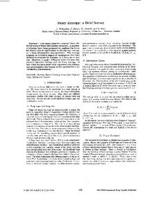
Figure 2. Structure of the OTMGP predictor
B. Online Tuning Modified-Grey Predictor The OTMGP structure is shown in Fig. 2. The OTMGP contains two inputs - the desired yr(t) and actual system responses y(t) - and two outputs - the estimated system response in the near future yˆ ( t + p ) and an amount of compensating control signal uOTMGP(t). Based on the observation of system responses, the first modified-Grey model first order-one variable (MGM1(1,1)) with dynamic FPSS estimates the system response in the near future, yˆ ( t + p ) , which is sent to the main control unit to perform the control signal. At the same time, the MGM1(1,1) also carries out the predicted system response at present which is sent to the second modified-Grey model (MGM2(1,1)) to estimate the effect of system noises and disturbances, consequently, produce the corresponding compensating control signal, uOTMGP(t). The two outputs are then sent to the proposed control system to perform the closed control loop (see Fig. 1). 1) Grey model GM (1,1) As presented in [8], the prediction procedure of GM(1,1) model is as follows: Step 1: At least four positive data points of the system responses are needed to approximate the system:
{
}
y ( 0) = y ( 0) (1) , y ( 0) ( 2 ) ,..., y ( 0) ( n ) ; n ≥ 4
Step 2: Use the accumulated generating operation (AGO) to obtain y(1) from y(0):
y ( ) ( k ) = ¦ i =1 y ( 1
(17)
where η a ,η b and η w are the learning rates within a range [0, 1] which determine the learning speeds of a j , b +j / − , and wm , respectively. The factors in (17) are then tuned by using the same method as in [6]
(18)
k
0)
( i ), k = 1, 2,..., n
(19)
Step 3: Apply a consecutive neighbor generation z(1) from y(1) by the following mean generating operation (MGO): (k = 2,3,…,n) z ( ) ( k ) = 0.5 y ( ) ( k ) + 0.5 y ( ) ( k − 1) 1
1
1
(20)
Step 4: Establish Grey differential equation of GM(1,1): y(
0)
( k ) + az (1) ( k ) = b
(21)
483
−1 ªa º aˆ = « » = ( BT B ) BT Y b ¬ ¼
ª − z (1) ( 2 ) « (1) « − z ( 3) B=« « # « − z (1) ( n ) ¬
(22)
ª y (0) ( 2 ) º 1º » « ( 0) » 1» « y ( 3) » », Y = « » #» « # » « y ( 0) ( n ) » 1»¼ ¬ ¼
(23)
(24)
(27)
(28)
1
(
d y
(1)
(t ))
dt
+ ay (1) ( t ) = b
(29)
Re-written (29) in an integral form as t
³ (
t −1
t
)
d y ( ) ( t ) + a ³ y ( ) ( t ) dt = b; ( t ≡ k ) 1
1
(30)
t −1
Replace (19) and (28) into (30) to obtain as y(
0)
( k ) + a ª«
1
¬α
y(
0)
( k ) + D º» = b ¼
(31)
By comparing (21) and (31), the background series can be obtained in the accuracy form as ª1 0 º 1 z( ) ( k ) = « y( ) ( k ) + D » ¬α ¼
(32)
Next, the raw data can be expressed by the accumulated data by using (19) and (28) as y ( 0) ( k ) = Ceα ( k −1) ( eα − 1) ° ® ( 0) α ( k −2) ( eα − 1) °¯ y ( k − 1) = Ce
y ( 0) ( k )
§ y ( 0) ( k ) · ¨ ( 0) ¸ ¨ y ( k − 1) ¸ © ¹
( k −1)
(33)
§ y (0) ( k ) · − 1¸ ¨ (0) ¨ y ( k − 1) ¸ © ¹
(35)
From (34), (35), and (28), the factor D is given
( y( ) ( k )) 0
D = y (1) ( k ) −
(26)
(34)
Replace α in (34) into (33), the factor C is derived as
(25)
2) First Modified-Grey model MGM1(1,1) The model MGM(1,1) is built from the GM(1,1) model. Therefore, the accumulated data, which is generated by the AGO process on the raw data sequence, has an exponential form and can be expressed by a first order differential equation. y ( ) ( t ) = Ceα t + D
( k ) / y (0) ( k − 1) , factor α is
§ y ( 0) ( k ) · ¸ ¨ y ( 0) ( k − 1) ¸ © ¹
C=
Step 6: Calculate the predictive output at (n+p)th step: b · − a n + p −1) b § 1 1 + yˆ ( ) ( n + p ) = ¨ y ( ) (1) − ¸ e ( a¹ a © ( 0) (1) (1) yˆ ( n + p ) = yˆ ( n + p ) − yˆ ( n + p − 1)
0)
α = ln ¨
Step 5: Set up the prediction model GM(1,1) as: b· b § 1 1 yˆ ( ) ( k + 1) = ¨ y ( ) (1) − ¸ e− ak + a¹ a © 0 1 1 yˆ ( ) ( k + 1) = yˆ ( ) ( k + 1) − yˆ ( ) ( k )
From (33) and using y (
2
( y( ) ( k ) − y( ) ( k − 1) ) 0
0
(36)
From (34), (35), and (36), the background series can be 0 0 computed by using (32). In case y ( ) ( k ) = y ( ) ( k − 1) , the background data is calculated as (20). Based on this background series, the MGM1 (1,1) can predict the system response with higher accuracy. 3) OTMGM1(1,1) using fuzzy step size FPSS In a control system using Grey predictor, the predictor step affects directly on the system working performance. With a small step, the predictor speeds up the system response but causes large overshoot or oscillation. Otherwise, the predictor with a large step reduces the overshoot but increases the rising time. Moreover, in order to make a smooth in tuning the step, a dynamic evaluating coefficient is then used to define the step based on the last step value and the intended step value at present. It is capable of evaluating whether the status of the current predictive state is appropriate for the control target or not. Therefore, two fuzzy sets, FS01 and FS02, have been constructed to produce the estimated FPSS, pFS01, and the dynamic evaluating coefficient, γ FS 02 , respectively. There are two inputs for each of the fuzzy sets which are the control error e(t) and derivation of error de(t). The designs of fuzzy sets are based on the same design method for the fuzzy PID controller. As the result, the FPSS of MGM1(1,1) can be obtained for the step tth as (see [8] for more details) pFPSS = pFPSS ( t − 1) × (1 − γ FS 02 ( t ) ) + pFS 01 ( t ) × γ FS 02 ( t )
(39)
4) Second Modified-Grey model MGM2(1,1) The purpose of using the MGM2(1,1) model is to predict the effect of the noises and disturbances to the system at the coming step in order to create the corresponding compensated control signal. Therefore, the process to setup the MGM2(1,1) model is similar as that of the MGM1(1,1) model shown in previous section, except the input raw data sequence. Here, the 0 data sequence is the system response, e(ND) , caused by the noises and disturbances as
{
}
e(ND0) = e(ND0) (1) , e(ND0) ( 2 ) ,..., e(ND0) ( m ) ; m ≥ 4 ° ® ( 0) 0 0 °¯e ND ( k ) = y ( ) ( k ) − yˆ ( ) ( k ) ; k = 1, 2,..., m
(40)
484
50 Noise
By using the modified-Grey model, MGM2(1,1), the estimated system response affected by the perturbations at the coming step of time, (n+1)th, is given
0
Finally, the compensated control signal with respect to the estimated perturbation affecting to the system at the coming step of time, (n+1)th, is obtained uc ≡ uOTMGP = kOTMGP × eˆ(ND) ( n + 1) ; 0
(42)
( kOTMGP is a gain factor ) NUMERICAL SIMULATIONS
A. Problem The target is force control performance for the press machine which was studied in previous research [6-8]. As the identification results in [7], the system can be presented as: P ( s) =
3.97 0.7225s 2 + 1.7 s + 1
0 -200
Real Perturbations
Estimated Perturbations
1.0 0.5 Kp x1
0.0 2000
Ki x100
4
2000 1800
1000
1900
0.
6
Reference Force 1. 3. OTGFPID2 4.
0
2
4
7
8
FPID 2. OTGFPID1 OTMGFPID
Time [s]
6
8
10
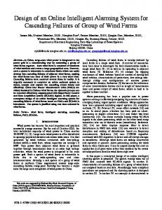
Figure 4. Comparison of system responses between using different controllers corresponding to a step force reference 1
4
4
3 1
4000
Dis ( t ) = A sin (ωt ) + Rnd ( t )
3
2
5
0.2 0.4 0.6 0.8
500
1
1950
1600
(43)
In addition, to evaluate the control stability, a noise signal was added before and after the system plant to generate the perturbation condition for the simulations. The noise source is a combination of a white noise and a sine wave noise, can be expressed as
Kd x10
2000
1500
0
3 Reference Force
III.
200
1.5 P,I,D gains of OTMGFPID
(41)
Reference Force
§ b · b eˆ(ND0) ( n + 1) = ¨ e(ND1) (1) − ND ¸ e − aND ( n ) + ND aND ¹ aND ©
Perturbations
-50
2
1 3
2
4
2
3000 2 2000 4
3
(44)
1 1000
where A and ω are amplitude and frequency parameters; Rnd(t) is the white noise signal. Next, the designed controller was compared with other three advanced control methods by the mean of simulations. The three controllers are a fuzzy PID controller (FPID), a fuzzy PID controller based on an online tuning Grey predictor (OTGFPID-1), and an online tuning fuzzy PID controller based on an online tuning Grey predictor (OTGFPID-2) [6, 8]. Here, the proposed OTMGFPID controller and the compared controllers were applied in turn to the system plant for the simulated force control performances, consequently, performing the comparisons in simulation results. The simulation diagram of the press machine using different controllers is displayed in Fig. 3.
yr y
Figure 3. Diagram of a system using different controllers
0. 0
0
Reference Force 1. 3. OTGFPID2 4. 2
4
FPID 2. OTGFPID1 OTMGFPID
Time [s]
6
8
10
Figure 5. Comparison of system responses between using different controllers corresponding to a multi-step force reference
These compared controllers were constructed from the proposed controller in which the fuzzy PID and the OTGFPID1 have the same fuzzy PID design as that of the OTMGFPID except including the smart learning mechanism. Meanwhile, the OTGFPID-1 and OTGFPID-2 use a same Grey predictor – online tuning Grey predictor of which the step size is selfadjustable as the FPSS of the OTMGGPID controller. In addition, the OTGFPID-2 is based on the online tuning fuzzy PID controller of which the fuzzy PID inference is tuned by a proposed learning mechanism [6]. Finally, the control systems using the four different controllers were built in parallel in the MATLAB/Simulink environment with a 0.001s of sampling rate. B. Simulation Results Simulations have been carried out for checking the performances of the nonlinear system (37) using different controllers in the same working condition including both the noises and disturbances.
485
Simulations with different step force references were performed and the corresponding results are displayed as in figures 4 and 5. As seen in these figures, the controllers were tested in the environment including perturbations of which the amplitude was within 10% and 20% of the desired performance levels. As the result, the perturbation effect on the system response was remarkable. By using the FPID controller, this effect could be reduced (see line 1 – dot-pink lines). However, the FPID without the self-learning ability and Grey predictor, the system responses during the settling time was not stable for all cases. Meanwhile, the controllers with using online tuning Grey predictors always created stable states during the settling time (see lines 2 and 3 – dash-red and dash-dot-dot-blue lines). Nevertheless, the OTGFPID-1 and OTGFPID-2 could not control the system well (the error is about 5% of the desired level) in the disturbed conditions because the perturbations were large and sudden. Only the OTMGFPID controller with both the advanced learning ability and the OTMGP predictor could drive the system to reach the target with the best quality as shown in Fig. 4 and Fig. 5 with the solid-black lines (line 4). These figures shows the ability in estimating noises and disturbance by using the OTMGP predictor as well as the ability in tuning the P, I, and D gains by using the OTFPID controller. The OTFPID tuned automatically their control gains with respect to the control error minimization while the OTMGP produced a compensated control signal corresponding to the estimated perturbation. As the result, the system could rise to the target faster, more stable and could eliminate mostly the effect of noises and disturbances. IV.
CONCLUSIONS
This paper presents a novel control method – online tuning modified-Grey fuzzy PID controller to apply to nonlinear control systems containing large nonlinearities and uncertainties. The OTMGFPID controller was designed as the combination of the online tuning fuzzy PID control part and the online tuning modified-Grey predictor. The OTFPID controller is based on the traditional PID controller combined with the advanced self-tuning fuzzy sets whose structures are smartly optimized online by using the smart learning mechanism to minimize the control error. The PID gains are then updated online based on the fuzzy tuners outputs and through the robust checking conditions, consequently, producing a control signal for the controlled system. The OTMGP with self-tuning ability in the predictor step size takes part in estimating the system output in advance for the OTFPID controller in order to improve the control
quality. In addition, an additive correction to the control signal is produced for each working step by the OTMGP to eliminate the effects of perturbations on the system performance. An investigation on a nonlinear system using the typical controllers and the designed controller were carried out by simulations to evaluate the effectiveness of the proposed control method. The simulation evaluation proved clearly that a nonlinear system using the proposed OTMGFPID controller always enhances a good tracking performance with fast response, high stability and disturbance rejection ability even in case of environment containing large perturbations.
ACKNOWLEDGMENT This work was supported by KETEP, Korea. REFERENCES [1]
J. Wang, D. An, and C. Lou, “Application of fuzzy-PID controller in heating ventilating and air-conditioning system,” Proc. of the IEEE Int. Conf. on Mechatronics and Automation, China, 2006, pp. 2217-2222. [2] K. K. Ahn, D. Q. Truong, and Y. H. Soo, “Self tuning fuzzy PID control for hydraulic load simulator,” Proc. of the IEEE Int. Conf. on Control, Automation and Systems, Korea, 2007, pp. 345-349. [3] M. Guzelkaya, I. Eksin, and E. Yesil, “Self-tuning of PID-type fuzzy logic controller coefficients via relative rate observer,” Engineering Applications of Artificial Intelligence, vol. 16, 2003, pp. 227-236. [4] Y. T. Juang, Y. T. Chang, and C. P. Huang, “Design of fuzzy PID controllers using modified triangular membership functions,” Information Sciences, vol. 178, 2008, pp. 1325-1333. [5] S. Soyguder, and M. Karakose, “Design and simulation of self-tuning PID-type fuzzy adaptive control for an expert HVAC system,” Expert Systems with Applications, vol. 36, no. 3, 2009, pp. 4566-4573. [6] K. K. Ahn, D. Q. Truong, T. Q. Thanh, and B. R. Lee, “Online selftuning fuzzy proportional–integral– derivative control for hydraulic load simulator,” Proc. of IMechE Part I: J. Systems and Control Engineering, vol. 222, no. 2, 2008, pp. 81-95. [7] D. Q. Truong, and K. K. Ahn, “Self Tuning of Quantitative Feedback Theory for Force Control of an Electro-Hydraulic Test Machine,” Control Engineering Practice, vol. 17, no. 11, 2009, pp. 1291-1306. [8] D. Q. Truong, and K. K. Ahn, “Force control for hydraulic load simulator using self-tuning grey predictor – fuzzy PID,” Mechatronics, vol. 19, no. 2, 2009, pp. 233-246. [9] J. L. Deng, “Introduction to Grey System Theory,” J. of Grey System, vol. 1, 1989, pp. 1-24. [10] E. Kayacan, and O. Kaynak, “Grey Prediction Based Control of a NonLinear Liquid Level System Using PID Type Fuzzy Controller,” Proc. of IEEE 3rd Int. Conf. on Mechatronics, 2006, pp. 292-296. [11] Y. Nanhua, M. Wentong, and S. Ming, “Application of adaptive Grey predictor based algorithm to boiler drum level control,” Energy Conversion and Management, vol. 47, no.18-19, 2006, pp. 2999–3007. [12] E. Kayacan, B. Ulutas, and O. Kaynak, “Grey system theory-based models in time series prediction,” Expert Systems with Applications, vol. 37, no. 2, 2010, pp. 1784–1789.
486