coupled amplifier and a monostable multivibrator. The proposed method can be easily integrated into the CMOS design flow. The advantages of the proposed ...
Design of Completion Detection Circuits for Self-timed Systems Operating in Subthreshold Regime Omer Can Akgun, Yusuf Leblebici, Eric A. Vittoz Swiss Federal Institute of Technology (EPFL) Microelectronic Systems Laboratory (LSM) Lausanne, CH-1015, Switzerland E-mail:{omercan.akgun, yusuf.leblebici, eric.vittoz}@epfl.ch
Abstract— In this paper implementation of a novel completion detection method for self-timed, asynchronous subthreshold circuits is presented. By employing the self-timed operation principle, substantial speed gains in the operation of the asynchronous pipelines can be realized. The completion detection system is very simple, consisting of a sensor transistor, a very basic ACcoupled amplifier and a monostable multivibrator. The proposed method can be easily integrated into the CMOS design flow. The advantages of the proposed completion detection system is shown through simulations on an 8-bit ripple carry adder in a standard 0.18µm CMOS process operating at 400mV supply voltage.
I. I NTRODUCTION Power density and power consumption of complex digital systems has become a major concern during the recent years, both due to thermal concerns and due to limited battery lifetime in mobile applications. Any significant reduction in power dissipation can only be achieved by lowering the operating voltage of the circuits. This would be possible by relaxing the constraints of classical strong-inversion operation of MOSFETs, and by accepting the notion that transistors can (and will) be operated well below threshold, in the subthreshold (weak-inversion) regime. In subthreshold mode of operation, the supply voltage can be scaled aggressively and power dissipation can be decreased significantly. There are successful implementations of digital circuits working in the subthreshold region [1]– [3]. Subthreshold operation of static CMOS logic has been analytically analyzed using the EKV model in [4]. According to the analysis, to benefit the most from the subthreshold operation, the logic circuits should be run at their maximum operating frequency with an activity factor α as close to 1 as possible. Maximizing α is non-trivial in synchronous circuits. Because of the fixed time slot for computation, data-dependent processing times cannot be exploited in synchronous operation. Also in a synchronous system, power is consumed with each clock transition regardless of the data or state change. Although clock gating has been proposed as a solution to this problem [5], it cannot provide a comprehensive solution to the problem of data-dependent computation times. On the other hand, asynchronous circuits do not consume clocking
power and have the potential of operating with tunable voltage supplies at an α factor of 1 at the optimum supply voltage. In addition, asynchronous operation also enables the absorption of time-domain (delay) variations that inevitably become more prominent in the subthreshold regime due to the device parameter and temperature variations. Therefore, implementation of efficient asynchronous circuits operating in subthreshold regime would be a subject of high interest. In this work, we demonstrate the design of a novel completion detection system (CDS) for self-timed circuits based on current sensing. The proposed CDS can operate in the subthreshold regime and sense currents in the pA - nA range. The proof of concept is shown by using the proposed system to generate the completion detection signals for an 8-bit ripple carry adder. It has been observed that the improvement in the delay of the overall circuit operation is significant, justifying the use of the CDS. The remainder of the paper is organized as follows. In Section II the basic current equations for MOS transistors operating in the weak inversion regime is given. In Section III the design of the CDS emphasizing the trade-offs in the design of the AC-coupled amplifier is presented. Section IV shows the application and improvements due to the CDS in terms of the delay of the pipeline stage. II. MOS W EAK I NVERSION O PERATION The MOS digital circuits operate in subthreshold regime when the supply voltage is lower than the threshold voltage (VT ) of the transistors. The drain current of an n-channel MOS transistor operating in this regime is given by [4] IDS
VGS − VT = IS exp nUT
�
−VDS 1 − exp UT
�
(1)
where n is a process dependent term called slope factor and is typically in the range of 1.3−1.5 for modern CMOS processes. The value of n depends on the depletion region characteristics of the transistor. VGS and VDS are the gate to source and
Ack
drain to source voltages, respectively. The parameter IS is the specific current which is given by, W (2) L where µ is the mobility of carriers, Cox is the gate oxide capacitance per unit area, UT is the thermal voltage whose value is 26mV at 300K and W L is the aspect ratio of the transistor. Due to the second term in (1), the drain current is 0 when VDS = 0 but reaches its maximum value and saturates with VDS values higher than a few UT . As it is apparent from (1), the drain current of a MOS transistor in subthreshold region shows exponential dependence on the gate-to-source, drain-tosource voltages, slope factor and the operating temperature. To alleviate the problems resulting from the exponential dependence on the supply voltage, process parameters and the operating temperature, self-timed circuits emerge as strong candidates for subthreshold operation. IS = 2nµCox UT2
Acknowledge
Req
Request
C
EN Data
Latch
Req
Worst case delay
C
EN
Purely Combinational Logic
Latch
(a) Fixed delay implementation Ack Acknowledge
Ack
Req
Request
C
EN Data
Latch
Computation Dependent Delay
Req C
Purely Combinational Logic
EN
Latch
(b) Computation based delay implementation Fig. 1.
III. C OMPLETION D ETECTION C IRCUITRY Asynchronous circuits are fundamentally different from their synchronous counterparts. Although the signaling convention is binary, the data propagation through the stages take place by employing handshaking signals, not by using a common clock. A basic 4-phase, bundled data asynchronous pipeline is shown in Fig. 1. In Fig. 1(a) the most common implementation (fixed delay) is shown. In this implementation the Request signal is delayed by an amount equal to the worst case delay of the purely combinational logic stage. This implementation is a similar approach to the synchronous operation, where unnecessary delay, which is fixed regardless of the logic computation time, is introduced. Another version of the 4-phase bundled data pipeline is shown in Fig. 1(b), where the delay should mimic the computation completion time of the logic block as much as possible. In the literature there are examples of completion detection using current sensing methods [7], [8]. The techniques in the mentioned papers use either bipolar transistors, which are not available in standard CMOS processes, or high valued resistors. Although these techniques can be used for detecting current values in the µA - mA range, they cannot be used for detecting the currents for subthreshold operation which are in the pA - nA range because of the high β requirements of the bipolar transistors and difficulty in implementing very high value resistors. The proposed completion detection system consists of a single low threshold voltage (VT ) MOS transistor, an ACcoupled amplifier and a monostable multivibrator (Fig. 2). The current signal is sensed by the diode connected low VT PMOS transistor, converted to a voltage signal and compressed in the log domain. The conceptual sensed waveform that corresponds to the combinational block processing a new input set is shown in Fig. 3. Two operation regions can be discerned in the figure. One is the time when the actual computation is taking place and the other is the settling of the supply node of the
Ack
4-phase bundled data pipeline (After [6]).
VDD AC Amp & Level shift
Combinational Logic
Fig. 2.
Req
Monostable Multivibrator
Block diagram of the proposed completion detection system.
combinational logic block. The settling time depends on the capacitance of the supply node of the logic block and the resistance of the diode connected PMOS transistor. In order to avoid excessive computation delay when compared to the standard implementation, the resistance of the diode connected transistor should be kept as small as possible. After sensing the current signal and converting to a logcompressed voltage signal, amplification of this signal is necessary before feeding it into the monostable multivibrator. The basic AC-coupled amplifier used for amplification is shown in Fig. 4. Diode connected transistors mp1 and mn1 bias the transistors mp2 and mn2, which are acting as an Sensed V signal
Computation Settling
t
Fig. 3. Computation signature detected as the temporary drop of the supply voltage at the drain node of the current sensor device.
30
VDD
mp2
Cload
-A
In
Out
−10
Increasing coupling capacitance
Cload
Ccouple
−40
Cin
Rout
Gain (dB)
Ccouple
0
mn2
−30
mn1
−20
Ccouple
10
Out
n1
Rin
20
mp1 In
−50
20f 70f 120f 170f 220f 270f
−60
Fig. 4. Schematic and the small signal model of the AC-coupled amplifier used to amplify the detected signal.
100
1k
10k
100k
1M
10M
100M
Frequency(Hz)
amplifier, at the maximum gain point for a given size and DC level. In the small signal model the Cin is the total capacitance at the node n1, Rin is the resistance at the same node, −A is the gain of the inverter, Rout is the output resistance of the inverter and Cload is the total capacitance consisting of the parasitic capacitance of the output inverter (amplifier) and the load capacitance.
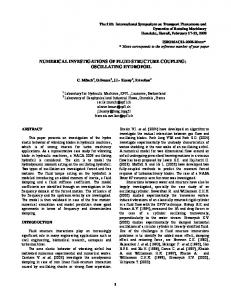
Fig. 5. Frequency domain response of the AC-coupled amplifier for multiple coupling capacitor values. TABLE I M AXIMUM G AIN ( D B) AND BANDWIDTH DATA FOR D IFFERENT VALUES OF Ccouple AND Cload
sCcouple Rin −A Vout (s) = · (3) Vin (s) 1 + sRin (Cin + Ccouple ) 1 + sCload Rout {z } | {z } | LP Response HP Response
The transfer function of the amplifier is given by (3). As it can be seen from the transfer function, the AC-coupled amplifier shows a band-pass response. The high-pass characteristic is due to the coupling capacitor and the input stage, and the low-pass response with gain is the characteristic of the output stage. The important parameters while designing the amplifier and optimizing the whole CDS are the coupling capacitance, parasitic capacitance at node n1, the load capacitance and the gain of the amplifier. By changing the coupling capacitance the first pole location and the amplitude of the signal at the input of the output amplifier can be modified. The frequency domain response of the amplifier for multiple Ccouple values is shown in Fig. 5. The main constraint limiting the coupling capacitance selection value is the available chip area. The load capacitance, affecting the low-pass response of the amplifier is as important as the coupling capacitance and it should be kept as small as possible not to degrade the frequency response of the amplifier. Gain and bandwidth of the AC-coupled amplifier for multiple values of Ccouple and Cload are given in Table I. It can be seen from the data in the table that with increasing load capacitance value, both the maximum gain and the bandwidth of the amplifier degrades, therefore when designing the CDS, the capacitive load of the AC-coupled amplifier should be kept minimum. While designing the system there is a trade-off between the gain of the AC-coupled amplifier and the delay caused by the sensor transistor. If greater delay caused by the sensor transistor (larger spikes in the supply node of the combinational logic
Ccouple (fF)
5 20 70 120 170 220 270
Gain 7.1 16 19.1 20.8 21.9 22.6
BW 568k 228k 163k 136k 120k 111k
Cload (fF) 10 Gain BW 3.07 528k 12.7 196k 16.2 133k 18.3 106k 19.6 91k 20.6 81.6k
15 Gain 0.321 10.3 14.1 16.3 17.9 19
BW 511k 183k 120k 93.7k 78.9k 69.6k
block) can be tolerated, the gain, thus the power consumption of the AC-coupled amplifier can be reduced. The monostable multivibrator [9] is used for converting the sensed signal to a pulse, whose width is proportional to the time spent during computation (shown in Fig. 6). In this monostable multivibrator implementation, a PMOS transistor acts as a variable resistor, whose resistance is modulated by the amplified current signal. By modulating the instantaneous resistance of the PMOS transistor, the RC time constant of the multivibrator is modulated as well, resulting in a pulse whose width is proportional to the area under the current curve of the combinational block. The pulse width of the multivibrator is given by equation (4) � � VDD R (4) T = C(R + Ron ) ln R + Ron VDD − Vth where R is the average resistance of the PMOS transistor during pulse generation, Ron is the resistance of the NOR gate and Vth is switching threshold of the inverter. Assuming Ron