Design of Efficiently-Encodable Rate-Compatible Irregular LDPC Codes Jaehong Kim†, Aditya Ramamoorthy‡, and Steven W. McLaughlin† †School of Electrical and Computer Engineering, Georgia Institute of Technology, Atlanta, GA, U.S.A. E-mail: {onil, swm}@ece.gatech.edu ‡Marvell Semiconductor Inc., Santa Clara, CA, U.S.A. E-mail:
[email protected] Abstract—We present a new class of irregular low-density parity-check (LDPC) codes for finite block length (up to a few thousand symbols). The proposed codes are efficiently encodable and have a simple rate-compatible puncturing structure. For block lengths on the order of n=1000 bits, the codes show good puncturing performance over a wide range of rates. The codes outperform optimized irregular LDPC codes and (extended) irregular repeat-accumulate codes for all rates 0.5~0.9, and are particularly good at high puncturing rates where good puncturing performance has been previously difficult to achieve.
I. INTRODUCTION Low-density parity-check (LDPC) codes are considered good candidates for next-generation forward error control in high throughput wireless and recording applications. Their excellent performance and parallelizable decoder make them appropriate for technologies such as DVB-S2, IEEE 802.16e [1], and IEEE 802.11n [2], [3]. While semiconductor technology has progressed to an extent where the implementation of LDPC codes has become possible, many issues still remain. First and foremost, there is a continual need to reduce complexity (and cost) without sacrificing performance. Second, for applications such as wireless LAN, the system throughput depends upon the channel conditions and hence the code needs to have the ability to operate at different rates. Third, while the LDPC decoder can operate in linear time, it may be hard to perform low-complexity encoding of these codes, e.g. at short block lengths it may be hard to design efficient encoders for the random regular/irregular codes introduced in [4]. This problem can be alleviated somewhat at long block lengths (see [5]). The other option is to resort to quasi-cyclic (QC) LDPC or algebraic constructions that can be encoded by shift registers [6]. Irregular Repeat-Accumulate (IRA) codes were introduced by Jin et al. [7]. These codes have a linear-time encoder and their performance is almost as good as irregular LDPC codes. This class of codes was extended by Yang et al. [8], called extended IRA (eIRA), where they demonstrated high-rate codes with very low error-floors. A popular technique for achieving rate-adaptation in a system is through the use of rate-compatible puncturing. For rate-compatible punctured codes (RCPC), the parity bits of the higher-rate code form a subset of the parity bits of the lower-rate codes. Due to this property, a RCPC can be used effectively in incremental redundancy (IR) automatic repeat request (ARQ) systems. In a system using RCPC the
number of parity bits that the transmitter sends depends upon the rate requirement. At the decoder end, parity bits that are not transmitted are treated as erasures. Thus puncturing provides a low-complexity solution to the rate-adaptation problem since the same encoder and decoder can be used at different rates [9]. In this work, we first show that the performance of eIRA codes can degrade significantly at high-puncturing rates. To alleviate this problem we introduce a new class of LDPC codes that have a linear-time encoder and have good performance under puncturing for a wide variety of rates. We call this class of codes Efficiently-Encodable Rate-Compatible (E2RC) codes. In section II, we present the E2RC construction algorithm. The encoder structure for E2RC codes is explained in section III. Section IV compares the puncturing performance of E2RC codes with that of other irregular LDPC codes. Section V outlines the conclusions. II. THE CODE CONSTRUCTION ALGORITHM The eIRA codes of Yang et al. achieve good performance by assigning degree-2 nodes to nonsystematic bits and ensuring that the degree-2 nodes do not form a cycle amongst themselves. Furthermore, they avoid cycles of length-4 and make the systematic bits correspond to variable nodes of degree higher than two. They ensure efficient encoding by forming the parity in the bi-diagonal structure illustrated on the Fig. 1.
T
1 1 1 1 1 = O 1 1 1 1
Figure 1. Bi-diagonal structure in IRA codes.
It is interesting to see whether there exist other ways of placing the degree-2 nodes so that the above conditions are satisfied. We present below an example of such a placement in Fig. 2. Observe that the column degree of each node is 2 except the last column and that there does not exist any cycle in this matrix. We shall see later that this construction can be generalized and the
1131 1-4244-0355-3/06/$20.00 (c) 2006 IEEE This full text paper was peer reviewed at the direction of IEEE Communications Society subject matter experts for publication in the IEEE ICC 2006 proceedings.
resulting matrices can be used to construct LDPC codes that can be efficiently encoded and have good puncturing performance across a wide range of rates.
1 1 0 0 P = 0 0 0 0
0 0 0 0 0 0 0 0 0 0 1 0 0 0 1 0 0 0 0 0 0 1 0 0 1 0 1 0 0 1 0 0 0 0 0 0 1 0 0 1 0 0 0 0 1 0 0 0 0 0 0 1 0 1 1 1
Figure 2. Another cycle-free structure with weight-2 nodes.
A. Rate-Compatible Puncturing Algorithm Rate compatible puncturing of LDPC codes based on the degree distributions was introduced by Ha et al. [10]. However, this method assumes infinitely long block lengths and extending this to short block lengths is a significant challenge. For the finite length (several thousand symbols) LDPC codes, Ha et al. also proposed efficient puncturing algorithm to have a rate-compatible code [11], [12]. Since our code construction technique is inspired by it, we present a brief description of the algorithm below. 3-SR nodes
1-SR nodes
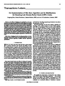
that the k-SR node will be recovered after exactly k iterations of iterative decoding assuming that the channel does not cause any errors. So a higher number of low-SR nodes will reduce the overall number of iterations, which results in good puncturing performance. The general idea is to puncture the lower-SR nodes first. By doing so, punctured nodes can be recovered with the help of other unpunctured nodes in lesser number of iterations. The puncturing algorithm is focused on the selection of the nodes to be punctured by maximizing the number of lower-SR nodes for a given parity-check matrix. The puncturing algorithm presented above works for any given mother code. An important open problem here is the design of good codes for puncturing, i.e., how to design a code to maximize the lower-SR nodes. This is the focus of this paper. B. Algorithm for E2RC Code Construction In this work, we are interesting in designing codes that have a large number of lower-SR nodes. Before describing our design algorithm, we define a k-SR matrix. Definition: The submatrix P of a matrix H is called a k-SR matrix if the columns of P consist of all the k-SR nodes in the matrix H . In our construction the non-systematic part of the mother code parity-check matrix consists of k-SR matrices that can be punctured efficiently. Proposed Algorithm STEP 1 [Parameter Setting] For a given design parameter, M (number of parity bits), the required depth d = log 2 M . Set the size of k-SR matrix as M × (M / 2k), where 1 ≤ k ≤ d . Also, set the size of (d+1)-SR matrix as M ×1 . STEP 2 [Generating k-SR matrix] Generating k-SR matrix of M × (M / 2k). The j-th column of k-SR matrix has the following sequence: k k −1 k −1 hk , j = D 2 ⋅ j D 2 −1 1 + D 2 ,
2-SR nodes
(
)
where 1 ≤ k ≤ d , 0 ≤ j ≤
1-SR nodes
M −1 2k
hk = D M −1 , where k = d + 1
: punctured variable nodes
In the sequence, Di represents the position of nonzero element in a column, i.e., i-th element of the column is nonzero, where 0 ≤ i ≤ M −1 .
: unpunctured variable nodes : check nodes
Figure 3. k-SR node in a graph.
The puncturing algorithm in [11], [12] is based on the following two definitions. A punctured variable node p is called 1-step recoverable (1-SR) node if it has at least one neighboring check node (called survived check node) whose neighboring variable nodes are all unpunctured except for p. Generalizing this, a punctured variable node p is called k-step recoverable (k-SR) node (see Fig. 3) if it has at least one survived check node that is connected to at least one (k-1)-SR node. Furthermore the other nodes that it is connected to need to be m-SR nodes, where 0 ≤ m ≤ k − 1 . Under these conditions, note
STEP 3 [Constructing matrix H2] Construct H2 matrix as follows: H 2 = [1-SR matrix | L | d -SR matrix | (d + 1)-SR matrix ].
STEP 4 [Constructing matrix H1] Find an optimal degree distribution for the whole code (while fixing the number of degree-2 nodes to m − 1 and the number of degree-1 nodes to 1). Construct matrix H1 to satisfy the degree distribution. STEP 5 [Constructing matrix H] Assign H1 as systematic parts and H 2 as nonsystematic parts:
1132 This full text paper was peer reviewed at the direction of IEEE Communications Society subject matter experts for publication in the IEEE ICC 2006 proceedings.
H
[ H1
=
| H2 ] .
2l jl + 2l − 1 = 2k jk + 2k −1 − 1, where 0 ≤ jl ≤
For a desired code rate, we first need to find the optimal degree distribution using density evolution [4]. Note that the degree distribution of the non-systematic part is already fixed by the construction algorithm (see Observation 1 and Corollary 1). For the design convenience, we only consider M = 2d case in the algorithm. However, we can apply this algorithm to any M. In the proposed algorithm, we assign all the degree-2 variable nodes to nonsystematic bits. In Lemma 3, we show that there are no cycles among the degree-2 nodes. Observation 1: Every column in k-SR matrix has weight two except the (d+1)-SR matrix which has weight one. Lemma 1: In the matrix H 2 , any column in k-SR matrix is connected to at least one row of weight-k. Furthermore, this row has exactly one connection to a column from each l-SR matrix, where 1 ≤ l ≤ k − 1 . Proof: Suppose we pick jk th column in k-SR matrix, then the sequence is k ( k −1) ( k −1) hk , jk = D 2 ⋅ jk D 2 −1 1 + D 2
(
= D2
k
⋅ jk + 2( k −1) −1
+ D2
)
k
⋅ jk + 2( k −1) −1+ 2( k −1)
M − 1. 2k Any column (say jl th column) in l-SR matrix has the following sequence: l ( l −1) l l M hl , jl = D 2 jl + 2 −1 + D 2 jl + 2 −1 , where 0 ≤ jl ≤ l − 1 . 2 For the jk th column in k-SR matrix to be connected to a column in l-SR matrix, we can consider the following 4 cases. (Case 1: the first term of hl , jl = the first term of hk , jk ) = D2
k
jk + 2( k −1) −1
+ D2
k
jk + 2k −1
, where 0 ≤ jk ≤
2l jl + 2l −1 − 1 = 2k jk + 2k −1 − 1, where 0 ≤ jl ≤
M −1. 2l
jl = 2k − l −1 (2 jk + 1) − 1 . M − 1 , k − l ≥ 1 , and jl is linear in jk , we can 2k always find a unique jl for jk such that
Since 0 ≤ jk ≤
(Case 4: the second term of hl , jl
2l jl + 2l − 1 = 2k jk + 2k − 1, where 0 ≤ jl ≤
M −1 . 2l
Then, by some manipulations jl should be jl = 2k − l ( jk + 1) − 1 . M − 1 , k − l ≥ 1 , and jl is linear to jk , we can 2k always find a unique jl for jk such that
Since 0 ≤ jk ≤
M −1 . 2l Thus, we can always find only one connection in each l-SR matrix for each element in k-SR matrix. Now, we now need to show that one row is of weight-k. Suppose k + 1 ≤ m ≤ d and there exists a column ( jm th column) in m-SR matrix: 1 ≤ 2k − l − 1 ≤ jl = 2k −l ( jk + 1) − 1 ≤
M −1 . 2m We will show that we cannot find jm for a given jk considering the following 2 cases. (Case 1: the first term of hk , jk = the first term of hm, jm ) hm , jm = D 2
m
jm − 2( m−1) −1
+ D2
m
jm −1
, where 0 ≤ jm ≤
jk = 2m − k −1 ( 2 jm + 1) − 1/ 2 , 1442443 { fraction
jk = 2m − k ( jm + 1) − 1/ 2 , 14243 {
fraction
Since k − l ≥ 1 , this means that the first term on the RHS of the expression above is an integer and thus the RHS is a fraction. But this is impossible since jl is an integer. (Case 2: the first term of hl , jl = the second term of hk , jk ) 2l jl + 2l −1 − 1 = 2k jk + 2k − 1, where 0 ≤ jl ≤
M − 2k − l −1 − 1. 2l = the second term of hk , jk )
0 ≤ 2k − l −1 − 1 ≤ jl = 2k − l −1 (2 jk + 1) − 1 ≤
which is impossible since m − k ≥ 1 and jk is an integer. (Case 2: the first term of hk , jk = the second term of hm, jm )
jl = 2k − l −1 ( 2 jk + 1) − 1/ 2 , 144244 3 {
M −1. 2l
Then, by some manipulations jl should be jl = 2k − l ( jk + 1) − 1/ 2 , 14243 { integer
Then, by some manipulations jl should be
integer
Then, by some manipulations jl should be integer
M −1 . 2l
fraction
integer
fraction
which is impossible since m − k ≥ 1 and jk is an integer. Thus, the first term of hk , jk does not have any common positions with any columns in the m–SR matrix, which means that the first term does not have any connections on the right and is connected to k columns on the left. Thus, it participates in a weight-k row. ■ Corollary 1: The right degree distribution (edge perspective) of matrix H 2 is as follows: d +1
ρ ( x) = ∑ ρi xi −1 ,
which is impossible since k − l ≥ 1 and jl is an integer. (Case 3: the second term of hl , jl = the first term of hk , jk )
i =1
1133 This full text paper was peer reviewed at the direction of IEEE Communications Society subject matter experts for publication in the IEEE ICC 2006 proceedings.
where ρi =
and ρ d +1
i
for 1 ≤ i ≤ d ,
d j d +1 2i ⋅ ∑ j + d 2 j =2 2 d +1 = . d j d +1 d 2 ⋅ ∑ j + d 2 j =2 2
Proof: First, consider k-SR matrix when 1 ≤ k ≤ d . From the Lemma 1, if we pick a column in the k-SR matrix, the first element of the column is included in the row of weight k , and the second element of the column has the row weight greater than or equal to k . To be precise, the second element of the column has row weight k only if k = d . The number of columns in the k-SR matrix is M / 2k and each column is connected to one weight-k row. Thus, the number of rows having weight k is M / 2k . For a (d+1)-SR matrix, there is only one weight (d+1) row, which is connected to the second element of the column in the d-SR matrix. Summing the number of rows having weight-k results in M M M 1 + + L + d + 1 = M 1 − d + 1 = M . 21 22 2 2 ■ From the Observation 1 and Corollary 1, we can determine the exact degree distributions for the nonsystematic parts, namely the H 2 matrix. For a desired code rate, we can find optimal degree distributions for the whole code while fixing these degree distributions for H 2 . Then we can get the degree distributions for the H1 matrix. For the systematic part, namely the H1 matrix, we choose variable nodes of higher degree greater than two. Since all of the nodes except one node are degree 2 in H 2 , the fraction of degree-2 nodes in degree distributions is very high. For a finite length code, the higher portion of degree-2 nodes cause better threshold performance, but a big fraction of degree-2 nodes can result in a small minimum distance, causing a greater probability of decoding errors and higher error floors. To reduce these effects, we use methods such as those presented in [13-16] when we construct the H1 matrix. In Lemma 2 and 3, we will show that the proposed matrix does not have any cycles that consist of only degree-2 nodes. Lemma 2: Suppose there exists a length-2s cycle in a matrix which consists of only weight two columns. Consider the submatrix formed by the subset of columns that participates in the cycle. Then, all the participating rows in the cycle must have degree two in that submatrix. Proof: To have a length-2s cycle, the number of columns participating in the cycle needs to be s and the number of rows participating in the cycle needs to be s. Let us denote the submatrix formed by the columns participating in the cycle by U. Then, the number of edges in U is 2s since each of the
columns has degree two. Each row participating in the cycle must have a degree greater than or equal to two in U since each row has to link at least two different columns in U . Suppose there is a row having degree strictly greater than two in U . Then, there should be a row having a degree less than two in U i.e. equal to one, since the average row weight in U is two (the number of edges / the number of rows = 2s / s = 2), which is a contradiction. This is because a row that has degree-one in U cannot participate in a cycle with the columns in U . Thus, every participating row must have degree two in U . ■ Armed with Lemma 2, we will prove that the proposed matrix H 2 is cycle free. Lemma 3: The matrix H 2 is cycle free. Proof: Suppose that there exist s columns v1 , v2 ,..., vs that form a cycle of length 2s . We form the M × s submatrix formed by the columns. Let us denote this submatrix H s . Suppose that column vi belongs to the ki -SR matrix in H 2 . Find the minimum value of ki . Let us call it kmin . Applying Lemma 1, we have that vkmin has exactly one connection to each l-SR matrix, where 1 ≤ l < k min , and no connection to m-SR matrices where m > kmin , i.e., there is a check node connected to vkmin that is singly-connected in the submatrix H s . Applying Lemma 2, we realize that a cycle cannot exist amongst the s columns. ■ For the proposed codes, rate-compatibility can be easily obtained by puncturing nodes from left to right in H 2 matrix. Equivalently, we puncture the nodes in the lower-SR matrix first for a desired code rate. The proposed codes not only have simple rate-compatible puncturing but also an efficient encoding structure. We describe the encoding structure in the following section. III. ENCODER STRUCTURE For the parity-check matrix H of an LDPC code obtained from the proposed algorithm, the systematic generator matrix G is given by G = [ I k | P ] , H = [ H1 | H 2 ] . Since H T G ⋅ H T = [ I k | P ] ⋅ 1T = H1T + P ⋅ H 2T = 0 , H 2
we can get P = H1T ⋅ H 2−T . Then the systematic codeword is represented by c = m ⋅ G = m ⋅ [ I k | P ] = m | m ⋅ H1T ⋅ H 2−T . Let hk , j be the j-th column in k-SR matrix in H 2
(
)
D 2k −1 −1 1 + D 2k −1 , where j = 0, 1, L , M − 1 . 2k The following Lemma 4 gives us the sequence of the column in H 2−T , which enables simple encoding structure.
hk , j = D 2
k
⋅j
1134 This full text paper was peer reviewed at the direction of IEEE Communications Society subject matter experts for publication in the IEEE ICC 2006 proceedings.
Lemma 4: Let hk , j = D 2 g m ,n =
k
⋅j
2m−1 −1
∑ i =0
(
However, the actual degree distributions are slightly different to compensate the right degree of H 2 .
)
D 2k −1 −1 1 + D 2k −1 , where j = 0, 1, L, M − 1 , 2k
D
2m n + i
, where n = 0, 1, L ,
M 2
m
λ ( x ) = 0.00030 + 0.30210 x + 0.27136 x + 0.42625 x 2
−1.
5
8
if k = m, and j = n
gm, n for each case of k, m and j, n.
■ In fact, gm, n is the sequence of H 2−T corresponding to hk , j of H 2 in Lemma 4. Since we have column sequences for both H1T and H 2−T , we can implement a simple encoder as shown in Fig. 4 (a similar observation was made in [8]). This encoder can be implemented simply with shift-registers, switches, and exclusive-OR operators. Due to lack of space, we omit the details. Another way to implement the encoder of the proposed E2RC codes is by using a simple erasure decoder. Recall that all the nodes in k-SR matrix can be recovered in k iterations with erasure decoder since they are all k-SR nodes. For the proposed codes, even if all the parity bits are erased, we can recover the exact parity bits within (d+1) iterations using a simple erasure decoder or general LDPC decoder of message-passing algorithm. RA, IRA and eIRA codes can also be encoded by using the erasure decoder. However for these codes the number of iterations of erasure decoding required is higher. In the transceiver system, this can be a great advantage in terms of complexity. We only need to provide an LDPC decoder for both encoding and decoding, and do not need any extra encoder.
m C=[m|p] H2-T
p
Figure 4. An example of encoding structure of the proposed E2RC codes.
IV. SIMULATION RESULTS We consider rate-1/2 codes with code length of 1024 for the E2RC codes. When we generate the E2RC codes, we try to keep the same optimal degree distributions for the codes as those in [8] for rate-1/2 codes, which are used to generate general irregular LDPC codes and eIRA codes in the following simulations:
λ ( x ) = 0.30780 x + 0.27287 x 2 + 0.41933 x 6 5
6
ρ ( x ) = 0.4 x + 0.6 x .
10
11
+ 0.00354 x .
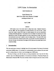
First, we compare the performance between the proposed E2RC codes and the eIRA codes. We design eIRA codes of length 1026. We apply the algorithm proposed in [15], [16] to design the systematic part of both E2RC codes and eIRA codes for having the better girth characteristics. As shown in Fig. 5, the mother code performance of two codes shows almost the same. However, E2RC codes outperform eIRA codes at every puncturing rate. In this simulation, we adopt the random puncturing strategy for puncturing eIRA codes. 10-1 E2RC codes (K=512) eIRA codes (K=513) 10-2
10-3
BER
otherwise.
H1T
9
0.01064 x + 0.00592 x + 0.00325 x
Proof: Due to lack of space, we omit the details of the proof. We can easily check the intersections of the sequences hk , j and
m
7
ρ ( x ) = 0.41147 x + 0.54626 x + 0.01892 x +
Then, 1, hk , j ⋅ gm ,n = 0,
6
6
10-4
10-5
10-6 1
2
3
4
5
6
7
Eb /No [dB]
Figure 5. Puncturing performance comparison between the proposed E2 RC codes (filled circle) of length=1024 and the eIRA codes (unfilled circle) of length=1026 with random puncturing. Curves are for rate=0.5, 0.6, 0.7, 0.8 and 0.9 from left to right.
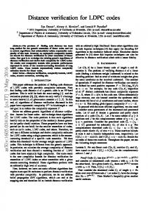
Next, we adopt the intentional puncturing algorithm in [11], [12] to the eIRA codes, but in this case we face puncturing limitations. In fact, the puncturing algorithm in [11], [12] assigns 256 nodes as 1-SR nodes, and cannot find further k-SR nodes (k ≥ 2) if we try to maximize the number of 1-SR nodes. To get a high rate (R = 0.7, 0.8, 0.9) in eIRA codes, we puncture randomly after the puncturing limitation (256 1-SR nodes), which destroys the structure of 1-SR nodes resulting in poor performance. As shown in Fig. 6, the puncturing performance of the E2RC codes is better than that of eIRA codes as the code rates are increased even though we apply the best-effort intentional puncturing algorithm. For a code rate of 0.9, the E2RC codes show a 1.1dB coding gain over eIRA codes at a BER of 10-5. To compare the puncturing performance with general irregular LDPC codes, we generate an irregular LDPC codes having the same degree distributions as in [8]. The code length of this code is 1026, and we also apply the algorithm in [15], [16] algorithm to generate the code. From the rate-1/2 mother
1135 This full text paper was peer reviewed at the direction of IEEE Communications Society subject matter experts for publication in the IEEE ICC 2006 proceedings.
codes, we generate punctured codes of rate 0.6, 0.7, 0.8, and 0.9 using the puncturing algorithm in [11], [12]. In Fig. 7, the proposed E2RC codes show better performance in all ranges of rates. For the rate 0.7 case, the puncturing of the proposed codes is 0.2dB better than the general irregular LDPC codes at a BER of 10-5 and for the rate of 0.9 the gain increases to 1.2 dB. 10-1 2
E RC codes (K = 512) eIRA codes (K = 513)
characteristics. From simulations the performance of the E2RC codes (mother codes) is as good as that of eIRA codes and other irregular LDPC codes. Finally, the E2RC codes show better puncturing performance than other irregular LDPC codes and eIRA codes in all ranges of code rates. From simulations, the punctured E2RC codes of rate 0.9 outperform the best effort puncturing of the irregular LDPC codes at a BER of 10-5 by 1.2 dB. Compared to eIRA codes of rate 0.9, E2RC codes show 1.1dB gain at a BER of 10-5.
10-2
REFERENCES
10-4
[1] [2] [3] [4]
10-5
[5]
BER
10-3
[6]
10-6 2
4
6
8
Eb/No [dB]
Figure 6. Puncturing performance comparison between the proposed E2 RC codes (filled circle) of length=1024 and the eIRA codes (unfilled circle) of length=1026 with intentional puncturing. Curves are for rate=0.5, 0.6, 0.7, 0.8 and 0.9 from left to right.
[7] [8] [9]
10-1 2
E RC codes (K = 512) Irregular LDPC codes (K = 513)
[10]
10-3
[11]
10-4
[12]
10-5
[13]
BER
10-2
10-6 1
2
3
4
5
6
[14]
7
Eb/No [dB]
Figure 7. Puncturing performance comparison between the proposed E2 RC codes (filled circle) of length=1024 and the irregular LDPC codes (unfilled circle) of length=1026 with intentional puncturing. Curves are for rate=0.5, 0.6, 0.7, 0.8, and 0.9 from left to right.
[15] [16]
IEEE P802.16e/D6, February 2005. 11-04-0889-03-000n-tgnsync-proposal-technical-specification.doc. 11-04-0886-06-000n-wwise-proposal-ht-spec.doc. T. Richardson, A. Shokrollahi, and R. Urbanke, “Design of capacityapproaching irregular low-density parity-check codes,” IEEE Trans. Inform. Theory, vol. 47, pp. 619-637, Feb. 2001. T. Richardson and R. Urbanke, “Efficient Encoding of Low-Density Parity-Check Codes,” IEEE Trans. Inform. Theory, vol. 47, no. 2, pp. 638-656, Feb. 2001. S. Lin, L. Chen, J. Xu and I. Djurdjevic, “Near Shannon limit quasicyclic low-density parity-check codes,” in Proc. 2003 IEEE GLOBECOM Conf. San Francisco, CA, Dec. 2003. H. Jin, A. Khandekar, and R. McEliece, “Irregular repeat-accumulate codes,” in Proc. 2nd. Int. Symp. Turbo Codes and Related Topics, Brest, France, pp. 1-8, Sept. 2000. M. Yang, W. E. Ryan, and Y. Li, “Design of Efficiently Encodable Moderate-Length High-Rate Irregular LDPC Codes,” IEEE Trans. Comm., vol. 52, no. 4, pp. 564-571, Apr. 2004. J. Hagenauer, “Rate-compatible punctured convolutional codes (RCPC codes) and their applications,” IEEE Trans. Comm., vol. 36, pp. 389-400, Apr. 1998. J. Ha, J. Kim, S. W. McLaughlin, “Rate-Compatible Puncturing of Low-Density Parity-Check Codes”, IEEE Trans. Inform Theory, vol.50, no. 11, Nov. 2004. J. Ha, J. Kim, D. Klinc, and S. W. McLaughlin, "Rate-Compatible Punctured Low-Density Parity-Check Codes with Short Block Lengths", accepted to IEEE Trans. Inform. Theory, 2005. J. Ha, J. Kim, and S. W. McLaughlin, “Puncturing for Finite Length Low-Density Parity-Check Codes,” in Proc. Int. Symp. Inform. Theory, Chicago, 2004. X. Hu, E. Eleftheriou, and D. M. Arnold, “Progressive edge-growth Tanner graphs,” in Proc. IEEE GLOBECOM, San Antonio, Texas, Nov. 2001, pp. 995-1001. T. Tian, C. Jones, J. D. Villasenor, and R. D. Wesel, “Selective Avoidance of Cycles in Irregular LDPC Code Construction,” IEEE Trans. On Comm., vol. 52, no. 8, pp. 1242-1247, 2004 A. Ramamoorthy and R. D. Wesel, “Construction of Short Block Length Irregular Low-Density Parity-Check Codes,” in Proc. IEEE Int. Conf. on Comm., Paris, June 2004. W. Weng, A. Ramamoorthy, and R. D. Wesel, “Lowering the Error Floors of High-Rate LDPC Codes by Graph Conditioning,” VTC 2004, Los Angeles, California.
V. CONCLUSION We have proposed a class of codes, E2RC codes that have several strong points. First, they are efficiently encodable. We have derived the sequences for the encoder, which enables low-complexity encoder implementation. We also showed that a simple erasure decoder can be used for the linear-time encoding of these codes. Thus, we can share a message-passing decoder for both encoding and decoding if it is applied to the transceiver systems which require an encoder/decoder pair. Second, we have shown that the nonsystematic parts of the parity-check matrix are cycle-free, which ensures good code
ACKNOWLEDGEMENT This work is supported by Samsung Advanced Institute of Technology. Dr. Ramamoorthy was supported by the state of California, Conexant, and Texas Instruments through UC Discovery Grants COM-04-100 and COM-04-10155.
1136 This full text paper was peer reviewed at the direction of IEEE Communications Society subject matter experts for publication in the IEEE ICC 2006 proceedings.