Appl. Math. Inf. Sci. 7, No. 5, 2061-2069 (2013)
2061
Applied Mathematics & Information Sciences An International Journal http://dx.doi.org/10.12785/amis/070547
Design of Hexi Cipher for Error Correction — Using Quasi Cyclic Partial Hexi Codes K. Ilanthenral∗ and K. S. Easwarakumar Department of Computer Science and Engineering, Anna University, Chennai 600 025, India Received: 9 Feb. 2013, Revised: 11 Jun. 2013, Accepted: 14 Jun. 2013 Published online: 1 Sep. 2013
Abstract: This paper presents a new cipher called the hexi cipher which makes use of a new class of codes called quasi cyclic partial hexi codes. This hexi cipher is a modification of the Advanced Encryption Standard (AES). It alters the mixed column operation of the AES and makes use of quasi cyclic partial hexi codes for error correction instead of the Maximum Distance Separable (MDS) code that has no error correcting capacity within the AES. The hexi cipher has the capacity to detect 99% of the errors and correct nearly 25% of the errors that occur, thus, it has a better error correcting capacity than existing error correcting ciphers. Keywords: AES; Encryption; Error Detection; Error Correction; Quasi Cyclic Partial Hexi Codes
1 Introduction This paper introduces a new class of codes that are effective in enabling error correction in Advanced Encryption Standard (AES) [5]. The mix column operation of AES uses a Maximum Distance Separable (MDS) code, it has no error detection capacity. Later, researchers have modified the mix column module in AES to produce error correction capacity and thus increased security. In 2007, Mathur had introduced two new ciphers namely high diffusion (HD) cipher and pyramid cipher [3]. He had defined high diffusion codes, which were used in the mix column operation instead of the existing MDS code, to produce HD cipher. Czapski and Nikodem in 2008 had created error detection and error correction procedures for the AES, which detected any byte error and over 99% of word errors [4]. A new approach for the improvement of coding gain in channel coding using AES and Maximum A Posteriori (MAP) algorithm was proposed, by Ayyaz Mahmood in 2008 [1]. In 2009, Nakahara and Abrohao had replaced the shift rows and mix columns operations by a new involutory matrix operation in every round [8] and left an open problem to determine larger involutory MDS matrices, for AES/Rijndael of block length 160, 192 and 224. In the same year, Cam and et al had embedded a turbo encoder block in AES encryption block in the first round after sub bytes block [2]. In 2011, Elumalai and Reddy had used a ∗ Corresponding
8 × 8 MDS matrix instead of the 4 × 4 MDS matrix used in AES [6]. The branch number was raised to 9 from 5 so as to increase the diffusion. The necessity to construct codes that are useful in AES, is due to its lacking in error correcting capacity. Mostly, codes used are not dependent on the hexadecimal system, whereas AES operates on the hexadecimal system. A new class of codes which are based on the hexadecimal data is introduced in this paper to support AES not only in security but also in error detection and correction. Hexi cipher which has better error correcting capacity than existing ciphers like HD cipher and pyramid cipher is introduced in this paper. Hexi cipher corrects nearly 12 bytes of 48 bytes transmitted whereas HD cipher corrects 7 bytes of 36 bytes transmitted and pyramid cipher corrects 4 bytes of 24 bytes transmitted. The rest of the paper is organized as follows. Section two introduces a new class of codes called hexi codes, which are based on the hexadecimal system, Hamming metric is defined on these new class of codes. Section three deals with the error correction of these codes using coset leader method. Hexi polynomial codes and quasi cyclic partial hexi codes are defined in section four. Section five provides the construction of hexi cipher, which is a modification of AES, with error correction capability. Concluding remarks and further directions are given in section six.
author e-mail:
[email protected] c 2013 NSP
Natural Sciences Publishing Cor.
2062
K.Ilanthenral , K. S. Easwarakumar: Design of Hexi Cipher for Error...
2 Hexi Codes This section introduces a new class of codes called hexi codes and their properties. Let S = {0, 1, 2, . . . , F} be the set of symbols of hexadecimal number system. Let the operator ‘⊗’ denote multiplication modulo x4 + x + 1, and ‘⊕’ denote XOR modulo 2. Then, (S, ⊕, ⊗) is a field of order 16 and each element is inverse of itself with respect to ⊕. Let V n = {(x1 , . . . , xn )|xi ∈ S; 1 ≤ i ≤ n} be an n-dimensional vector space defined over S. Definition 1.A block code of length n with (24 )k codewords is called a hexi (n, k) block code, denoted by CH (n, k), if and only if its (24 )k codewords form a k-dimensional subspace of the vector space V n of all the n tuples over the field S modulo x4 + x + 1. The method for generating these CH (n, k) codes using the generator matrix G is as follows. G is given in Equation 1. g00 g10 G= .. .
g01 g11 .. .
gk−1,0 gk−1,1
g02 . . . g0,n−1 g12 . . . g1,n−1 .. .. . . gk−1,2 . . . gk−1,n−1
s0 = r0 + r5 + r6 .F s1 = r1 + r4 .A + r5 .C
(1)
gi, j ∈ S; for 0 ≤ i ≤ k − 1 and 0 ≤ j ≤ n − 1. Consider u = (u0 , u1 , . . . , uk−1 ), the message to be encoded, the corresponding codeword v is given by v = u.G. Every codeword v in CH (n, k) is a linear combination of k codewords. For example, let 0 A1B100 G = 1 C 0 7 0 1 0 F 021001 be the generator matrix of the CH (7, 3) hexi block code. Consider the message u = (A 0 1) to be encoded. The codeword v = uG is given by (F 8 8 3 A 0 1). Since the generator matrix G is in the standard form G = (A; I3×3 ), the parity check matrix can be got in the standard form as H = (I4×4 , AT ), 10000 1F 0 1 0 0 A C 0 . H = 0010 1 0 2 0001B7 1 The generator matrix can be in any other form. The parity check matrix can be found out by the usual methods used for linear codes. The syndrome obtained from the parity check matrix H helps one to detect the error from the received word. The syndrome of the hexi block code, functions in the same manner as in the case of linear block code. The syndromes and error detection described below are recalled from [9]. When r is received, the receiver computes s = r.H T = (s0 , s1 , . . . , sn−k−1 ) which is called the syndrome of r. When s 6= (0), r is not
c 2013 NSP
Natural Sciences Publishing Cor.
a codeword and the presence of errors has been detected. When s = (0), r is a codeword, it need not be the transmitted codeword. In certain cases, when the error pattern e is identical to a non zero codeword, r is the sum of two codewords, which is a codeword, and consequently r.H T = (0). These errors are not detectable. The receiver accepts r as the transmitted codeword. Error patterns of this kind are called undetectable error patterns. In case of hexi codes, the remaining (24 )k − 1 non zero codewords can lead to undetectable errors, so there are (24 )k − 1 undetectable error patterns. The syndrome s depends only on e and not on v. Because r is the vector sum of v and e, it follows from s = r.H T . That is s = r.H T = (v + e)H T = v.H T + e.H T . However v.H T = 0. So s = e.H T . Let r = (r0 , r1 , r2 , r3 , r4 , r5 , r6 ) be the received vector. Then the syndrome will be given by s = (s0 , s1 , s2 , s3 ). The syndrome digits using H are
s2 = r2 + r4 + r6 .2 s3 = r3 + r4 .B + r5 .7 + r6 . Consider the CH (7, 3) hexi code given above for illustration. Suppose r = (5 8 8 3 A 0 1) is the received codeword, r.H T = (A 0 0 0). Since s = r.H T 6= (0), the received codeword has error. s0 = A, so the possible error positions are r0 , r5 and r6 . This CH (7, 4) hexi code has (24 )3 hexi codewords and (24 )3 − 1 undetectable error patterns. The Hamming metric of the hexi code is given. Definition 2.For any 2 vectors x = (x1 , . . . , xn ) and y = (y1 , . . . , yn ) in V n , the Hamming distance d(x, y) and Hamming weight w(x) are defined as follows: d(x, y) =| {xi : xi 6= yi ; xi ∈ x; yi ∈ y} | w(x) =| {xi : xi 6= 0; xi ∈ x} | .
(2)
For instance, let x = (F 8 8 3 A 0 1) and y = (3 D 1 2 1 3 0), w(x) = w(y) = 6 and d(x, y) = 7. Since F2n4 = S is akin to Fqn ; all theorems and definitions in Fqn holds good for F2n4 . These notions are reformulated to suit hexi code CH = CH (n, k). If CH is a hexi code, the sum of two codewords is also a codeword in CH . It follows that d(x, y) = w(x + y), that is the hamming distance between two codewords is equal to the hamming weight of some other codeword. Definition 3.The minimum distance dmin of a hexi code CH is defined as dmin =
min d(x, y). x, y ∈ CH x 6= y
(3)
Appl. Math. Inf. Sci. 7, No. 5, 2061-2069 (2013) / www.naturalspublishing.com/Journals.asp
Table 1: Standard Array for Syndrome decoding Coset Leaders Codewords Syndrome s=0 v1 = 0 v2 . . . v24k e2 H T e2 e2 + v2 . . . e2 + v24k e3 H T e3 e3 + v2 . . . e3 + v24k .. .. .. . . . el H T el el + v2 . . . el + v24k .. .. .. . . . e24(n−k) H T e24(n−k) + v2 e24(n−k) . . . e24(n−k) + v24k
Table 2: Example of Standard Array and Coset Leader Coset leaders Syndrome 0000000 . . . 3D12130 EC26011 0000 1000000 . . . 2D12130 FC26011 1000 2000000 . . . 1D12130 CC26011 2000 0000010 . . . 3D12130 EC26001 1C07 A000000 . . . 9D12130 4C26011 A000 B000000 . . . 8D12130 5C26011 B000 0010100 . . . 3D02030 EC16111 A0B0 C000000 . . . FD12130 2C26011 C000 0000001 . . . 3D12131 EC26010 F021
3 Error Correction The error correction capacity of hexi code is discussed in this section. Theorem 1.The number of errors a hexi code can correct is t = ⌊(dmin − 1)/2⌋, and this code can detect l errors where t + l + 1 ≤ dmin and l > t. Proof.: Proof is similar to that of linear block code. Correction of errors in any code is a complicated process. There are 24k error patterns that result in same syndrome and the true error pattern e is just one of them. Determining the true error vector e is not easy. The coset leader method is used for error correction, by making use of the standard array and syndrome decoding described in [9]. The standard array is given by Table 1. Here ei ’s are coset leaders, 2 ≤ i ≤ 24(n−k) ; v j ’s are non zero codewords, 2 ≤ j ≤ 24k . The corrected codeword v j is obtained by using the syndrome of the received codeword r. The coset leader ei , related to the syndrome, is added to r to obtain the corrected codeword. A part of the table of coset leaders for the above mentioned hexi code is given by Table 2. Only a few codewords are dealt here since this code has 163 codewords, it is not feasible to cover them fully. Let the received codeword be r = (5 8 8 3 A 0 1). The syndrome s = (A 0 0 0) and the related coset leader is (A 0 0 0 0 0 0). The coset leader is added with the received codeword; (5 8 8 3 A 0 1) ⊕ (A 0 0 0 0 0 0) = (F 8 8 3 A 0 1). The corrected codeword is obtained.
2063
4 Hexi Polynomial Codes Hexi polynomial codes are of two types, xn + 1 and xn + t (t ∈ S and t 6= 1). When xn + 1 is used, it forms a usual cyclic code, g(x) is a polynomial which divides (xn + 1) and its coefficients are from S. Since these class of hexi polynomial codes are similar to usual cyclic codes, dual code and other properties can be defined in the usual way for these codes. To generate a CH (n, k) cyclic hexi code, consider only the polynomial of the form xn + 1. Instead of xn + 1, consider xn + t (t ∈ S); t 6= 1, then xn + t = g(x) × h(x), g(x) and h(x) are polynomials belonging to S[x]. Let G be the generator matrix associated with generator polynomial g(x). Let H be the parity check matrix associated with the parity check polynomial h(x). The CH (n, k) code is not cyclic. Clearly GH T = (0). If (x1 . . . xn ) ∈ CH (n, k), then in general (xn x1 . . . xn−1 ) ∈ / CH (n, k). CH (n, k), the hexi polynomial code generated by the polynomial g(x) is defined as follows. Definition 4.Let xn + t ∈ S[x], t ∈ S \{1}, be a hexi polynomial in S[x]. If xn + t = g(x) h(x) where G is the generator matrix associated with the hexi polynomial g(x) and H is the parity check matrix associated with h(x). If g(x) generates a code say CH (n, k), then CH (n, k) is the hexi polynomial code associated with the hexi generator polynomial g(x). For example, consider the generator polynomial g(x) = (x4 + Cx3 + Fx2 + A) and given (x7 + F) = (x4 + Cx3 + Fx2 + A)(x3 + Cx2 + 8). Let the generator matrix G be given by g(x). A0FC 1 00 G = 0 A 0 F C 1 0 , 0 0A 0FC1 G generates a CH (7, 3) hexi polynomial code. The codeword v for the message u = (A 3 F) is given by u. G = (8 D 0 3 7 B F). Let H be the parity check matrix given by the parity check polynomial (x3 + Cx2 + 8), 00 0 1C08 0 0 1 C 0 8 0 . H = 0 1 C 0 8 0 0 1C 0 8 0 00 Let r be the received codeword. The syndrome of r can be calculated by s = r.H T . Let r = (8 D 0 3 7 B F), the received codeword, without any error. Then the syndrome should be all zeros; r.H T = (0 0 0 0). This hexi polynomial code is not cyclic. Since v1 = (8 D 0 3 7 B F) is a codeword then v2 = (F 8 D 0 3 7 B) is also supposed to be a codeword if this polynomial hexi code is cyclic. To prove that v2 is a codeword is to show that v2 . H T = (0) i.e., the syndromes are zero. But v2 . H T = (0 0 0 5). The syndrome is not zero, hence it is not a codeword in CH (7, 3). The definition of quasi cyclic code is recalled from [9].
c 2013 NSP
Natural Sciences Publishing Cor.
2064
K.Ilanthenral , K. S. Easwarakumar: Design of Hexi Cipher for Error...
Table 3: Codewords of (16, 4) quasi cyclic partial hexi code Message Codewords Hexicodes 0 0000 0000 0000 0000 0000 8 1111 0110 1000 0010 F682 4 0010 1111 0110 1000 2F68 2 0110 1000 1111 0110 82F6 1 0110 1000 0010 1111 682F C 1101 1001 1110 1010 D9EA A 0111 0100 0111 0100 7474 9 1001 1110 1010 1101 9EAD 6 1010 1101 1001 1110 AD9E 5 0100 0111 0100 0111 4747 3 1110 1010 1101 1001 EAD9 F 0011 0011 0011 0011 3333 E 0101 1011 0001 1100 5B1C D 1011 0001 1100 0101 B1C5 7 1100 0101 1011 0001 C5B1 B 0001 1100 0101 1011 1C5B
Definition 5. [9] A quasi cyclic code is a linear code for which cyclically shifting a codeword, a fixed number n0 6= 1 (or a multiple of n0 ) of symbol; positions either to the right or to the left results in another codeword. The integer n0 is called the shifting constraint. If the shifting constraint n0 = 1, a quasi cyclic code is a cyclic code. Consider the special case where the shifting constraint n0 is 4. The definition of quasi cyclic partial hexi codes is as follows. Definition 6.A quasi cyclic partial hexi code is a quasi cyclic code, where the shifting constraint n0 = 4 and the symbols are represented in hexadecimal. For example, consider the following quasi cyclic partial hexi code, let the generating matrix G of the code be given in the following 1111 0110 1000 0010 0010 1111 0110 1000 G= . 1000 0010 1111 0110 0110 1000 0010 1111 This generator matrix G can represented using symbols from the field GF(24 ). F 6 8 2 2 F 6 8 . (4) G= 8 2 F 6 6 8 2F The codewords of (16, 4) quasi cyclic partial hexi code generated by G are given in Table 3, are cyclic and they are unique. G−1 is used to get the message back. E 9 A 3 3 E 9 A . (5) G−1 = A 3 E 9 9 A 3E
c 2013 NSP
Natural Sciences Publishing Cor.
Some properties of these quasi cyclic partial hexi codes are given below. Remark.Any quasi cyclic partial hexi code CH will be of the form CH = (n42 , n4) and the number of elements in CH are 24n . Hence the quasi cyclic partial hexi code CH (16,4) generated by the G given in Equation (4) has 16 codewords since n = 1. Remark.A (n42 , n4) quasi cyclic partial hexi code will be generated, only if the generator matrix is such that the 4n rows are linearly independent, so that the codewords are unique. Proposition 1.If any quasi cyclic partial hexi code C be generated by a matrix G having G−1 as its inverse, then G−1 may not in general generate a quasi cyclic partial hexi code. Proof.The G−1 given in (5) above does not generate a quasi cyclic partial hexi code even though G given in (4) generates a quasi cyclic partial hexi code. Encoding: Consider the message A = (1 0 1 0), and the generator matrix G given in (4) then the codeword is given by A.G = (7 4 7 4). Decoding: The received codeword is (7 4 7 4); to get the message from the codeword, multiply the codeword with the inverse of the generator matrix G−1 given in (5) i.e., (7 4 7 4) G−1 = (1 0 1 0). Error Correcting Capacity: Since the dmin = 4 for quasi cyclic partial hexi code, the error correcting capacity t = ⌊(dmin − 1)/2⌋, will be 1.
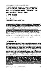
5 Hexi Cipher 5.1 Structure and Design of Hexi Cipher The mix column layer in the AES cipher design is replaced with a hexi coding layer in round nine to enable error detection and correction. This redesigned cipher is called as hexi cipher. Hexi cipher has ten rounds like the AES. Figure 1 gives the overall structure of the hexi cipher. Round function has four different stages, namely i. Substitute bytes / Inverse substitute bytes ii. Shift rows / Inverse shift rows iii. Mix column / Inverse mix column or Hexi coding /Hexi decoding iv. Add round key Rounds one to eight of the hexi cipher, perform the encryption procedure, round nine carries out the encoding procedure and round ten does substitute bytes, shift rows and add round key. The decoding and error correction is done in round one on the receiver side. Decryption is performed by the rounds two to nine; round ten does inverse substitute bytes, inverse shift rows and add round key. Each stage of the round function is described in detail.
Appl. Math. Inf. Sci. 7, No. 5, 2061-2069 (2013) / www.naturalspublishing.com/Journals.asp
2065
used during round nine of the hexi cipher to carry out encoding of the encrypted data. The last round does not have this stage at all. During decoding process, round one makes use of the hexi decoding which is described in Section 5.2 to decode and preform the error correction of the received data. Rounds two to nine of the decryption make use of the already existing inverse mix column, while the last round of the decryption does not make use of this stage.
5.2 Hexi Encoding and Decoding Hexi encoding and hexi decoding are discussed in detail.
5.2.1 Hexi Encoding The output from the 8th round, in a 4 × 4 representation of the cipher state will be of the form given below, where each sx,y , 1 ≤ x ≤ 4, 1 ≤ y ≤ 8 is an individual nibble of the state. s1,1 s1,2 s2,1 s2,2 s3,1 s3,2 s4,1 s4,2
Fig. 1: The Structure of Hexi Cipher
s1,3 s1,4 s2,3 s2,4 s3,3 s3,4 s4,3 s4,4
s1,7 s1,8 s2,7 s2,8 s3,7 s3,8 s4,7 s4,8
Any (4, 4) quasi cyclic partial hexi code will have its generator matrix G given by k1,1 k2,1 G= k3,1 k4,1
1. Add round key stage The key expansion algorithm of the AES is altered to suit the necessity of the hexi cipher. Since the last round and the encoding round of the hexi cipher makes use of 12 words for each key in this stage. The original key expansion algorithm of the AES is easily expandable. Hence the iterations are increased to 60, so as to produce 60 key words. 2. Substitute bytes stage / Inverse substitute bytes stage The substitute bytes stage and its inverse operation of each round of the hexi cipher are same as in AES, their functionality is left unaltered. 3. Shift row stage / Inverse shift row stage The shift row stage and its inverse operation of each round of the hexi cipher are same as in AES, their functionality is left unaltered, while in the last two rounds, it needs to deal with 4 × 12 representation of cipher state. 4. Mix column stage or Hexi coding stage / Inverse mix column stage or Hexi decoding stage In hexi cipher, rounds one to eight make use of the already existing mix column function. The hexi encoding function which is described in Section 5.2 is
s1,5 s1,6 s2,5 s2,6 s3,5 s3,6 s4,5 s4,6
k1,2 k2,2 k3,2 k4,2
k1,3 k2,3 k3,3 k4,3
k1,4 k2,4 k3,4 k4,4
kx,y ∈ S; 1 ≤ x, y ≤ 4. This 4 × 4 generator matrix G of any quasi cyclic partial hexi code is used instead of the MDS code that is used in AES. Each sx,y is encoded by sx,y .G resulting in a codeword of the form v1x,y v2x,y v3x,y v4x,y ; 1 ≤ x ≤ 4; 1 ≤ y ≤ 8. However only the first three terms namely v1x,y v2x,y v3x,y are utilized for the encoding. Any 4 × 4 quasi cyclic hexi code can be used, it can also work as secret key between the sender and receiver. The algorithm for encoding a message row of the output of the eighth round, takes four nibbles of the message row as the input and produces an output of 12 nibbles is given in Algorithm 1. For the sake of notational convenience, sx,y is taken as sy and s′x,y is taken as s′y as only one row is discussed. The process is repeated for the next four nibbles of the row. The output of the hexi coding function is of the structure given below s′1,1 s′1,2 s′2,1 s′2,2 s′3,1 s′3,2 s′4,1 s′4,2
s′1,3 s′1,4 s′2,3 s′2,4 s′3,3 s′3,4 s′4,3 s′4,4
s′1,5 s′1,6 s′2,5 s′2,6 s′3,5 s′3,6 s′4,5 s′4,6
... ... ... ...
s′1,23 s′1,24 s′2,23 s′2,24 s′3,23 s′3,24 s′4,23 s′4,24
c 2013 NSP
Natural Sciences Publishing Cor.
2066
K.Ilanthenral , K. S. Easwarakumar: Design of Hexi Cipher for Error...
Algorithm 1: E NCODE Algorithm for encoding
1 2 3 4 5 6 7 8 9 10 11 12 13 14 15
Input: s1 , s2 , s3 , s4 Output: s′1 , s′2 , s′3 , s′4 , s′5 , s′6 , s′7 , s′8 , s′9 , s′10 , s′11 , s′12 for j ← 1 to 12 do s′j ← 0 end begin for i ← 1 to 4 do if si 6= 0 then s′2i−1 ← s′2i−1 ⊕ v1 i s′2i ← v2 i s′2i+1 ← v3 i end end s′10 ← s′2 ⊕ s′4 ⊕ s′6 ⊕ s′8 s′11 ← s′3 ⊕ s′7 s′12 ← s′1 ⊕ s′9 end
Algorithm 2: D ECODEERROR Algorithm for decoding, error detection and error correction.
1 2 3 4 5 6 7 8 9 10 11
Input: s′1 , s′2 , s′3 , s′4 , s′5 , s′6 , s′7 , s′8 , s′9 , s′10 , s′11 , s′12 Output: msg rmsg ← s′1 , s′2 , s′3 , s′4 , s′5 , s′6 , s′7 , s′8 , s′9 , s′10 , s′11 , s′12 om ← rmsg begin rmsg ← D ECODE(rmsg, msg) y ← E RRORSTRING(rmsg) if y 6= 0 then om ← E RRORCORRECTION(y, rmsg, om) else No Error end end
The Decode procedure calls on Subtractcode which XORs the related codeword code[relx] with the received message i.e., rm. Note: The odd nibbles and even nibbles can be taken separately and worked out, instead of taking the first four nibbles. The encoding of the message is done using a lookup table like Table 3 for generator matrix G given in (4). The first term is encoded as s′1 , s′2 and s′3 , the second term is encoded as s′3 , s′4 and s′5 , i.e., s′3 is the XOR of the third term of the first codeword and the first term of the second codeword. Similarly s′5 and s′7 are XOR of first and third terms of successive codewords respectively. The even terms, namely s′2 , s′4 , s′6 and s′8 are dependent only on one codeword, s′10 serves as their parity byte, s′11 serves as the parity of s′3 and s′7 terms. Also s′12 serves as the parity of s′1 and s′9 terms. The resultant of the hexi encoding is 48 bytes, so the add round key of round ten requires 12 word key. The end result of the hexi cipher is 48 bytes.
Algorithm 3: D ECODE Algorithm for decoding the message
1 2 3
4 5 6 7
Input: rm, code Output: msg begin for i ← 1 to 4 do x ← rm[2 ∗ i] // Refer Table 3 // Where x = v2 i the related Hexicode code[relx][] = v1 i v2 i v3 i // relx = Related Message; msg[i] ← relx S UBTRACTCODE(code[relx][], rm[2 ∗ i − 1], rm[2 ∗ i], rm[2 ∗ i + 1]) end end
5.2.2 Hexi decoding, error detection and error correction The error detection and correction capacity of the hexi cipher is analysed. The receiving side will get the encrypted message, which may contain errors. When the hexi decoding of the message begins the message will contain errors due to the transmission in channel and errors which are propagated due to the decryption process. The generalised algorithm for decoding, error detection and error correction of the received message is given in Algorithm 2. It calls on the Decode procedure given in Algorithm 3, which takes the received message rm, decodes it, stores the decoded message in global variable msg and returns the reminder of the received message rm. The Decode procedure uses the even bytes of the received message, namely rm[2i], 1 ≤ i ≤ 4 to create msg. The related codeword of rm[2i] from the set of all codewords code (a two dimensional array of size [16][3]) is obtained.
c 2013 NSP
Natural Sciences Publishing Cor.
The related codeword of rm[2i] is obtained from the table of codewords where rm[2i] = v2 i , this related codeword is XORed with rm[2i − 1], rm[2i] and rm[2i + 1] to obtain the reminder. The decoded message msg is obtained from rm[2], rm[4], rm[6] and rm[8]. The remaining bytes of the message form the error string. The Errorstring procedure given in Algorithm 4 is to convert the rm to a string of 1’s and 0’s. If errorstring variable y = 0 then there is no correctable error detected, else error is detected and it calls on the Errorcorrection procedure for error correction. The Errorcorrection algorithm calculates the XOR of even bytes, XOR of rm[3] and rm[7] and the XOR of rm[1] and rm[9]. If the resultant XOR matches with its respective parity, then the parity variable (even, odd and odd1) is given value 0, else 1. Based on the error string, it is determined where error might have occurred. A sample
Appl. Math. Inf. Sci. 7, No. 5, 2061-2069 (2013) / www.naturalspublishing.com/Journals.asp
Algorithm 4: E RRORSTRING(rm). Algorithm for conversion of errorstring
1 2 3 4 5 6 7 8 9
Input: rm Output: y y←0 x ← 10000 begin for i ← 0 to 4 do if rm[2 ∗ i + 1] 6= 0 then y ← y + x x ← x / 10 end Return y end
Algorithm 6: E RRORCORRECTION(y, rm, om)
1 2 3 4 5 6 7 8 9 10 11
Algorithm 5: M AKECODE(X, Y ). Algorithm for creation of new codeword
1 2 3 4 5 6 7 8 9 10
Input: X Output: C[1..3] begin for i ← 1 to 16 do if X = code[i][Y ] then C[1] ← code[i][1] C[2] ← code[i][2] C[3] ← code[i][3] end end Return C end
12 13 14 15 16 17 18 19 20 21 22 23 24 25 26
table of the error string, possible error positions and the parity variables is given in Table 4. Since there are nearly over 400 such possibilities only a few cases are given and discussed. Depending on the parity variable and error string the algorithm creates a new set of codewords for the possible set of errors using Makecode procedure given in Algorithm 5. The Errorcorrection procedure checks if parity bytes are correct for the new set of codewords, if found correct it returns the new corrected message and exits; if else, checks for the next set of codewords. In case parity bytes are correct for the two sets of codewords, it quits since it is not able to find the correct corrected codeword. It repeats till the end of all possible errors, if none matches, it exits, since error correction is not possible. The Errorcorrection algorithm given in Algorithm 6 gives the error correction for a sample of subcases of possible errors for the error string ‘1’. For illustration; take a error string (1 0 0 1 0), the list of possible errors is given in Table 4. When all parity variables are 0, then the error has occurred in 2, 4 and 6 i.e., rm[2], rm[4] and rm[6]; (2, 4, 6). If all parity variables are 1, then the error has occurred in bytes 1, 7 and 10. When even is 0; the other parity variables are 0 or 1, then error has occurred at bytes 1 and 7 i.e., rm[1] and rm[7] or 1, 7, 11 or 1, 7, 12. In these cases where parity byte is wrong, it is enough to correct only bytes 1 and 7. When
2067
27 28 29 30 31 32 33 34 35 36 37 38 39 40 41 42 43 44 45 46 47 48
Input: y, rm, om Output: om even, odd, odd1 ← 1 begin if om[10] = om[2] ⊕ om[4] ⊕ om[6] ⊕ om[8] then even ← 0 if om[11] = om[3] ⊕ om[7] then odd ← 0 if om[12] = om[1] ⊕ om[9] then odd1 ← 0 switch y do case 1 if even = 0 then if odd = 0 and odd1 = 0 then ch1 ← MC(om[9], 3) ch2 ← MC((om[7] ⊕ ch1[1]), 3) ch3 ← MC(om[4], 2) om[8] ← ch1[2]; om[6] ← ch2[2] om[5] ← (ch2[1] ⊕ ch3[3]) break else om[9] ← (rm[9] ⊕ om[9]) break end else if odd = 0 then if odd1 = 0 then // 5,6,8; dealt as above else // 9,10 or 9,10,12 else if odd1 != 0 then if (om[1] ⊕ om[12]) = (rm[9] ⊕ om[9]) then // 9,10,11; else om[7] ← (om[3] ⊕ om[11]) ch1 ← MC(om[6], 2) ch2 ← MC((om[7] ⊕ ch1[3]), 1) om[8] ← ch2[2] om[9] ← ch2[3] break end else ch1 ← M C(om[9], 3) ch2 ← M C(om[6], 2) om[8] ← ch1[2] om[7] ← (ch1[0] ⊕ ch2[3]) break end end end Return om endsw .. . endsw end
c 2013 NSP
Natural Sciences Publishing Cor.
2068
Table 4: Possible errors for the error string variable Error String Possible Errors 1 5, 6, 8 1 9, 12 1 9 (or) 9, 12 1 9, 11, 12 1 7, 8, 10 1 9, 11 (or) 9, 11, 12 1 5, 6, 8 1 7, 8, 11 1 9, 10, 12 1 9, 10 (or) 9, 10, 12 1 7, 8 (or) 7, 8, 11 (or) 7, 8, 10 1 7, 8, 9 (or) 7, 8, 12 1 9, 10, 11 .. .. . . 10010 2, 4, 6 10010 1, 7, 11 10010 1, 7, 12 10010 1, 7 (or) 1, 7, 11 (or) 1, 7, 12 10010 1, 8, 9 10010 1, 5, 6 10010 2, 4, 6 10010 2, 3, 7 10010 1, 8, 9 10010 2, 3, 7 10010 1, 7, 10 .. .. . . 11111 1, 4, 8 11111 2, 6, 9
K.Ilanthenral , K. S. Easwarakumar: Design of Hexi Cipher for Error...
and their parity E 0 0 0 0 0 0 1 1 1 1 1 1 1 .. . 0 0 0 0 1 1 1 1 1 1 1 .. . 1 1
O 0 0 0 1 1 1 0 0 0 0 1 1 1 .. . 0 0 1 1 0 0 0 0 0 1 1 .. . 0 0
O1 0 0 1 0 0 1 0 0 0 1 0 1 1 .. . 0 1 0 1 1 1 0 0 0 0 1 .. . 1 1
If the error has occurred in the even bytes of the message row, then the even parity is affected, else if the error has occurred in the odd bytes of the message row, the odd parity bytes are affected. The position of the error is detected by the decoding of the message and the parity bits. Lemma 1.If error has occurred in bytes related to different parities or if more than one error occurs in bytes related to same parity, then there are cases where parity might not show the error, but in all cases the decoding shows the position of possible errors. Proof.The decoding process, recreates the message by using the even bytes, since they are independent of other codewords. This decoding process produces a error string. If there is no error, the error string is 0. In case of error, the associated odd bytes reflect the error. By the calculation of the parity variables, the possible position of error is detected. This is explained clearly in the given illustration. Theorem 3.In each row of the 4 × 12 representation of the cipher state, hexi decoding can detect all errors and correct maximum of 3 byte errors. Proof.By lemma 1 the hexi decoding process can detect the possible position of errors. By theorem 2 once the correct position is known, the whole codeword can be retrieved. The correctness of the message can be rechecked using the parity bits and the neighbouring bits. Thus the hexi cipher has a error correction capacity of nearly 25 percentage of errors.
odd is 0; and the other two parity variables are 1, the error has occurred at 1, 8, 9 or 1, 5, 6. First the error in byte 1 is removed by the XOR of first byte of rm and om. The parity variable odd1 is recalculated, if it is 0, then possible error is 1, 5, 6, else possible error is 1, 8, 9. Similarly the other cases are dealt, though the logic of handling errors works differently for different set of errors.
5.3 Error Correction Capacity of Hexi Cipher The error correction capacity and the correctness of the error correction of the hexi cipher is analysed in the following theorems. Theorem 2.Given one correct element and its position in the quasi cyclic partial hexi codeword, the whole codeword can be obtained. Proof.By Remark 1 and Remark 2 for any given quasi cyclic partial hexi CH (16,4) code there are only 16 codewords and these 16 codewords are cyclic and unique. So if the position of one correct element is known, the whole codeword can be retrieved.
c 2013 NSP
Natural Sciences Publishing Cor.
5.4 Implementation Features The implementation of the error detection and error correction of a received message row was carried out. Without loss of generality, the implementation works with the assumption that all the three parity bytes are correct and the errors are present in the message bytes alone. Since the error in the parity will not affect the decoding process. Assume the worst case scenario were the three parity elements are wrong, then it implies that there is no error in the message; hence error correction need not be done. In case, error is in two parity elements, then there is error in only one message element, which can be corrected. Else one parity element has error, then two message elements have error, and they can be corrected using normal error correction, without help of parity. Since handling nibbles is a tedious process, bytes have been used for the implementation. Any correct message is taken and errors are added to the message. Errors are randomly generated. The generator matrix used for implementation, is given in (4) and look up table for codewords is given in Table 3. In the implementation, decoding and error correction was done for the following
Appl. Math. Inf. Sci. 7, No. 5, 2061-2069 (2013) / www.naturalspublishing.com/Journals.asp
1. When the received message was same as the message that was sent, i.e., no error was introduced. Only decoding and error detection was done. 2. Error was introduced in only one byte, error detection and error correction was carried. There are only 9 such possible cases. 3. In two bytes, errors were introduced. 36 possible cases were handled; successful error correction was carried out. 4. Error was introduced in three bytes, there were 84 such possible combinations. Error detection and error correction was carried. The total 350 cases of errors, was grouped into 130 standard cases. These were dealt, error detection and error correction was successfully carried out in all cases, other than cases where the error added was itself a codeword, or when two set of errors satisfied the parity.
5.5 Comparison with other existing cipher The hexi cipher is as secure as the existing AES cipher, since only one round is altered. It has error correcting capacity of nearly 12 bytes of 48 bytes transmitted, whereas the AES has no error correcting. Hexi cipher is more space and time consuming. Hexi cipher has better error correcting capacity than existing error correcting ciphers like HD cipher and pyramid cipher. Hexi cipher corrects nearly 12 bytes of 48 bytes transmitted whereas HD cipher corrects 7 bytes of 36 bytes transmitted and pyramid cipher corrects 4 bytes of 24 bytes transmitted. The hexi cipher is an improvisation of the existing cipher, with better error correcting capacity.
6 Conclusion and further directions In this paper, hexi codes, hexi polynomial codes and quasi cyclic partial hexi codes are defined using the field S. Hamming metric and error correcting capacity of these codes are discussed. The hexi cipher is a modified version of the AES, with error detection and correction capacity. It is constructed using the CH (16, 4) quasi cyclic partial hexi codes in the mix column layer of round nine, instead of the MDS code used by the AES. Hexi cipher which has better error correcting capacity than existing ciphers like HD cipher and pyramid cipher. The hexi cipher corrects upon 3 bytes of 12 bytes of the message that is transmitted., i.e., 12 bytes of the 48 bytes transmitted as a state. It has a capacity of detecting 99% of errors and correcting nearly 25% of errors that occur. The hexi cipher is also capable of correcting some 4-byte and 5-byte errors. The percentage of error correction possible in case of 4-byte and 5-byte errors has not been studied yet. A study in this direction remains open.
2069
References [1] M. Ayyaz, Method to improve channel coding using cryptography, World Academy of Science, Engineering and Technology, 41, 525-528 (2008). [2] H. Cam, V. Ozduran and N. O. Ucan, A combined encryption and error correction scheme: AES-TURBO, Istanbul university Journal of Electrical and Electronic Engineering, 9, 891-896 (2009). [3] N. M. Chetan, A Mathematical framework for combining error correction and encryption, Ph.D. diss, Stevens Institute of Technology, Hoboken, NJ, USA, (2007). [4] M. Czapski and M. Nikodem, Error detection and error correction procedures for the advanced encryption standard, Des. Codes Cryptography, 49, 217-232 (2008). [5] J. Daemen, and V. Rijmen, The Design of Rijndeal, AESThe Advanced Encryption Standard, Springer, (2002). [6] R. Elumalai and A. R. Reddy, Improving diffusion power of AES Rijndael with 8 × 8 MDS matrix, International Journal of Scientific & Engineering Research, 2, 1-5 (2011). [7] T. K. Moon, Error Correction Coding- Mathematical Methods and Algorithms, Wiley, (2005). [8] J. Nakahara and E. Abrahao, A new involutory MDS matrix for the AES, International Journal of Network Security, 9, 109-116 (2009). [9] S. Lin and D. J. Costello, Error Control Coding, Pearson, (2005).
Ilanthenral Kandasamy is currently pursing her PhD under the guidance of Prof. K. S. Easwarakumar at Department of Computer Science and Engineering at Anna University, Chennai. She received her B.Sc. in Mathematics from Madras University, Chennai, Master of Computer Science and Application from Anna University, Chennai. Her research interests include Cryptography and Coding Theory. K. S. Easwarakumar is a Professor at the Department of Computer Science and Engineering at Anna University, Chennai. He received his M.Tech in Computer and Information Sciences from Cochin University of Science and Technology, Cochin and Ph.D in Computer Science and Engineering from Indian Institute of Technology, Madras. His research interests include parallel and distributed computing, Data Structures and Algorithms, Graph Algorithms, Parallel Algorithms, Computational Geometry, Theoretical Computer Science and Molecular computing.
c 2013 NSP
Natural Sciences Publishing Cor.