nitride. An Al current strap was buried beneath the channel and shaped in such a way to generate an in-plane cross-channel field gradient when it was ...
Design of Integrated Microfluidic Device for Sorting Magnetic Beads in Biological Assays Mark Tondra1 , Mike Granger2 , Rachel Fuerst2 , Marc Porter2 , Catherine Nordman1 , John Taylor1 , and Seraphin Akou1 , 1 NVE Corp., 11409 Valley View Rd., Eden Prairie, MN 55344 2 Microanalytical Instrumentation Center, 41 Spedding Hall, Iowa State University, Ames, IA 50011
Abstract -- On-chip manipulation of nanoscopic magnetic particles in microfluidic channels has been demonstrated. The particles, obtained from Bangs Labs, were 460 nm in diameter and contained 12% ferrite. They were moving in a 12 µm wide by 4 µm deep channel etched into a deposited layer of silicon nitride. An Al current strap was buried beneath the channel and shaped in such a way to generate an in-plane cross-channel field gradient when it was energized by an electrical current. An in-plane external field of 20 kA/m was applied in order to magnetize the particles. They were observed to move across the channel as either the current or field polarity was changed.
I.
INTRODUCTION
There is a continuous push to miniaturize and integrate as many laboratory instrumentation pieces as possible in the quest for a “lab on a chip”. Micron sized magnetizable beads play an important role in this quest because they are a common tool for separating or concentrating a target species from a fluid. This is because the surfaces of the beads can be “functionalized” by attaching specialized surface coatings that cause them to be chemically attractive for certain chosen biochemical molecules. The range of possible functionalizations includes DNA [1], proteins, and bacteria [2]. Several manufacturers supply prefunctionalized magnetizable beads for a wide range of applications. Related uses for this general technology include fractionation of “magnetic fluids,” which generally are more magnetic than the paramagnetic particles discussed here [3]. This paper does not treat a specific assay or fractionation application, but rather focuses on the micromagnetic design of an integrated sorter for any such magnetizable beads. An integrated magnetic bead sorter combines micromagnetics with microfluidics. A magnetic environment must be created where particles with distinct magnetic properties may be manipulated differently than other particles in a controlled fluid. The common approach is to use the force of a magnetic field gradient on a magnetized bead to move the beads with respect to some fluid flowing in a microfluidic channel. Related devices have been discussed in the literature. In some cases, stray fields from a permanent magnet placed near the channel are used to manipulate the beads [4-6]. In other cases, an integrated solenoid is used to apply a local
field to the beads in a channel [7]. Several practical difficulties arise in these devices. Permanent magnets are not easily positioned with respect to a channel and impose a size scale well beyond the otherwise tiny microfluidic channels. Integrated coils are notoriously difficult to fabricate, and also result in fairly large structures. In both cases, there is no way to create repulsive forces. This paper describes a magnetic field configuration that both simplifies fabrication and permits the region of applied force to be highly localized (on the same scale as the microfluidic channels). It does not require permanent magnets and is highly controllable through the adjustment of on-chip currents through integrated current straps. The key idea is that a nominally uniform external magnetic field can be used to magnetize the beads while integrated current straps can be used to generate large and highly localized field gradients. A mathematical description of the micromagnetic design is presented. A preliminary demonstration of this localized sorting device is described, as well as the fabrication and preparation of the microfluidic channel, integrated current straps, and sealed cover and interconnects for the channel. II.
FORCE ON A MAGNETIZABLE OBJECT IN A GRADIENT
The force that can be applied on a magnetized bead is proportional to the object’s magnetization and the gradient in the field parallel to that magnetization. Ferromagnetic objects may have significant magnetization even in the absence of an applied field. Typical assay beads, however, are paramagnetic. This means each bead’s magnetization is parallel to and linearly proportional to the applied field. Using SI units: B = µo ( H + M ) M = χ m H app
(1) (2)
Units : Wb/m 2 = (Henries/m)(Amps/m)
Here χm is the dimensionless magnetic susceptibility and the beads are being magnetized by a uniform external field H app . For convenience, we assume a spherical superparamagnetic or ferromagnetic particle along the lines of
Dynal’s M280 bead which has a diameter of 2.8 µm and a χm of about 0.05. A field along the x-axis will uniformly magnetize a bead to magnetization M x , and induce a dipole moment p: p = ( 4π / 3) a 3 M
(3)
where a is the radius and M is the magnetization. The force on the dipole p due to a magnetic field gradient is F = µo ∇(H • p)
(4)
Suppose the local magnetic field distribution in the region of the bead is such that H x >> H y , H z and ∂H/ ∂x >> ∂H/∂y, ∂H/∂z (large and relatively uniform in the xdirection). Then the force on the bead is closely approximated by Fx = µ o ∂H/ ∂ x • p ≈ χ m µ o H x (∂ H/ ∂x )( 4π / 3)a 3
(5)
Easily achievable on-chip values for H and ∂H/ ∂x are 10 4 A/m and 2 ×10 8 A/m 2 , respectively. Also, a = 10 −6 m, and χm = 0.05 . So a typical force would be F = (0 .05)( 4π ×10 × ( 4π / 3)(10 = 53 × 10
−14
−18
−7
H/m)(10 A/m)(2 ×10 A/m ) 4
3
m )
8
2
(6)
Newtons= 530 fN
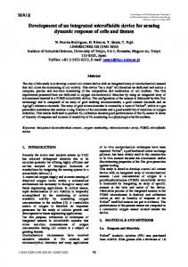
For reference, assuming a bead has a mass density of 10 times water, a bead with a diameter of 1 µm will experience a gravitational force 51 fN: the magnetic force on the bead is ten times greater than that from gravity. The values used for this calculation are fairly conservative. One could clearly increase the expected force on magnetizable particles by several orders of magnitude by increasing the external field, the gradient field, and the particles’ susceptibility and volume. 1) Sorter Design As noted above, conditions for applying magnetic force on a particle are achieved by combining a uniform external field with an on-chip field gradient. In order for this force to be useful for a magnetic fluid sorter, these two field conditions must coincide with a region where a microfluidic channel splits. Schematics of a simple integrated magnetic flow sorter are shown in Figures 1 and 2.
Figure 1: Cross–section view of an integrated magnetic sorter. This view is from the left side of Figure 2. The drawing is approximately to scale. The field generated is indicated by the circles around the buried straps. The indicated dimensions can be scaled up or down depending on what size particles are being used, the viscosity of the fluid, the conductivity and process tolerance of the buried metal, and other factors. An external field is applied from left to right to magnetize the bead.
The basic concept is to have electrical current going in opposite directions in two adjacent buried metal straps. These straps pass beneath a microfluidic channel such that they run parallel to and on either side of the channel in a region where the channel splits. When a magnetized particle passes over the sorter, it experiences a cross-channel force proportional to the strap current. This is because the field from these straps just above them has a large cross-channel gradient that is proportional to the strap current. The particle is attracted to and repelled by fields parallel and opposite to its magnetization, respectively. In order for the sorter to truly work, the force on the particle must be large enough to push it to one side of the channel within the time the particle is in the sorter region (before the channel split). The chance of a given magnetized object being “sorted” can be increased by: 1) extending the sorting region up the channel (make the strap fork start well before the channel split), 2) increasing the current through the strap, 3) decreasing the flow rate in the channel, and 4) increasing the magnetization of the object. Conversely, the chances of an object being sorted can be decrease by doing the opposite things (shorter sorting region, lower current, higher flow rate, decreased magnetization).
Figure 2: Top schematic view of an integrated magnetic sorter. The fluid carrying magnetizable particles flows from right to left. In-plane magnetized (up or down) objects in the fluid experience a force towards the leg of the current strap that generates a field parallel to the particle’s magnetization. The in-plane component of the force is indicated by F. If the current direction changed in the strap, the force reverses direction.
One important design aspect not shown clearly here is that the portion of the strap that crosses under the channel should be much wider than the portions parallel to the channel. Then the current density (and therefore the force) is much smaller in the cross-under region. 2) Magnetic Particle Properties Because the magnetization of a particle is directly related to its magnetic properties, it is possible to sort out particles of differing magnetic properties. One could vary the magnetization of the particles by changing the susceptibility, or the fractional composition of magnetic material (many magnetizable particles have a core of magnetic material surrounded by a non-magnetic coating, or a matrix of magnetic and non-magnetic material). Additionally, the force required for a successful “sorting event” is proportional to a particle’s cross sectional area, because the force must move the particle through the fluid. So the magnetization per unit crosssectional area will also determine whether a particle is sorted or not. Thus, there are several ways to create sorters that not only separate magnetic from non-magnetic objects, but also sort varying magnetic objects by their specific properties. III.
EXPERIMENTAL AND DISCUSSION
Buried metal sorter lines were fabricated beneath microfluidic channels patterned into Si 3 N 4 . The channels were then covered with specially patterned PDMS (Poly(dimethylsiloxane)) caps. Polyimide coated fused silica capillaries (350 µm OD, 250 µm ID; Polymicro Technologies, AZ) were inserted from the side of the PDMS into the chambers. The inlet capillary was connected to a syringe and the outlet capillary was placed in a vial. Constant pressure applied to the syringe induced fluid flow through the Si 3 N 4 channel, through the outlet capillary, and the fluid was collected in the vial.
Non-quantitative aqueous suspensions of magnetic beads were then introduced to the fluidic network. The bead specifics were: 0.460 µm diameter Fe 2 O 3 beads (11% magnetic material by weight; MC03N, Bang Labs). The beadand-water suspensions were allowed to flow through the channels and over the sorter regions. These beads are superparamagnetic and require a magnetic field to induce a magnetic dipole within them. To this end, an external field (H) of 20 kA/m was applied in the plane of the chip but perpendicular to the flow direction in the sorter. A plug of the suspended beads was allowed to come to rest over the magnetic sorter (see device list and design purpose section). With no applied current through the sorter the magnetized beads adopted a striated pattern across the channel commensurate with the magnetic field lines of the external magnet. Passing 10 mA through the sorter acted to drive the beads to one wall of the channel. Reversing the polarity of the current reversed the side of the channel that the beads were driven towards. This motion could be repeated indefinitely over a wide spectrum of frequencies. Further experiments to realize the sorting of beads in a moving stream were hindered by an unexpected blockage of the channel and the inability to move the beads further by hydrodynamic methods. The nature of the blockage is not known at present as no visual identifications could be made. It is thought that PDMS detritus, created during the insertion of the capillaries, could have been carried into the channel by the aqueous suspension of the beads and be responsible for the blockage. VI.
CONCLUSION
The variable magnetic material sorting feature has many uses. Clearly, it can be used to create a sample of monodisperse magnetized objects. If certain chemical or biological species are attached to the magnetizable particles, the sorter can be used to move these species in a controlled way. In fact, a magnetic particle with a known species attached to it can be thought of as the world’s smallest container. Because small particles can be coated with “functionalizing groups” which determine what species will stick to it, one can prepare a volume of a desired species consisting of only the surface area of one magnetic particle. Then with the sorting apparatus, this “nano-beaker” can be manipulated in the channels and directed to a desired reaction chamber. It is often desirable to mix together two different fluids flowing in the same channel. This can sometimes be difficult due to the laminar type flow that is present in typical microfluidic system where the Reynolds number is well under that required for turbulent flow. The same structures used to sort and pump could be used to induce mixing. A simple example would be to use the sorter strap under a single (not splitting) channel, and oscillate the current in the strap so that any magnetizable particles in the channel are forced from side to side at the frequency of oscillation. If mixing is the primary
objective, particles with susceptibility much higher than the typical 0.05 could be used. These mixing ideas are microscopic analogies to standard macroscopic mixing capsules and rotating magnetic fields. Though significant effort is required to fully realize the intended use of the described magnetic sorting device, its potential has been well demonstrated. Of particular importance is the fact that the required magnetic field distributions are highly localized and are consistent with having many other magnetic functions on the same chip. Of particular interest is the combining of integrated sorting functions with magnetic modes of detection and analysis [811]. V. [1]
REFERENCES
Z. H. Fan, S. Mangru, R. Granzow, P. Heaney, W. Ho, Q. Dong, and R. Kumar, “Dynamic DNA Hybridization on a Chip Using Paramagnetic Beads,” Anal. Chem., vol. 71, pp. 4851-4859, 1999. [2] N. Nakamura, J.G. Burgess, K. Yagiuda, S. Kudo, T. Sakaguchi, and T. Matsunaga, “Detection and Removal of Escherichia coli Using Gluorescein Isothiocyanate Conjugated Monoclogal Antibody Immobilized on Bacterial Magnetic Particles,” Anal. Chem., vol. 65, pp. 2036-2039, 1993. [3] T. Rheinlander, J. Justiz, A. Haller, R. Kotitz, W. Weitschies, W. Semmler, “Dynamic Properties of Fractions Yielded by Magnetic Fractionation of Magnetic Fluids,” IEEE Trans. Magn., vol. 35, pp 4055-4057, 1999. [4] G. Blankenstein, “Microfabricated Flow System for Magnetic Cell and Particle Separation,” Scientific and Clinical Applications of Magnetic Carriers, Plenum Press, pp. 223-246, 1997. [5] M. Zborowski, L.R. Moore, L.Sun, J.J. Chalmers, “Continuous-Flow Magnetic Cell Sorting Using Soluble Immunomagnetic Label,” Scientific and Clinical Applications of Magnetic Carriers, Plenum Press, pp. 247-258, 1997. [6] C.B. Fuh, “Split-flow Thin Fractionation,” Anal. Chem., pp. 266A – 271A, April 1, 2000. [7] C. Ahn, unpublished. [8] C.B. Kriz, K. Radevik, and D. Kriz, “Magnetic Permeability Measurements in Bioanalysis and Biosensors,” Anal. Chem., vol. 68, pp. 1966-1970, 1996. [9] R. Kotitz, H. Matz, L. Trahms, H. Koch, W. Weitschies, T. Rheinlander, W. Semmler, T. Bunte, “SQUID Based Remanence Measurements for Immunoassays,” IEEE Trans. Appl. Supercond., Vol. 7, pp. 3678-3681, 1990. [10] D.R. Baselt, G. U. Lee, M. Natesan, S. W. Metzger, P. E. Sheehan, and R. J. Colton, Biosensors and Bioelectronics, vol. 13, p. 731, 1998. [11] M. Tondra, M. Porter, R. J. Lipert, “Model for Detection of Immobilized Superparamagnetic Nanosphere Assay Labels Using Giant Magnetoresistive Sensors,” J. Vac. Sci. Technol. A, vol. 18, pp. 1125-1129, 2000.