ISSN (Print) : 2319-8613 ISSN (Online) : 0975-4024
I.B. Alit Swamardika et al. / International Journal of Engineering and Technology (IJET)
Design of Mobile Robot with Robotic Arm Utilising Microcontroller and Wireless Communication I.B. Alit Swamardika #1, I N. Budiastra #2, I N. Setiawan #3, N. Indra Er #4 #
Department of Electrical and Computer Engineering, Udayana University, Bali - Indonesia 1
[email protected] 2
[email protected] 3
[email protected] 4
[email protected]
Abstract—The purpose of this study is to design a prototype of a mobile robot equipped with a robotic arm which can be controlled by wireless technology. In this scheme, the mobile robot in the form of 6 Wheel Drive Robot equipped with robotic arm 6 Degree of Freedom and is controlled wirelessly through remote control based on XBee Pro Series 1. Data on the remote sent serially via XBee transmitter, processed on the receiver, and then used as a reference to control the robot. The tests on the forward, backwards, turn left, turn right, stop and linear movement of the robot was performed successfully, which elevates the robot deployment potentials. Keyword-Mobile robot, 6WD robot, Robotic arm 6 DOF, Robot remote control, Xbee pro I. INTRODUCTION The development of robotics technology basically aims to assist humans in performing a particular job, and it is a very fast evolving research field today. Some specific kinds of robots that can ease human task are mobile robots, the arm robot (manipulator robot), or a combination of both. Mobile robots are widely used for faster movement, especially on wheels. Arm robots are designed to hold, lift and move objects. While combining the two obviously aims to equip the robots with all the functions. The robotic systems can be controlled manually using a system of data transmission via cable, or via a wireless connection and several studies on this approach have been done before. A research in [1] constructs a mobile robot system modelling with Type-2 Fuzzy Logic control strategies based systems. Another in [2] describes the design and control the robot with two arms and has 7 Degree of Freedom (7 DOF). A study in [3] designed a robot arm with 4 DOF to perform the act of holding, lifting, placing and releasing objects individually. A research in [4] designed a mobile robot manipulator which can be controlled through wireless technology, and another in [5] designed robot with 6 wheels drive containing gas sensors used to detect dangerous gas leaks. Related to the works above, this research aims to design a robot with six-wheel-drive (6WD) which include six degree of freedom (6DOF) robotic arm that can be controlled through wireless technology. II. STATE OF THE ART A. Definition of Robotics The term robot was first introduced in English in 1921 by a Czechoslovakian playwright named Karel Capek in his play titled R.U.R (Rossum's Universal Robots). Robots in the earlier sense are "forced labour" which means slave labour, but in the modern sense of the word, the robot has undergone extension of meaning. According to The Robotics International Division of The Society of Manufacturing Engineers (RI/SME), the robot can be defined as "a reprogrammable and multifunctional manipulator designed to move material, parts, tools, and specialised devices through variable programmed motions for the performance of the variety of tasks". From the above, there are three keywords that show characteristics of a robot, which are: reprogrammable, multifunctional, and able to move material, parts, or tools (defined task manipulator). So the definition of robots, especially industrial robots is a multifunctional device designed to manipulate and transform tools or devices across a track that has been programmed to complete specific tasks. To be called as a modern robot system, a machine comprises at least three main things: 1) Manipulator. A manipulator is a mechanical unit that performs the functions of the movement. In the robot, manipulator normally consists of a sleeve (main frame) and wrist. The function of this manipulator is to allow the robot to reach a certain position with precision.
DOI: 10.21817/ijet/2017/v9i2/170902170
Vol 9 No 2 Apr-May 2017
838
ISSN (Print) : 2319-8613 ISSN (Online) : 0975-4024
I.B. Alit Swamardika et al. / International Journal of Engineering and Technology (IJET)
2) Actuator. Serves as a source of energy to drive manipulator. Actuators on the robot can be hydraulic systems, pneumatic systems, DC motors, AC motors, stepper motors and various types of other drivers. 3) Processor. Is the brain of the robot, serves to store and process every sequence of movements on the robot. Typically, the processor enables the robot to perform a variety of tasks programmed to it. B. Arduino Mega 2560 Arduino Mega 2560 is a microcontroller board that uses Atmega2560 as its main component. It has 54 pin digital I/O (14 pins can be used as PWM), 16 analogue input pins, 4 UARTs (serial communication), 16 MHz crystal, a USB connection, DC power Jack, ICSP header, and a reset button [6].
Fig. 1. Arduino Mega2560 [6]
Mega2560 Arduino can be powered through a USB connection or by an external power supply, and the power source is selected automatically. It can be operated at a voltage of 6V to 20V. When the input voltage is less than 7V, then the pin release voltage will be less than 5V. While when the input voltage is more than 12V, the voltage regulator IC will become very hot and which make it dangerous for the board. Therefore, the recommended input voltage is between 7V to 12V.
Fig. 2. XBee-Pro [7] (a) Module dimensions (b) Front view
C. Wireless XBee-Pro Serial Communications XBee-PRO is a module that allows the microcontroller to communicate by means of a ZigBee wireless standard protocol. ZigBee operates on the IEEE 802.15.4 physical radio and operates at 2.4 GHz unlicensed band. XBee-PRO modules will be loaded by a current of 250 mA while sending data (Tx) and 50 mA when receiving (Rx), with coverage of 100 meters (indoor) and 1500 meters (outdoor) [7]. The XBee-PRO can be seen in Figure 2. D. Robotic arm control configuration The design of the arm robot used in this research is the design of robotic articulation. This design has been selected due to the fact that the angle that can be explored by the end effector are very wide. Furthermore, this kind of robotic arm has a structure that resembles a human arm.
DOI: 10.21817/ijet/2017/v9i2/170902170
Vol 9 No 2 Apr-May 2017
839
ISSN (Print) : 2319-8613 ISSN (Online) : 0975-4024
I.B. Alit Swamardika et al. / International Journal of Engineering and Technology (IJET)
Fig. 3. Design for the degree of angle on the robotic arm
A robotic arm designed in our work have six degrees of freedom (6 DOF). An illustration of the movement system configuration in the form of the number of degrees of freedom can be seen in Figure 3. E. Infra Red Infrared is a beam of electromagnetic radiation with a wavelength of about 700 nm up to 1 mm, with a maximum current of 100 mA. Its wavelength is longer than visible light but shorter than radio wave radiation. With this, the wavelength of infrared light will not be visible to the eye, but the radiation and the heat produced by the infrared can be felt or detected.
Fig. 4. The Adjustable Infrared Sensor
F. Servo Motor Servo motor is a DC motor with a closed feedback system in which the position of its rotor will be communicated back to the control circuit in the servo motor. This motor consists of a DC motor, a set of gear, potentiometer, and the control circuit. Potentiometer serves to define the limits of the angle of rotation servo. While the angle of the axis servo motors regulated by pulse width signal sent through the legs of servo motor cables.
Fig. 5. Servo Motor
DOI: 10.21817/ijet/2017/v9i2/170902170
Vol 9 No 2 Apr-May 2017
840
ISSN (Print) : 2319-8613 ISSN (Online) : 0975-4024
I.B. Alit Swamardika et al. / International Journal of Engineering and Technology (IJET)
III. DESIGN METHODS A. Materials and tools Materials used in the design of hardware, among others: 1) Microcontroller Arduino Mega 2560 as a data processor and robot controllers. 2) Wireless communications module XBee-PRO as sender and recipient of the data instructions. 3) Gas sensor TGS 2600 as the main sensor in this study. 4) Nanotech Polymer Linear Battery 3 Cell 2800 mAh 2 pieces. 5) DC motors as actuators driving the rotation. 6) Motor servo actuator 180 degrees as robot arms. 7) An adjustable Infrared sensor as the detection object. 8) SSC-32 as a driver of overall servo motors. 9) The components of electronics, cables, PCB (Printing Circuit Board), lead and connectors. B. Software The supporting softwares used in our work are: 1) Basic programming language Compiler with AVR microcontroller programming language standards [8,9]. 2) Eagle 6.0 is used to create a circuit schematic created. 3) The Arduino IDE is used to create the program in the microcontroller. 4) X-CTU is used to configure the XBee. 5) Adobe Photoshop for editing test results. C. Hardware design The general description of the system are can be observed on block diagram in Figure 6.
Fig. 6. The System Block Diagram
DOI: 10.21817/ijet/2017/v9i2/170902170
Vol 9 No 2 Apr-May 2017
841
ISSN (Print) : 2319-8613 ISSN (Online) : 0975-4024
I.B. Alit Swamardika et al. / International Journal of Engineering and Technology (IJET)
Fig. 7. 6WD mobile robot with additional 6DOF robotic arm
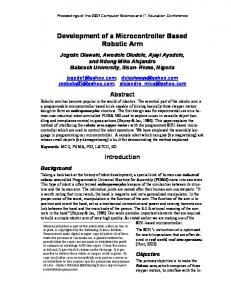
IV. RESULTS AND DISCUSSION A. Design Realisation Realisation of the 6WD Robot with the addition of a robotic arm to move objects which block its movement can be seen in Figure 7, while Table 1 showed the robot specifications. TABLE I. The Robot Specifications
No 1 2 3 4 5 6 6 7 8 9 10
Specifications Height Length Width Weight Motor Battery Mikrocontroller Batt. Mikrocontroller type Gases Sensor type Number of Gases Sensors Movement type Arm Robot type
Value 38 cm 42 cm 30 cm 5,1 kg 11,1 VDC 2,8A 11,2 VDC 1A ATmega2560 TGS2600 3 Front, 3 Back 6WD 6 Servo
B. Testing results of the microcontroller circuit Tests for the microcontroller circuit design, to determine whether microcontroller circuit is ready for use, were conducted as follows: 1. Checking the PCB track. 2. Testing Program Download from a PC to the circuit using the Arduino IDE, as shown in Figure 8. C. Actual results for the testing with the XBee XCTU Communication Software In Figure 9, it can be seen that the XBee connected to Com Port 5 with Baud rate of 9600 for receiving data. In the configuration, there is also a default Mac address assigned randomly by the software XCTU. In this particular connection, the Mac address obtained was 0013A200409EDD67.
DOI: 10.21817/ijet/2017/v9i2/170902170
Vol 9 No 2 Apr-May 2017
842
ISSN (Print) : 2319-8613 ISSN (Online) : 0975-4024
I.B. Alit Swamardika et al. / International Journal of Engineering and Technology (IJET)
Fig. 8. Circuit Testing for The Arduino Mega Microcontroller
Fig. 9. Xbee Testing with XCTU
D. Infrared Sensor Testing The testing of the infrared sensor was done using a hand as the obstacle. When the sensor did not detect an obstacle, the LED indicator light in the body of the sensor was not turned on. While when the sensor detected an obstacle, the indicator light turned on and then data was sent to the remote, consequently turned on the LED on the remote. Figure 10 to 12 showed the testing process.
Fig. 10. Infrared sensor testing without obstacle
Fig. 11. Infrared sensor testing in the presence of obstacle (hand)
DOI: 10.21817/ijet/2017/v9i2/170902170
Vol 9 No 2 Apr-May 2017
843
ISSN (Print) : 2319-8613 ISSN (Online) : 0975-4024
I.B. Alit Swamardika et al. / International Journal of Engineering and Technology (IJET)
Fig. 12. LED indicator testing for the Infrared on the remote
Fig. 13. PWM testing with the osciloscope
E. PWM Motor Testing on The robot As the signal width (duty cycle) and the frequency of the receiver were known, then the next step was to generate PWM signal that resembles the output signal from the Arduino to the motor driver. Tests on the output current signal have to be done directly on the output, in order to see the results of the frequency of the PWM pulse generation. Figure 13 showed the testing process using the PWM signal generation library servo on Arduino mega 2560, while Table 2 showed the output voltage measurements. TABLE II. PWM testing result on the arduino output pin with the osciloscope
PWM Arduino 80 100 150 200 250 255
Output Voltage on the arduino pin 0,95 V 1,89 V 2,86 V 4,79 V 4,75 V 4,84 V
Output Voltage on the driver motor 5,95 V 8,34 V 9,35 V 10,24 V 10,61 V 10,73 V
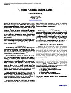
F. Realisation and testing on the remote control for the arm robot The command functions from the remote control to the robot currently can only be indicated by the direction of the remote stick and movement of the robotic arm. The division of these functions are as follows: a) Joystick y-axis range 0 to 500 functioned to move the robot reverse. b) Joystick y-axis range of 550 to 1023 functioned to move the robot forward. c) Joystick x-axis range 0 to 500 functioned to move the robot to the left. d) Joystick x-axis range of 550 to 1023 functioned to move the robot to the right. e) Potentiometer 1 functioned to drive the first servo motor to rotate the robotic arm. f) Potentiometer 2 functioned to drive the second servo motor to move the robotic arm up and down. g) Potentiometer 3 functioned to drive the third servo motor to move the elbow of the robotic arm up and down. h) Potentiometer 4 functioned to drive the second servo motor to make the robotic clamp arm clamp go up and down on. i) Potentiometer 5 functioned to drive the second servo motor to rotate the robotic clamp arm clamp.
DOI: 10.21817/ijet/2017/v9i2/170902170
Vol 9 No 2 Apr-May 2017
844
ISSN (Print) : 2319-8613 ISSN (Online) : 0975-4024
j)
I.B. Alit Swamardika et al. / International Journal of Engineering and Technology (IJET)
Potentiometer 6 functioned to drive the second servo motor to make the robotic clamp arm do the clamping.
Fig. 14. Remote controlling of the mobile robot with the robotic arm
V. CONCLUSIONS The conclusions of the work are as follows: 1. The Six Degree of Freedom (6 DOF) has enabled the robotic arm to perform the designed movements very well. Furthermore, the mobile robot successfully follows the command from each input variable resistors via the remote control to move the robotic arm. 2. The mobile robot and the robotic arm movement can successfully be done simultaneously, which elevates its potentials for deployment. ACKNOWLEDGMENT This work was supported by a research grant from Directorate General of Higher Education (DIKTI), Indonesian Ministry of Research, Technology and Higher Education, Indonesia. REFERENCES [1] [2] [3]
[4] [5]
[6] [7] [8] [9]
Siti Nurmaini, Anggina P., “Modeling of Mobile Robot System with Control Strategy Based on Type-2 Fuzzy Logic”, International Journal of Information and Communication Technology Research. Vo. 2 No. 3, 2012. Jebli Tarek, Zaoui C., Aref M. , “Design and Control of A Dual-Arm Robot”, International Journal of Latest Research in Science and Technology. Vol 4. Issue 6; p. 110-116, November –December 2015. Ravikumar Mourya, Amit S., Sourabh S., Sushant K. Manoj B., “Design and Implementation of Pick and Place Robotic Arm”, International Journal of Recent Research in Civil and Mechanical Engineering (IJRRCME). Vol. 2 Issue 1, pp: 232-240, AprilSeptember 2015. Zaenurrohman, Utis Sutisna., “Perancangan sistem kontrol wireless pada mobile robot manipulator berbasis mikrokontroler ATMega8”, Jurnal Nasional Teknik Elektro dan Teknologi Informasi (JNTETI), Vol; 3, No. 1. Februari 2014. Swamardika, I.B.A., Budiastra, IN., Setiawan IN. Yogi H., M., I P Adinata M.P., “Rancang Bangun Robot 6WD sebagai Alat Pendektesi Kebocoran Gas Berbasis Komunikasi Wireless XBee-Pro Seriel 1 60mW”, Majalah Ilmiah Teknologi Elektro. Vol.14 No.1, 2015. ArduinoTM. (t.t.). Arduino Mega 2560. [Online]. Available: https://www.arduino.cc/en/Main/ArduinoBoardMega2560. Accesed October 14, 2016. Digi International. XBee® & XBee-PRO® Datasheet. [Online]. Available: https://www.sparkfun.com/datasheets/Wireless/Zigbee/Xbee-Datasheet.pdf. Accessed October 14, 2016. Agung Seputra, Y.E., Buku Pintar Pemrograman C#. Yogyakarta: Mediakom. 2013. Sianipar, R.H., Pemrograman Visual C#. Bandung: Informatika. 2014.
DOI: 10.21817/ijet/2017/v9i2/170902170
Vol 9 No 2 Apr-May 2017
845
ISSN (Print) : 2319-8613 ISSN (Online) : 0975-4024
I.B. Alit Swamardika et al. / International Journal of Engineering and Technology (IJET)
AUTHOR PROFILE
Dr. Alit Swamardika is an Associate Professor in the Department of Electrical and Computer Engineering at Udayana University, Bali - Indonesia. He has 22 years of teaching experience for undergraduate and postgraduate courses in electrical and computer engineering. He received his B.E. in 1992, M.Erg. in 2001 and his Doctoral degree in 2012 from Udayana University. Currently he is also the Secretary for the Doctoral Program in Engineering at Udayana University, Bali – Indonesia. Mr. Budiastra is a Senior Lecturer in the Department of Electrical and Computer Engineering at Udayana University, Bali – Indonesia. He received his B.E. Control Systems in 1992 and M.E. in Power Systems Engineering in 2006 from Sepuluh Nopember Institute of Technology (ITS), Surabaya – Indonesia. He is currently the Vice Dean for Student Affairs in the Faculty of Engineering at Udayana University, Bali – Indonesia.
Mr. Setiawan is a Senior Lecturer in the Department of Electrical and Computer Engineering at Udayana University, Bali – Indonesia. He received his B.E. in 1990 and M.E. in Power Systems Engineering in 1999 from Sepuluh Nopember Institute of Technology (ITS), Surabaya – Indonesia. He is currently pursuing Doctoral degree in Electrical Engineering in the Faculty of Engineering at Udayana University, Bali – Indonesia.
Mr. Indra Er is a Lecturer in the Department of Electrical and Computer Engineering at Udayana University, Bali – Indonesia since 2002. He received his B.E. in Telecommunications Engineering in 1998 from Sepuluh Nopember Institute of Technology (ITS), Surabaya – Indonesia. He then obtained his M.Sc. in Communications Engineering from University of Birmingham, United Kingdom in 1999. Currently, he is pursuing Doctoral degree in Telecommunications for Information Technologies at Institute Mines Telecom, IMT-Atlantique, Rennes – France.
DOI: 10.21817/ijet/2017/v9i2/170902170
Vol 9 No 2 Apr-May 2017
846