TELKOMNIKA, Vol. 11, No. 8, August 2013, pp. 4651~4655 e-ISSN: 2087-278X
4651
Design of the Temperature Control System with the MicroLogix Sui Tao*, Sun Fanchao, Li Lijun, Liu Ruijuan, Qi Ranran Shandong University of Science and Technology, Qingdao, 266510, China *Corrsponding author, e-mail:
[email protected]
Abstract The design and verification of accurate temperature control system of the oven with the small or middle scale programmable logic controller (PLC) base on the dahlin algorithm is introduced. The design can achieve accurate control to the pure lag system and regulate the other logic control form the same controller. The system is cost-effective on the specific modular or instrument for the complex computing in some automatic device. Meanwhile, the design is computed and simulated by the matlab softwear for verifying the implementation. Keywords: micrologix, dahlin algorithm, temperature control, simulation Copyright © 2013 Universitas Ahmad Dahlan. All rights reserved.
1. Introduction Temperature is a common parameter in our life and work, which is a typical hysteresis system, the ordinary control algorithms is difficult to meet the requirements, especially in some specific occasions [8]. Many scientists and technical personnel have developed all sorts of algorithms, one of which is dahlin algorithm. For the complex arithmetic, temperature control is achieved by special controller or module, such as fuzzy contorller module, enhance PID moduler, Which is used in the large automatic system. In some situations, some device, such as oven, require the precise temperature control with the simple control logic. The automatical device is little but common. If we design special controller or module for the temperature control, the cost of device will be pushed, at the same time, the difficulty of maintaining the device will increase [6]. The dahlin algorithm can be achieved by making the closed loop behave like a first order plus time-delay system with unit gain. Therefore, This arithmetic is applied by the simple automatic device which adopted the appropriate sample period and computing time [1-4]. In order to achieve more accurate temperature with extra logic functions, an economic temperature control system with the small PLC (microLogix with the analog output port and the input port) is designed.
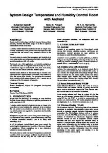
2. System Overview The system adopts the microLogix produced by Rockwell Automation as control unit, which is integrated two analog input and one analog output. It is a cost-effective controller. With the analog input and output port, the device could fulfill the closed-loop process control system. In the automatical system, the thermal resistance PT100 is used as temperature detector and the phase shift regulating thyristor module is used as executive device to adjust the voltage heating device in the oven. The weak voltage signal of thermal resistance is transformed into 4~20mA current signal by the specific converter, then it is connected to the micrologix analog input port. The thyristor module is used to adjust the AC 220 voltage power with the 0~5V voltage signal, so the analog output port must be configure as 0 to 5V. The other digital ports are settled some other logic control component [9, 10]. The system architecture is shown in Figure 1.
Received January 18, 2013; Revised May 19, 2013; Accepted May 29, 2013
4652
e-ISSN: 2087-278X
Figure 1. Block Diagram of the System
3. Control Algorithm First-order inertial lag model is the common mathematical model of the oven as a control object. On this basis, we could use step pulse experiment method more than once to heat the oven at a constant AC 220 voltage. In the same time, we refer to some data from some paper [1-4] [7]. Eventually, the mathematical model of the oven is established, which is shown in Equation 1. 4 .5 t
G (s)
2 .4 9 e 1 1 .7 s 1
(1)
Kp = 2.49, T1 = 11.7 min, τ = 4.5 min From the model, the oven is a large time delay system, the conventional design methods is not suitable for it. Therefore, the dahlin algorithm is adapt to design the controller. The goal of the dahlin algorithm is the desired transfer function of the entire closed-loop system is equivalent to a phase delay links and an inertial link series. Thus the large lag element do not changed but postpone [4]. The closed-loop system presents inertia link characteristics as the Equation 2.
'(s)
2 . 49 0 .7 s 1
(2)
Accordingly, the overall closed loop transfer function of the entire system can be calculated as shown in Equation 3. 4 .5 t
2 .4 9 e (s) 0 .7 s 1
(3)
Therefore, the sampling time is set to 0.5 min. The sample holder is a zero-order hold. Using the pulse function approximation method to design one digital controller, we could use the following matlab procedure to calculate the controller algorithm [4]. gs=tf([2.49], [11.7,1],'inputdelay',4.5) sys=tf([2.49],[0.7,1],'inputdelay',4.5); ts=0.5; gz=c2d(gs,ts,'zoh'); sysz=c2d(sys,ts,'zoh'); gcz=1/gz*sysz/(1-sysz); [n1,d1]=tfdata(gcz,'v') From the result of the above program execution, the z transfer function of the controller algorithm is got, which is the dahlin algorithm shown as the Equation 5.
TELKOMNIKA Vol. 11, No. 8, August 2013: 4651 – 4655
e-ISSN: 2087-278X
TELKOMNIKA
D( z )
4653
U ( z ) n1( z ) E ( z ) d1( z )
1.271z 12 1.8401z 11 0.5962 z 10 0.1024 z 12 0.102 z 11 0.025 z 10 0.1324 z 1 0.0648
(4)
It is known that if the control object already determined, through some calculation, obtain corresponding coefficient, the corresponding difference equation will be obtained. By the above calculation, the z transfer function is got and transformed into the difference equation [4, 7]. the equation is show as Equation 5.
u ( k ) 2 .0432 u ( k 1) 0.3858 u ( k 10 ) 1.5741 u ( k 11) 1.5802 u ( k 12 ) 9 .2006 e ( k 10 ) 28 .3966 e ( k 11) 19 .6142 e ( k 12 )
(5)
From the equation, the key of the dahlin algorithm is to calculate the control variable and error variable, which has been formed in more than one sampling moment ago. So, while the equation in the contoller is calculating, the data of which should be stored and updated. Finally, in ensuring sufficient storage space and calculation accuracy, the PLC can calculate the dahlin algorithm for the temperature control of the oven. There is enough memory space in the Micrologix. The PLC can meet the above requirements for the the dahlin algorithm. As long as we update the corresponding parameters before the end of the PLC scan cycle, the dahlin algorithm can be achieve.
4. Program Design According to the above, if the coefficient has been determined, the difference equation is determined. The ladder diagram of the algorithm controller can be programmed. The flow chart of the main program is listed below Figure 2. Its major porpuse is to complete the following tasks [5]: 1) According to the lag characteristics of the system, some data memory for the calculation should be reserved, which is decided by the control object and its controller. In this case, the D(z) highest time power to 12, the storage space of the difference equation variable should maintain at least 24 word storage space. Therefore, the N7 data storage area in the micrologix is arranged for the data [9]. 2) The PLC should initialize other hardware and software at first scan time, such as analog input, factor. 3) Temperature control has a long control sampling period. To save time, the system use the instructor TON to call the subroutine, which calculates the temperature control input/output data and refresh its memory [11, 12]. 4) Most of the time PLC execute other control process. At last, the subroutine flow chart of dahlin algorithma is shown in Figure 3. This subroutine is scanned every 30 seconds. It will complete the following steps in turn: 1) The value of the analog input port will be read in the spcific storage area and be compute with the settings. the result store in the e(k) storage area. 2) The output value u(k) could compute by using Equation 5. The variable, for example, a, b, c, etc. u(k-1), u(k-11), e(k-1), etc. has been store in the spcific storage area. 3) After computed value of u(k), we should output it to the analog output port. 4) At the end of the subroutine, the value in the variable storage space of the difference equation must to update for the next computing.
5. Simulation and Verification To validate the effect of the dahlin algorithm of temperature control, we use the simulink to simulate it. The simulation diagram is shown in Figure 4. The upper of the diagram is the old system without the dahlin algorithm, the lower of the diagram is the new syetem which is cascaded the dahlin algorithm controller [6]. The distinction of the two system will be calculate and find. Design of the Temperature Control System with the MicroLogix (Sui Tao)
4654
e-ISSN: 2087-278X
Figure 3. Flow Chart of Subroutine of Dahlin Algorithm
Figure 2. Flow Chart of the Main Program
2.5
2.49 2
11.7s+1
1.5
num(z)
2.49
den(z)
11.7s+1
out
1
0.5
time 0
Figure 4. System Simulation Diagram
0
10
20
30
40
50
60
70
80
90
100
Figure 5. Step Response Diagram
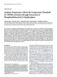
The result of the simulation is shown in the Figure 5, the dash line is the step response curve of the original system, the real line is the step response curve of last system what is cascaded Dahlin algorithm controller. As can be seen from the graph the original system it self is a stable system, but the performance indicators are not very good, such as the rising of temperature is slow. When the system is added the Dahlin algorithm controller, its corresponding speed greatly increased, and overshoot is not too big. So, the design satisfy certain requirements.
6. Conclusion The design is achieve the temperature control system with the Micrologix. For no using the specific moudle, the system is cost-effective. It can be extended to other manufacturers of small PLC applications, such as siemens s7-200 series PLC [1]. But because of the limitation of the dahlin algorithm, the oven model has certain accuracy requirements. If the changes in working conditions, the specfic dahlin algorithm might need some fine tuning. Otherwise, it might cause damage to oven to some extent. So, the using of the dahlin algorithm must be in a cautious way. In some case, if the system working conditions is the same, through adjusting more appropriate parameters, we can realize more accurate temperature control, saving the cost of the production.
TELKOMNIKA Vol. 11, No. 8, August 2013: 4651 – 4655
TELKOMNIKA
e-ISSN: 2087-278X
4655
References [1] Yang Jizhi, Guo Jing. Dahlin Algorithm Based on PLC in Tobacco Ordering Cylinder's Control. Industrial Control Computer. 2011; 24(9): 39-40. [2] Zhang Yu-chi. Temperature Control Algorithm and Simulation Study for an Electric Heating Furnace Based on Single-chip Mircrocomputer. Instrumentation Technology, 2012; 1: 20-24. [3] Yang Linjuan Li Qiuming Gu Deying. Dahlin Algorithm Application in a Temperature Control System. Chinese Journal of Scientific Instrument. 2005; 25(8s): 450-451,454. [4] Zheng Jianxiang. A method of modeling for first-order inertia delay system. Journal of Fuzhou University (Natural Science). 2007; 35(1): 64-69. [5] Hendra Setiawan, Yuhei Nagao, Masayuki Kurosaki, Hiroshi Ochi. IEEE 802.11n Physical Layer Implementation on Field Programmable Gate Array. TELKOMNIKA. 2011; 10(1): 67-74. [6] Doaa M Atia, Faten H Fahmy, Ninet M Ahmed, Hassen T Dorrah. A New Control and Design of PEM Fuel Cell Powered Air Diffused Aeration System. TELKOMNIKA. 2012; 10(2): 291-302. [7] Liao jiao, Liu junfeng, Hu Endian. Design and Simulation of the Digital Controller Based on the Dahlin Algorithm. Ningxia Engineering Technology. 2009; 8(2): 13-15. [8] Alimuddin, Kudang Boro Seminar, Dewa Made Subrata, Nakao Nomura, Sumiati. Temperature Control System in Closed House for Broilers Based on ANFIS, TELKOMNIKA. 2012; 10(1): 75-82. [9] Allen-Bradley. MicroLogix 1000 Programmable Controllers User Manual, Rockwell Automation. 1998. [10] Allen-Bradley. MicroLogix Programmable Controllers Selection Guide, Rockwell Automation. 2011. [11] Qian Xiaolong, MicroLogix controller application example, Beijing, China Machine Press. 2003. [12] Qian Xiaolong, Li Hongru. Intelligent electrical and MicroLogix controller. Beijing: China Machine Press. 2005.
Design of the Temperature Control System with the MicroLogix (Sui Tao)