642
IEEE TRANSACTIONS ON CIRCUITS AND SYSTEMS FOR VIDEO TECHNOLOGY, VOL. 11, NO. 5, MAY 2001
Transactions Letters________________________________________________________________ Design of Wavelet-Based Image Codec in Memory-Constrained Environment Yiliang Bao and C.-C. Jay Kuo
Abstract—This work presents a high-performance wavelet transform based image coder that is designed for image compression in a system with limited resources. In this image coder, the dual-sliding wavelet transform (DSWT) is first applied to image data to generate wavelet coefficients in fixed-size blocks. Here, a block consists of wavelet coefficients only from a single subband. Then, the resulting coefficient blocks are directly coded with the Low-Complexity Binary Description (LCBiD) coefficient coding algorithm. No parent-child relationship is exploited in the coding process. There is no intermediate buffering needed between DSWT and LCBiD. The compressed bit stream generated by the proposed coder is both SNR and resolution scalable, as well as highly resilient to transmission errors. Both DSWT and LCBiD process the data in blocks whose size is independent of the size of the input image. This gives more flexibility in its implementation. The codec has a very good coding performance even the size of a coefficient block is as small as (16,16). Index Terms—Block-based coding, block-based transform, image compression, low complexity compression, wavelet transform.
I. INTRODUCTION
I
MAGE compression based on the discrete wavelet transform (DWT) has been an active research area in last several years. DWT decomposes an image by using wavelets as basis functions [1]. Since this scheme is very efficient in compacting the energy for most images of interest, an image codec of high coding efficiency can be designed accordingly. This idea has been supported by previous work in the literatures, including the work of Shapiro [2], Taubman and Zakhor [3], Said and Pearlman [4], and Xiong, Ramchandran, and Orchard [5], among many others. In addition to coding efficiency, DWT-based image codec is often designed to have SNR scalability by encoding wavelet coefficients in bit planes, or other layered structures. The wavelet decomposition structure also enables resolution scalability in the bit stream. Compared to the current image compression standard JPEG [6], this new technique has higher coding efficiency and richer features achievable with a single bit stream. However, most wavelet image coders proposed so far are inferior to JPEG in the implementational complexity. At the initial Manuscript received September 17, 1999; revised October 3, 2000. This paper was recommended by Associate Editor Z. Xiong. Y. Bao was with the Integrated Multimedia Systems Center and the Department of Electrical Engineering-Systems, University of Southern California, Los Angeles, CA 90089-2564 USA. He is now with Conexant Systems, Inc., Newport Beach, CA 92660–3095 USA (e-mail:
[email protected]). C.-C. J. Kuo is with the Integrated Multimedia Systems Center and the Department of Electrical Engineering-Systems, University of Southern California, Los Angeles, CA 90089-2564 USA (e-mail:
[email protected]). Publisher Item Identifier S 1051-8215(01)03819-8.
Fig. 1. Constrained system for the implementation of image compression algorithms.
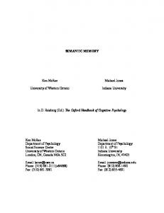
stage of wavelet-compression research, the emphasis was primarily put on the coding efficiency and bit-stream features. It used to be taken for granted that the full picture could be processed as a whole. Such an assumption will certainly limit an effective application of this technology to large images required in real world applications. Ideally, both the wavelet transform and the coding of wavelet coefficients should be performed locally in order to reduce the resource requirements as well as the processing time, while the features provided by the wavelet compression technology should not be sacrificed. Resources are limited in a practical environment in which a compression algorithm is implemented. A memory-constrained environment can be modeled with a diagram as illustrated in Fig. 1. The overall system has a processing unit and a hierarchical memory structure. Here, without loss of generality, we take a two-level memory structure as an example. Buffer is large and inexpensive, but its access delay and data transfer is much faster than but delay are relatively long. Buffer of higher unit cost, and its size is often very limited. This model applies well to the hardware implementation of a compression algorithm at a coarse level. It is desirable to have an algorithm of low memory requirement to reduce the cost. The resource constraint is usually not so strict in software implementation, yet this issue should be considered seriously when a large image is compressed. One of the first set of JPEG2000 test images is of size (14,565, 14 680). During the JPEG2000 competition phase in the summer of 1997, almost all participants compressed this image by partitioning it into smaller tiles. In compressing this and correspond, respectively, to the hard image, buffers disk and the main memory of the computer according to the model given in Fig. 1. In this research, we propose a block-based wavelet image codec that has an extremely low implementational complexity, yet provides very rich features. Here, a block refers to a rectangular area in a single subband, i.e., it is defined in the wavelet domain instead of the image domain. The block size is fixed with possible exceptions when a block meets the subband boundary. No blocking artifacts are introduced in compressed images at
1051–8215/01$10.00 ©2001 IEEE
IEEE TRANSACTIONS ON CIRCUITS AND SYSTEMS FOR VIDEO TECHNOLOGY, VOL. 11, NO. 5, MAY 2001
643
Fig. 2. Boundary overlapping in the block-based wavelet transform.
low bit-rates. It also results in higher flexibility in the codec implementation to process data in blocks whose size is independent of the size of the original image. The codec contains a block-based transform scheme called the dual-sliding wavelet transform (DSWT), as well as a block-based quantization and coding module called the low-complexity binary description (LCBiD) coder. II. REVIEW OF RELATED WORK The Scalable Binary Description (S-BiD) coding algorithm was studied and reported by authors in [7]. It adopted an external wavelet transform scheme and a coefficient coding algorithm that encodes wavelet coefficients in the unit of the tree block.1 It was demonstrated that a wavelet codec could have very high coding efficiency, even if the localized coding was applied on wavelet coefficients. However, no consideration was given to other features of the compressed file in [7]. Besides, the memory requirement of S-BiD is still high in terms of memory size and memory bandwidth. A line-based transform scheme was proposed by Chrysafis and Ortega [8]. In this scheme, the horizontal transform is performed on the entire line. A vertical sliding window is needed to keep enough lines for performing the vertical filtering. One more sliding window is needed for each additional transform step. The widths of all these sliding windows are dependent on the image width. This can be a significant limitation on the application of line-based transform on compression of large-size images. The spatially segmented wavelet transform (SSWT) was proposed in [14]. SSWT attempts to generate wavelet coefficients of all transform levels for each image block fetched. Although quality degradation and compression artifacts can be reduced by using overlapping blocks, both the memory usage and the number of arithmetic operations in the transform will increase because of boundary overlapping. When the line-transform or SSWT is combined with a block-based coder, an intermediate buffer is needed between the transform and the coding stage since transform coefficients are not generated in fixed-size blocks. A block-based coefficient coding scheme called the embedded block coding with optimized truncation (EBCOT) was 1A tree block contains wavelet coefficients from all subbands that are originated from the same location in the original image.
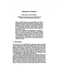
recently developed by Taubman [11] and adopted as the core of the JPEG2000 Verification Model. EBCOT encodes each coefficient block independently. After all blocks are encoded, the final bit stream is formed by concatenating truncated block bit streams and optimized in the rate-distortion performance. EBCOT has high coding efficiency as well as nice features such as smooth SNR scalability. A larger block size 2 has to be used in EBCOT in order to achieve a good coding performance. In addition, the high complexity of the coding procedure, as well as the complexity of bit-stream structure may have a negative impact on its practical applications. III. DSWT In this section, we will present a block-based implementation of the wavelet transform DSWT. DSWT produces wavelet coefficients in blocks. These coefficients are exactly the same as those generated by the normal global wavelet transform. However, the resources required of performing DSWT are significantly lower than that of global transform. Proper handling of overlapping boundaries is the major issue in the design of a localized wavelet transform engine. When the transform is performed on an image block, the block being transformed generally has boundary overlapping with its all four neighboring image blocks as illustrated in Fig. 2. Here, a “boundary” region usually contains several rows or columns of image data. Based on the model presented in Fig. 1, data being . This portion in transformed should be stored in fast memory is referred to as the transform buffer (TB) in this paper. Other . Let us assume that image data may be kept in bulk memory blocks are transformed in a left-to-right then top- down fashion. is transformed, the block above , When block , must have been transand the block at the left side is at the boundaries. If the right vertical formed unless was left in TB, and the bottom horizontal boundary of was stored in some buffer that can boundary of block be easily accessed, all boundaries needed for transforming block are ready, and can be transformed to generate the same results as those from global transform. To avoid the increase in memory requirements due to overlapping boundaries, all transform steps should be separated. The generates four coeffitransform of each image block cient blocks. If pyramid transform is taken as an example, three 2A
typical block size is (64,64).
644
Fig. 3.
IEEE TRANSACTIONS ON CIRCUITS AND SYSTEMS FOR VIDEO TECHNOLOGY, VOL. 11, NO. 5, MAY 2001
Block diagram of the DSWT forward transform.
blocks that belong to LH, HL, HH subbands can be sent to the encoder directly. The LL coefficient block will also be sent directly to the encoder if it is already at the root level, otherwise, the LL subband will be treated just as a smaller image. A. Design of DSWT Engine A DSWT engine of several transform steps basically contains a sequence of cascaded Transform objects. Fig. 3 gives the diagram of a forward DSWT engine for two-step forward wavelet transform. Each transform object corresponds to one step of wavelet transform. A transform object has three buffers: image buffer (IB), transform buffer (TB), and overlapping buffer (OB). The original image is first sent in lines to the Image Buffer in , the first TO, IB1. To generate coefficient blocks of size lines have the first TO will be activated after at least and will be used in the discussion been stored in IB1. to represent the lengths of boundary extension at two ends. Thus, , and its width is equal the height of IB1 needs to be to width of the original image. The LL coefficient blocks will be sent to the corresponding IB in the TO of the next step, if this LL subband will be transformed for an additional step. Data of LL . Thus, subbands are always generated in blocks of size for other transform steps, the transform of the first block row can , which is the minimum number larger be started only after , lines have been stored in the corresponding than , and the width is equal to IB. The height of other IBs is that of the corresponding LL subband. TB is the place where all transform operations, such as boundary extensions and convolutions, are performed. Physically only one TB is needed at any time. Multiple TBs are used in Fig. 3 to have a clearer data flow in the block diagram. The size of , as defined as follows: TB for forward DSWT is (1) (2) The OB is the space that stores horizontal overlapping boundaries. The bottom overlapping boundary of block in Fig. 2 is stored in OB after the block is transformed, and will
be read back to the transform buffer for transforming block . The size of an image block to be fetched and its position in TB depend on whether it is a boundary block or not. The appropriate boundary extension is needed for boundary blocks. Fig. 4 describes how DSWT is performed, especially how the overlapping boundaries are handled, on different image blocks in one step of forward DSWT. In this figure, each square is the transform buffer at a particular state. The tilted-line pattern represents image data. The grid pattern represents wavelet coefficients after both horizontal and vertical transform. The verticalline pattern represents wavelet coefficients after only horizontal transform. The basic requirement in forware transform is that the transform of an image block should always generate four unless the image cannot coefficient blocks of size be partitioned into an integer number of blocks. To minimize memory access operations, a coefficient is written back to TB immediately after it is generated. A certain distance is maintained between the location the coefficient is written to and the location where transform is performed in order to not overwrite any data that will be used in generating other coefficients. High- and low-frequency coefficients obtained after wavelet transform are interleaved. The grid patterns shown in Fig. 4 are used to represent these interleaved coefficients. Vertical overlapping boundaries need to be shifted from the right side of the transform buffer to the left side for performing transform on the next block. The row transform has been performed on horizontal overlapping boundaries before they are written to the OB. Only the column transform will be performed on them after they are read back to TB. Thus, the total number of convolution operation does not increase. We have, so far, discussed the implementation of forward transform. It is trivial to show that the inverse wavelet transform can be performed in a way similar to the forward transform. In inverse DSWT, a TO gets LH, HL, and HH blocks directly from the block coder, and pulls an LL block from the TO of the next level. The TO of the last transform step gets an LL block directly from the block coder. After all four coefficient blocks are
IEEE TRANSACTIONS ON CIRCUITS AND SYSTEMS FOR VIDEO TECHNOLOGY, VOL. 11, NO. 5, MAY 2001
(a)
(b)
645
(c)
Fig. 4. Implementation details of forward DSWT. (a) First block column. (b) Normal block column. (c) Last block column.
available, coefficients are interleaved. Two synthesis filters can be reorganized to form two interleaved filters which are used in performing convolution on interleaved wavelet coefficients to reconstruct the original signal. There is a subtle difference between forward and inverse DSWT. The constraint on forward DSWT is that the coefficient blocks, the output of a TO, must be of fixed size except at subband boundaries, while a TO in inverse DSWT has to accept the fixed-size coefficient blocks as the input. It is in inverse DSWT, convenient to have a TB of size as given in (3) and (4) (3) (4)
B. Discussion On Memory Requirements Three types of buffers (TB, OB, and IB) are involved in DSWT. Based on the above discussion, we would like to summarize their size requirements below. All TOs share the same physical TB. The size of TB is in forward DSWT and in inverse DSWT. If the 9/7 filters are used, the TB’s size is and in forward and inverse DSWT, respectively. If the size of a coefficient block to be generated is of size (16, 16), the size of the TB will be 1600 and 1936 words in the forward and inverse DSWT, respectively, by assuming each coefficient is stored as one word. This size is not dependent on image size.
646
Fig. 5.
IEEE TRANSACTIONS ON CIRCUITS AND SYSTEMS FOR VIDEO TECHNOLOGY, VOL. 11, NO. 5, MAY 2001
Generation of the block-significance bit stream in block skipping. TABLE I TEST OF BLOCK SKIPPING ON JPEG2000 VM2.1
The size of an OB is , where is the is the width of an width of the original image and for . LL subband with the relation The extra point is always given to the low frequency band if is odd. The total space needed by all OBs is bounded by . This is less than if the 9/7 filters are used. A simple memory access unit can be used to perform the reading and writing of overlapping boundaries to and from OBs. The row transform has been performed on data stored in OBs. Thus, the operation of reading overlapping boundaries from OB can be done while the row transform is performed on the block, and the operation of writing overlapping boundaries back to OB can be performed when the column transform is performed. The overhead of transferring overlapping boundaries can be minimized. . The size of other IBs is The size of IB1 is . The total space needed by all IBs converges when the number of transform steps to is infinity, so this is the upper limit of the total IB space for a given image. One major advantage of DSWT is its definition of buffering space hierarchy. The TB is most frequently accessed. Its size is fairly small and not dependent on the size of image processed. As we have mentioned in Section II, the size of sliding windows in line-based transform are dependent on image width. Without further optimization in memory usage, significant buffering space will be needed if a large image is processed. Although there are no image buffers in line-based transform, an intermediate buffer is needed between the line-based transform and a block coder because the coder expects that the coeffients are available in blocks instead of lines. The size of this , and intermediate buffer space can be as large as could be allocated in a slow memory. On the contrary, DSWT is designed to work with a block-based coder, no such intermediate buffering space and operations are needed. IV. BLOCK-BASED ENTROPY CODING COEFFICIENTS
OF
WAVELET
Wavelet coefficients are usually encoded in bit planes in order to have a bit stream that can be decoded progressively in quality.
A bitplane is further partitioned into three parts composed of significance bits, sign bits, and refinement bits, respectively [2]. One type of bit-plane coding algorithm encodes these bits by using context-based binary arithmetic coding [3], [9]. A subband is encoded in bit planes, and each bit plane of a complete subband is scanned and encoded in the raster order. When a subband is partitioned into blocks, a block is usually of a much smaller size than a subband, and most blocks become significant much later than a subband as illustrated in Fig. 5. The height of a vertical bar represents the maximum coefficient (absolute value) in the block. The position of a dashed arrow indicates the magnitude of the current threshold in bit-plane coding. A block (or subband) is significant if at least one coefficient in the block (or subband) is significant. A separate bit stream is generated to describe the significance of blocks as illustrated in that figure. If a block is insignificant, it is not necessary to scan individual coefficients within the block. Otherwise, the coefficients within the block are scanned in the raster order. A block of zeros can be effectively “skipped” if no coefficients in the block are significant. By introducing this block-skipping scheme, the total number of symbols that need to be encoded is reduced greatly, and both the coding efficiency and coding speed can be increased. The experiment on block skipping is performed in JPEG2000 VM2.1. The original JPEG2000 VM2.1 has the block size of 1, i.e., no block skipping. The modified VM has a two-level scanning structure, and the block size can be defined by users. The introduction of block-skipping results in the increase in both coding efficiency and coding speed. The quality of the compressed file as well as the coding time are obtained at different bit rates and block size for four JPEG2000 test images: aerial2, bike, cafe, and woman. Image aerial2 is of size (2048, 2048). Others are of size (2048, 2560). The numbers listed in Table I are the average results on these four images. The value of coding time is normalized with that of the original VM as 100. The improvement is block size dependent. The increase in PSNR and the coding speed is very obvious. In generating experimental results listed above, it is still assumed that coefficients of the whole image are accessible during
IEEE TRANSACTIONS ON CIRCUITS AND SYSTEMS FOR VIDEO TECHNOLOGY, VOL. 11, NO. 5, MAY 2001
647
(a)
Fig. 6.
Encoding process of LCBiD.
the entire encoding process. What we can learn from these results is that it is beneficial to encode coefficients in blocks. Less zeros are coded by using the block-skipping technique. The corresponding statistical model is also more consistent when a bit plane is scanned in blocks.
(b) Fig. 7. Scanning of coefficients within a block. (a) Normal rastering scanning. (b) Non-interrupting scanning.
A. Low Complexity Binary Description Coding Based on the results obtained in the last section, the LCBiD coding scheme is developed to generate a scalable bit stream by encoding coefficients in blocks. Once a block is fetched into a processing buffer, it is completely encoded. A bit stream that is scalable in both SNR and resolution usually contains a 2-D array of data units, with one dimension indexed by the resolution level and the other indexed by the image quality. If all blocks of all subbands are simply encoded sequentially using a single arithmetic coder, the bit stream can only be decoded in one mode, the inverse of the encoding process. The coding process in LCBiD is illustrated in Fig. 6. A separate arithmetic coder is used for each bit plane of each subband. The arithmetic coder is reset before a subband bit plane is encoded. The statistical information is shared among blocks within the same subband during the entire coding process. The arithmetic coder is flushed after the coding of the subband bit plane is finished. A minimum data unit (MDU) is defined as a compressed data segment that corresponds to a bit plane of a subband. After all data in one MDU have been formed, a bit-stream header is constructed and added to indicate the length of each MDU. When the bit stream is decoded, each MDU can be directly accessed without any extra decoding operations. The scalable decoding means that only a subset of bit stream needs to be decoded in order to reconstruct an image according to certain decoding criterion. The quality scalable decoding of the bit stream can be achieved by decoding the MDUs in the SNR decreasing order. The resolution scalable decoding can be achieved by decoding only these MDUs that belong to the subbands that contribute to the image of the reduced resolution. The compressed file also has a better error-resilient property because bit errors can be isolated since the length of each MDU is known. During the coding of a block, coefficients are usually scanned in the rowwise order as illustrated in Fig. 7. In this figure, (4, 4) coefficient block is used as an example. Note that the statistics of coding symbols varies abruptly from the last line in the previous block to the first line in the current block. If the coefficients are scanned in the columnwise order, this abrupt change can be eliminated. This scanning mode is named as noninterrupting scanning (NIS), which is adopted in generating results reported
Fig. 8. Definition of coding contexts.
in the paper. For all the images tested, NIS always improves the coding efficiency, for as much as 0.08 dB. Considering almost no extra effort is needed, it is worthwhile to implement NIS. The idea of NIS can be applied to other block-based codecs as well. In order to simplify the codec design, LCBiD does not treat subbands differently. All subbands are partitioned and scanned in the same fashion. In block-based coding, zero padding is applied at its boundaries when coding contexts for the coefficients at the boundaries are calculated. The correlation among wavelet coefficients that are separated by block boundaries can no longer be exploited. This results in coding efficiency degradation which could otherwise be avoided in a global coding scheme. This type of correlation can be partly recovered by using a single overlapping column. After a block is encoded, the right-most column of the block is left in the cache. When the next block in the same block row is coded, this column participates in the calculation of coding contexts, but is not coded twice. It is necessary to have a simple definition of coding contexts in order to reduce the total number of statistical models and the implementational complexity. In generating results of LCBiD reported in this work, only 13 coding contexts are used in each arithmetic coder. The definition of coding context is the same for all subbands. Among these 13 contexts, eight coding contexts are used for coding of the coefficient significance information. Eight coding contexts are represented as a 3-bit number, and formed with the significance bits of six immediate neighboring coefficients. The formation of these 3 bits are explained or is the significance or sign bit of coefin Fig. 8. . or can be either 0 or 1. Two coefficients ficient that do not contribute to the significance bit context calculation
648
IEEE TRANSACTIONS ON CIRCUITS AND SYSTEMS FOR VIDEO TECHNOLOGY, VOL. 11, NO. 5, MAY 2001
Fig. 9. Data flow in a block-based image codec.
are labeled with gray numbers in the figure. The contexts for coding a sign bit are formed with the significance bit and the sign bit of the previous coefficient. This is the coefficient above the coefficient currently being coded when NIS is applied. Its mathematical definition is also given in Fig. 8. The refinement bit stream is encoded in a single coding context. The bit stream that tells when the blocks become significant are also coded in a separate coding context. B. Complexity Analysis Buffers are needed in LCBiD to store coefficients and coding contexts. A separate arithmetic coder is needed for generating each MDU. A considerable amount of space will be needed to store the statistical models. The state variables of the arithmetic coder and the output buffers of the arithmetic coder will also consume some amount of memory. However, they are not considered here since this part can depend on the specific implementation. It is easy to get a rough complexity analysis of LCBiD with the following reasoning. There are only 256 coefficients in a block. As explained earlier, one line of the overlapping boundary is kept in the memory after one block is coded. Thus, if a coefficient is stored as a 16-bit number, the size of the coefficient buffer is bytes. The significance bit-coding context and the sign bitcoding context of each coefficient are combined to form a single number that can be stored as 1 byte. The size of the context buffer is 272 bytes, including a state map for the single-column overlapping boundary. Here, it is assumed arithmetic coders of accurate symbol counting and re-normalization are used [15]. The memory requirement can be analyzed similarly if the arithmetic coder of another type is used. Thirteen statistical models are maintained for each arithmetic coder. A statistical model in binary adaptive arithmetic coding contains the count of symbol 0’s and 1’s that have been coded. It is normally sufficient to store a complete model with 2 bytes. If the minimum quantization step size is , the number of bit planes that will be coded in a subband at transform step will be no more than
(5)
The total number of MDUs, under the assumption that the number of transform steps is , is upper bounded by
(6) If the number of transform steps is five and the minimum quantization step size is eight, the total number of MDUs is 130. The states of 130 arithmetic coders are maintained during the entire coding process. Not all arithmetic coders are active at a time. Once a TO of a certain step is active, a complete block row of the original image or an LL subband is transformed and coefficients of four subbands are generated. Except for the last transform step, only coefficients of three subbands need to be coded. Thus, it is only necessary to maintain three sets (or four sets for the last transform step) of arithmetic coders and related statistical models corresponding to a transform step. All other parameters can be swapped to a secondary storage device. Since only certain state variables of the arithmetic coders are stored, the space needed for storing this information is fairly small. More details on the state variables can be found in [15]. V. INTEGRATION OF DSWT AND LCBID A low complexity wavelet image codec is designed by integrating DSWT and LCBiD. DSWT perfectly matches LCBiD in that wavelet coefficients are generated in blocks, and these blocks can be directly encoded by LCBiD. The intermediate buffer is not needed. The integrated system is described below. An image is sent to the transform engine in lines. The coefficient blocks generated by DSWT are sent to a deadzone quantizer. Deadzone quantization is applied only to individual coefficients, so that the quantization can be performed on the fly while a coefficient block is formed. The quantization step size is specified by the user. For many applications, direct control of image quality is of more interest to the user. For rate-critical applications, the target bit rate can be achieved by adjusting the quantization step iteratively or truncating the scalable compressed bit stream. Fig. 9 depicts the buffer allocation and the data flow in the block-based image codec. The compressed bit planes of all subbands are separately generated. The final bit stream can be
IEEE TRANSACTIONS ON CIRCUITS AND SYSTEMS FOR VIDEO TECHNOLOGY, VOL. 11, NO. 5, MAY 2001
649
TABLE II CODING PERFORMANCE OF THE PROPOSED BLOCK-BASED WAVELET CODEC
TABLE III LENGTH OF COMPRESSED BIT PLANES IN EACH SUBBAND (LENA, 512
formed by simply concatenating these data units. The LCBiD coder encodes/decodes coefficients in blocks of size (16, 16). The memory usage of the transform engine can be calculated according to the complexity analysis in Section III-B and Section IV-B. VI. CODING EFFICIENCY OF THE PROPOSED CODEC Even though our image codec design has been constrained by a severe memory requirement, the coding performance of the proposed codec is still among the best in all known image codecs as demonstrated by experimental results given in this section. The proposed block-based image codec was applied to four JPEG2000 test images: aerial2, bike, cafe and woman. Its results and those of JPEG2000 VM3.0A and SPIHT [4] are listed in Table II. Note that even though JPEG2000 VM4.0 is available now, the kernel coding algorithms of VM4.0 and VM3.0A are essentially the same, i.e., EBCOT. The coding performance of
2 512)
VM4.0 is however lower than VM3.0A because more bit stream features are added. Two separate sets of experimental results are generated with VM3.0A. Results “VM3.0A-32” are generated by running the VM3.0A encoder with a coding block size of , while results “VM3.0A-64” are with block size of . Both sets of data are generated with the “SNR-progressive” flag turned on. SPIHT is not a low complexity codec. It is implemented in the full-frame coding mode. A compressed bit stream generated with SPIHT is not scalable in resolution. In all experiments reported here, the 9/7 biorthogonal filters [13] are used. All images are decomposed with the pyramid transform for all codecs. For VM3.0A and SPIHT, the number of transform steps are determined by the codec. For LCBiD, the number of transform steps is always set to five for all the results in Table II. From these experimental results, we can clearly see that the proposed codec has the best coding efficiency among all three codecs while its memory requirement is the lowest. Although no inter-subband correlation is exploited, LCBiD has
650
IEEE TRANSACTIONS ON CIRCUITS AND SYSTEMS FOR VIDEO TECHNOLOGY, VOL. 11, NO. 5, MAY 2001
better performance than SPIHT. The authors believe that is due to efficient context-based coding of significance and sign bits in LCBiD. Improvement in coding efficiency may be achieved if the inter-subband correlation is also taken into consideration in defining the context models in LCBiD, however, this will introduce the dependency in coding different subbands which should be avoided in order to have more flexibility in implementing the coder. The coding efficiency of the proposed codec can be slightly higher if the block size is larger than 16, because less zero padding is applied at block boundaries. The improvement in the coding efficiency by using blocks of size (64, 64) is between 0–0.06 dB for the four test images used. Since the improvement in coding efficiency is not significant, we prefer to choose the smaller block size (16, 16) due to the memory consideration. Before examining the scalability issue of the compressed bit stream, let us look at the structure of a compressed Lena file of at the bit rate of 2.0 bpp, and the transform step size of 4. The compressed file contains a 139-byte bit-stream header and a 65 391-byte data segment. The header stores the image and compression parameters. It also includes an indexing structure telling the length of each MDU. As explained earlier, an MDU is the part of the compressed bit stream that corresponds to a bit plane of a subband. All MDUs can stored in a data segment in a quality-progressive order, or a resolution-progressive order. The lengths of all MDUs in the example are listed in Table III, and these numbers are stored in the bit stream header. The accumulated data length (denoted by A. bytes) and accumulated bit rate (denoted by A. bit rate) at each bit plane are also listed in the table. In SNR decoding, it is preferred to stop the decoding at the points where all subband bit planes at the same level are bpp is such a decoded. For the example in Table III, preferred truncation point. All preferred truncation points can be easily found by inspecting the bit-stream header. PSNR in Table III is calculated at the preferred truncation points. The decoding can also be stopped at any other point other than these preferred truncation points. Although continuous SNR scalability can be achieved, the rate-distortion curve is not very smooth. The PSNR value climbs slowly when the bit rate increases, and is just above a preferred truncation point. The PSNR increases much faster when the bit rate approaches the next preferred truncation point. The rate-distortion curve can become smoother if the bit stream of bit plane can be arranged so that the bit-stream truncation results in the loss of less important bit stream. This can be achieved by coding significace and refinement bits of each bit plane separately as in the embedded wavelet coder as [2] and [4], or even more layers as in EBCOT [11]. However, the implementational complexity will increase. The degradation in coding efficiency will be more obvious for small images because of an increased amount of data units.
VII. CONCLUSION AND FUTURE WORK A block-based image codec was designed by integrating the block-based transform (DSWT) and block-based coefficient coding (LCBiD). The codec has a very low implementational complexity. The size of cache memory needed is image-size independent. The coding efficiency of the codec was proven to be very high. It outperforms other high-performance wavelet coders in the same class. The bit stream generated with the image codec is scalable in both SNR and resolution. The image codec has a very simple coding process, while the requirement on the local storage is very small, since it is possible to transmit the compressed data as soon as they are generated. The compressed file has a simple structure that can be easily parsed in the decoder. Other work to reduce the implementational complexity of the wavelet image codec is possible. For example, it is desirable to replace all floating point computation to fixed point computation and to replace the multiplication with addition/substraction and bit-shift operation as much as possible. This is out of the scope of this paper, but worth careful study in the design of a special purpose chip for image compression. REFERENCES [1] S. G. Mallat, “A theory for multiresolution signal decomposition: the wavelet representation,” IEEE Trans. Pattern Anal. Machine Intell., vol. 11, pp. 674–693, July 1989. [2] J. M. Shapiro, “Embedded image coding using zerotrees of wavelet coefficients,” IEEE Trans. Signal Processing, vol. 41, pp. 3445–3462, Dec. 1993. [3] D. Taubman and A. Zakhor, “Multirate 3-D subband coding of video,” IEEE Trans. Image Processing, vol. 3, pp. 572–588, Sept. 1994. [4] A. Said and W. A. Pearlman, “A new, fast, and efficient image codec based on set partitioning in hierarchical trees,” IEEE Trans. Circuits Syst.Video Technol., vol. 6, pp. 243–250, June 1996. [5] Z. Xiong, K. Ramchandran, and M. T. Orchard, “Space-frequency quantization for wavelet image coding,” IEEE Trans. Image Processing, vol. 6, pp. 677–693, May 1997. [6] W. P. Pennebaker and J. L. Mitchell, JPEG, Still Image Data Compression Standard. New York: Van Nostrand, 1993. [7] Y. Bao, H. Wang, R. Chung, and C.-C. J. Kuo, “Design of a memoryscalable wavelet-based image codec,” in Proc. IEEE Int. Conf. Image Processing, Chicago, IL, Oct. 4–7, 1998. [8] C. Chrysafis and A. Ortega, “Line-based, reduced memory, wavelet image compression,” in Proc. Data Compression Conf., Snowbird, UT, Mar. 1998. [9] C. Christopoulos, “JPEG-2000 verification model VM version 2.0/2.1,” ISO/IEC JTC1/SC29/WG1 N988. [10] Y. Bao, M. Shen, and C.-C. J. Kuo, “Dual sliding wavelet transform, generating same coefficients in fixed-size blocks,” ISO/IEC JTC1/SC29/WG1 N1217. [11] D. Taubman, “Report on codEff22: EBCOT (embedded block coding with optimized truncation),” ISO/IEC JTC1/SC29/WG1 N1020. [12] Y. Bao and C.-C. J. Kuo, “Low complexity binary description codec,” presented at the IEEE Int. Workshop Multimedia Signal Processing (MMSP’99), Copenhagen, Denmark, Sept. 13–15, 1999. [13] M. Antonini, M. Barlaud, P. Mathieu, and I. Daubechies, “Image coding using wavelet transform,” IEEE Trans. Image Processing, vol. 1, pp. 205–220, Apr. 1992. [14] C. Christopoulos, “JPEG2000 verification model 4.0 (Technical description),” ISO/IEC JTC1/SC29/WG1 N1282. [15] I. H. Witten, R. M. Neal, and J. G. Cleary, “Arithmetic coding for data compression,” Commun. ACM, vol. 30, no. 6, pp. 520–540, June 1987.