Design Optimization and SNR Performance of 3T 96 Channel Phased Array Head Coils. G. C. Wiggins1, V. Alagappan1, A. Potthast2, M. Schmitt1, C. J. ...
Design Optimization and SNR Performance of 3T 96 Channel Phased Array Head Coils G. C. Wiggins1, V. Alagappan1, A. Potthast2, M. Schmitt1, C. J. Wiggins1, H. Fischer2, K. Jahns2, T. Benner1, J. Polimeni1, and L. L. Wald1 1 Radiology, MGH Martinos Center, Charlestown, MA, United States, 2Siemens Medical Solutions, Erlangen, Germany
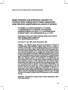
Introduction: As the number of receive array channels (N) increases, theoretical analysis predicts that it is possible to reduce the size of the individual elements and get increasing SNR gains near the elements without losing sensitivity further from the coils, in addition to encoding acceleration performance (1). These theoretical studies are usually performed assuming ideal decoupling between the elements and body load dominant conditions. However, a 90 channel head array that we constructed for 1.5 showed a central SNR which dropped significantly compared to a 23 channel array of similar geometry with fewer, larger coil elements (2). We attributed this to poor loading of the small surface coil elements which could be readily addressed with the increased loading at higher field. In this work we address additional loss mechanisms unique to large-N arrays and the effect of an increased number of coupling partners as N is increased We have evaluated two designs for a 96 channel head array for 3T with particular attention to sources of SNR loss in the small coils, including various sources of coil loading and SNR deterioration due to coupling between coil elements. Our overall goal was for the larger-N array of small coils to gain peripheral SNR and at least equal the central SNR of a 32 channel helmet of similar geometry (3). Design changes aimed at reducing coupling among the channels and reducing losses due to induced eddy currents in the copper of adjacent coil elements were found to be necessary to achieve this goal. The designs were evaluated in phantom and human SNR and imaging measurements Methods: The coil arrays were tested on a modified Tim Trio 32 channel 3T clinical scanner (Siemens Medical Solutions, Erlangen Germany). The system was expanded to 128 channels by the addition of 3 more sets of 32 receivers, fully integrated within the system architecture. The coil elements were critically overlapped to minimize inductive coupling, and arranged on a close-fitting helmet using the soccer-ball element geometry described previously for 1.5T (2). Coil element designs were evaluated for loaded and unloaded Q both alone and within the array. Two types of elements were evaluated, both nearly 5cm diameter: 1) “circuit board elements” constructed from 5mm width G10 copper clad circuit board (1 Oz / ft2) with 6 or 2 capacitors per coil with a standard capacitive match and preamp decoupling implemented through control of the length of coax (37cm) between the coil element and the preamp, and 2) “wire elements” constructed of bent 16awg copper wire, with 2 capacitors per coil, a series match and separate detuning circuit, and a new design of preamp with built in cable trap (Siemens Medical Solutions, Erlangen Germany) attached to the coil with a short (5cm) length of semi rigid coax (Figs 1, 2). SNR comparisons were made using proton density gradient echo images (TR/TE/flip/slice = 200ms/4.07ms/20deg/3mm, 256x256, FoV=220mm) obtained in human scans using the prototype arrays and an in-house 32 channel head coil with identical helmet dimensions (3). Results: The 6-capacitor “circuit board elements” showed a QUL/QL ratio of 280/110=2.5 when comparing the unloaded coil in free space to the coil located 1cm from the head. However, when placed in the array surrounded by the other untuned coil elements, QUL was reduced to 208 due to eddy current losses in the surrounding copper, reducing QUL/QL to 1.9 within the array, a drop of 26%. Reducing the number of capacitors from 6 to 2 was found to increase QUL by 48%. The 2 capacitor “wire elements” had a QUL/QL of 410/110=3.7. When placed in the array surrounded by other wire coil elements QUL was only reduced by 6%, resulting in a final QUL/QL of 3.5 within the array. For the ”circuit board elements”, the match capacitor required for 50 Ohm match was 200pF, resulting in a low Q detuning trap, leading to a weak preamp decoupling (less than -18dB). The use of a series match capacitor in the optimized array allowed for 62pF to be used in the detuning trap, increasing the preamp decoupling to better than -25dB. SNR profiles are shown in Fig. 2. The sum of squares SNR achieved with the “circuit board element” prototype was 40% lower in the center of the head than the 32 channel helmet coil, and only reached higher SNR than the 32 channel coil in selected parts of the outer cortex. The “wire element” with optimized preamp detuning shows essentially the same SNR in the center of the head as the 32 channel coil, and gains of as much as 100% in the cortex. Conclusions: The use of 2 capacitors per element and the use of wire (which reduced losses due to eddy currents) improved the SNR of the optimized array, but the most significant factor affecting the array SNR was reducing coupling through the enhancement of preamp decoupling. In a high-N array there are many next-nearest neighbors for each coil element, which do not benefit from the critical overlap between immediate neighbors. As preamp decoupling weakens, all these coils interact with each other and the SNR rapidly deteriorates. Close attention to minimizing coil losses and maintaining strong preamp decoupling made it possible to extend the close fitting helmet array design to 96 channels at 3T and achieve the theoretical SNR benefits including significant SNR gains in the cortex, in addition to the significant g-factor gains previously observed.
Fig. 1 Detuning and match circuits for the two 96 channel array designs
Fig. 2. Close up of coil elements from two different 96 channel array designs. Left: Circuit board coil elements, Right: Wire coil elements
Fig. 3. SNR Profiles for the 3 coil designs
[1] Wright, SM et.al. NMR Biomed, 1997 10(8) p.394-410 [2] Wiggins GC et. al. Proc ISMRM 2005, p671 [3] Wiggins GC et. al. Mag Reson Med. 56:216-223 (2006)
Proc. Intl. Soc. Mag. Reson. Med. 15 (2007)
243