Design Solutions for Multi-Object Wireless Power ... - Semantic Scholar
Recommend Documents
wireless body area networks and gives an overview of ... The wireless body area network (WBAN) is a ..... low power wireless technologies are required, which.
AbstractâThe wireless power transfer (WPT) efficiency of sys- tems based on ... M. M. Tentzeris is with the Georgia Electronic Design Center, School of Elec-.
Sep 23, 2015 - Fujii, T.; Ishida, S. Cardiac Pacemaker Using Wireless Transmission. ... and optimization of printed spiral coils for efficient transcutaneous.
design problem for simultaneous wireless information and power transfer in ... in energy-constrained wireless networks. In practice ..... Cambridge Univ. Press ...
Wireless; system-on-chip; design; processor; hardware accelerator; power ..... in the IEEE Standard 802.11 is Carrier Sense Multiple Access with Collision.
May 30, 2008 - personal or classroom use is granted without fee provided that copies are not made or distributed for profit or commercial advantage and that ...
Aug 9, 2016 - at. Imperial. College. London, London. SW7. 2AZ, United. Kingdom. (email: ..... strategy. With such a linear model, a single-sine waveform is.
Abstractâ Aiming at the disadvantage of current anti-theft technology, a novel smart grid based wireless power theft monitoring .... well suited for communication gateways and protocol converters, soft ... ADVANTAGES AND LIMITATIONS.
Sep 21, 2015 - The current system is able to provide about 1 W power and is able to recharge ... The endoscopic capsule in which the wireless recharging.
These additional wireless technologies provide a basis for a very rich array of applications, including local telephony service, broadband Internet access and.
Sep 13, 2017 - School of Information, Qilu University of Technology, Jinan 250353, China; ... of Wireless Communication Technologies, Shandong University,.
Mar 16, 2017 - solution to the problem with imperfect channel state information. (CSI) of the ... in [10]. To describe the trade-off between the rates at which ... of Electronic and Electrical Engineering, University College London, United Kingdom. (
different RF load matching circuit. Over the last several years our test lab has developed over a hundred RF test solutions for a wide range of design teams.
Nov 22, 2012 - Wireless charging was first demonstrated by Nicola Tesla at the end of ... Tesla announced that a Tesla tower, a large coil lighting fixture for a ...
Georgia Institute of Technology, 85 5th street NW, Atlanta, GA 30308, USA. Abstract â In ... Index Terms â Wireless power transmission, RF energy harvesting.
small, handheld wireless devices. ... speed, low-power wireless computation opens up exciting ... component, Pleak, is due to gate-oxide tunneling current,.
Md. Mainul Islam Mamun, Tarek Hasan-Al-Mahmud, Sumon Kumar Debnath, Md. Zahidul Islam. ABSTRACTâ There is now an increased understanding of the ...
In this article, we present a system for energy measurement at mains sockets to gain a transparent .... nect 230-V devices to measure grid voltage and electricity.
are no MAC protocols that adapt both rate and power ... ios. There are two typical deployment scenarios for wire- less networks: high bit-rate networks and low ...
May 20, 2005 - Large scale deployments of these networks have been used in many diverse fields such as wildlife habitat monitoring [7], traffic monitoring [1] ...
Wireless link. Access Point. Mobile Host. Fixed Host. Figure 1: Scenario. Experimental results show that, by adopting our PSNA architecture to integrate a ...
signal extraction from a wireless carrier is accomplished using. Schottky barrier ... and constant-voltage loops, and eliminates the external current sense resistor ...
For a constant charging current of 100 µA, an RF power of 2.4. mW needs to be ... desirable to develop a wireless implantable pressure sensor, which can be ...
The wireless technology is becoming one of the most prominent areas of research. ... transceiver standard in Wireless Sensor Networks, a ZigBee technology.
Design Solutions for Multi-Object Wireless Power ... - Semantic Scholar
(2) Multiple Activation Technique of Small TX-. Coils for Position Adjustment-Free WPT. (3) OFET Level-Shifters with Adaptive Biasing. âSummary ...
Design Solutions for Multi-Object Wireless Power Transmission Sheet Based on Plastic Switches M. Takamiya, T. Sekitani, Y. Miyamoto, Y. Noguchi, *H. Kawaguchi, T. Someya and T. Sakurai University of Tokyo *Kobe University
Outline Wireless Power Delivery for Ubiquitous Electronics Wireless Power Transmission Sheet (WPTS) Key Circuit Technologies for WPTS (1) Mixed Circuit of MEMS Switches and Organic FETs with Two Frequencies for Shared Coil (2) Multiple Activation Technique of Small TXCoils for Position Adjustment-Free WPT (3) OFET Level-Shifters with Adaptive Biasing
Power Transmission with Electromagnetic Induction Magnetic fields RX-coil I1 TX-coil
dI1 V2 = M dt
Advantage Wireless power transmission provides the mobility for RX-coil. Drawback Displacement degrades the power transmission efficiency. 4
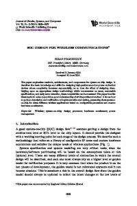
Power Transmission Efficiency Loss 1 large TX-coil
Many small TX-coils
RX-coil 1 inch2 TX-coil
30cm2 X 1 coil Efficiency ~ 0.1%
RX TX
1 inch2 X 64 coils Efficiency ~ 60%
Segmentation and selective activation of TX-coils prevent the efficiency loss. Position detection of the RX-coil is required. 5
Position Detection of RX-Coil w/o RX-coil with RX-coil
TX-coil
TX voltage
RX-coil
Frequency Scan TX-coils and monitor the TX voltage change at a given frequency.
6
Outline Wireless Power Delivery for Ubiquitous Electronics Wireless Power Transmission Sheet (WPTS) Key Circuit Technologies for WPTS (1) Mixed Circuit of MEMS Switches and Organic FETs with Two Frequencies for Shared Coil (2) Multiple Activation Technique of Small TXCoils for Position Adjustment-Free WPT (3) OFET Level-Shifters with Adaptive Biasing
Summary 7
Device Structures of WPTS TX-coil array
21 cm
Printable MEMS switches for power transmission Organic FETs (OFETs) for RX position detection
21 cm RX-coil
Printable switches provide the low cost solution for the largearea applications 8 x 8 array (1-inch pitch) such as WPTS. Switch Speed On-resistance MEMS ~ 1Hz < 10Ω Complementary OFETs > 100Hz > 1kΩ
8
Wireless Power Transmission Sheet
21 cm
OFETs MEMS switches Embedded in the floor
8 x 8 TX-coil array
9
Power Transmission to LEDs
TX RX
RX-coil 13.56 MHz 38 LEDs
TX-coil array
m m 4 . 5 2
(Without OFETs)
5-mm distance between RXand TX-coils 10
Power Transmission to LEDs
11
Plastic MEMS switches
10 mm x 20 mm, 4 Hz (max) 12
Outline Wireless Power Delivery for Ubiquitous Electronics Wireless Power Transmission Sheet (WPTS) Key Circuit Technologies for WPTS (1) Mixed Circuit of MEMS Switches and Organic FETs with Two Frequencies for Shared Coil (2) Multiple Activation Technique of Small TXCoils for Position Adjustment-Free WPT (3) OFET Level-Shifters with Adaptive Biasing
Summary 13
Shared Coil Sheet Previous work [1]
This work TX-coil array
Coil for PT MEMS
MEMS switches for power transmission (PT) OFETs for RX position detection (PD)
Coil for PD
OFET
[1] T. Sekitani, et al., IEDM2006.
Shared coil sheet reduces the fabrication cost and increases the position detection efficiency. 14
Mixed Circuits of MEMS and OFETs for Shared Coil Unit circuits for 8 x 8 array f1 =3.5 MHz for position detection
TX
RX
MEMS switch + On
CP 13.56 MHz for power transmission
0V C1 to distinguish 2 frequencies
VMON
Off
Monitor for PD
Mixed circuits of MEMS switches and OFETs with two different frequencies enabled the shared coil. 15
Frequency for Position Detection Measured
6 Without RX-coil
VMON (V)
5 4 3
Maximum frequency for OFETs
With RX-coil
2 1 0 0
3.5 5 10 Frequency (f1) (MHz)
15
3.5 MHz was used due to the speed limitation of OFETs. 16
Position Detection with Shared Coil Measured
Without RX-coil With RX-coil
0.3 f1 = 3.5 MHz
VMON (V)
0.2 0.1 0
ab
b-a = 33% b
-0.1 -0.2 -0.3 0
250 500 750 1000 1250 Time (ns)
33% voltage change is acceptable for the position detection, while 91% was achieved with separate coils [1].
17
Outline Wireless Power Delivery for Ubiquitous Electronics Wireless Power Transmission Sheet (WPTS) Key Circuit Technologies for WPTS (1) Mixed Circuit of MEMS Switches and Organic FETs with Two Frequencies for Shared Coil (2) Multiple Activation Technique of Small TXCoils for Position Adjustment-Free WPT (3) OFET Level-Shifters with Adaptive Biasing
Summary 18
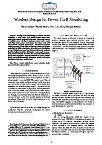
Previous work [1] TX RX Spectrum analyzer 200 mW 100μm distance TX RX y
Power efficiency (%)
Exact Position Adjustment was Required
TX-coil pitch = 1 unit = 25.4 mm
60 50 Next TX-coil should be selected
40 30 20 10 0
0
0.2 0.4 0.6 0.8 Displacement (y) (unit)
1
Displacement of TX/RX coils with the same diameter rapidly reduces the power efficiency. 19
Multiple Activation Technique of Small TX-Coils 4 unit TX RX
TX RX
y
y 1x1
Power efficiency (%)
Ref[1]
TX RX
RX TX
y 2x2
y 3x3
y 4x4
60 50 40 30
Ref 3x3
Conv. Same 2x2 Single
20 10
4x4
1x1 00 0.2 0.4 0.6 0.8 Displacement (y) (unit)
Proposed Different diameter Multiple activation
1 20
Position Adjustment-Free WPT Power efficiency (%)
60 50 Best choice 40 30 max ave. min
20 10 0
0
Ref[1] 1x1 2x2 3x3 4x4 Activated number of TX-coils
3 x 3 coils activation is the best design choice, because the minimum efficiency determines the specification of WPTS. 21
Outline Wireless Power Delivery for Ubiquitous Electronics Wireless Power Transmission Sheet (WPTS) Key Circuit Technologies for WPTS (1) Mixed Circuit of MEMS Switches and Organic FETs with Two Frequencies for Shared Coil (2) Multiple Activation Technique of Small TXCoils for Position Adjustment-Free WPT (3) OFET Level-Shifters with Adaptive Biasing
Summary 22
Why OFET Level Shifters? Wireless power transmission sheet Silicon VLSI for controller
MEMS OFETs
VDD = 1V ~ 5V
VDD = 40V ~ 100V
Level shifters
Costs
High voltage tolerant silicon IC OFETs
High Low
Design target: OFET level-shifters from 5 V to 40 V 23
OFET Level Shifters pMOS-only design In
5V 0V
SF
SF
SF
Out
40 V 0V
40 V
40 V
In
Vadap
Out Out
In
Gain = 2.6 Bias
Source follower Single amp Adaptive biasing is required to deal with PVT variations.
24
OFET Level Shifters with Adaptive Biasing SF
In
SF
SF
+
Original
20 V Vadap
+
Vadap
SF -
SF
-
Replica 2.5 V
SF
20 V Out
Out
40 V
20 V 5V 2.5 V 0V
In
Adaptive biasing requires high gain diff. amp.
25
3 Differential Amps with Different Loads Enhancement
& Depletion
pMOS with back gate The gain of three amplifiers are compared at fixed power. Identical 40 V
In Out
Inb Outb
Diode-connected load
In
Inb
Out
Outb
-30V
-30V
Triode load
In Out
Inb Outb
Current-source load (proposed)
26
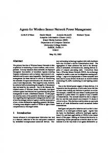
Gain Comparison of Differential Amps
Inb, Out, Outb (V)
40
G: Gain @ In=20 V
Simulated Out
Outb
CS load (G = 15)
30
Triode load (G = 4.5)
20
Diode load (G = 0.6)
10 Inb 0
0
10
20 In (V)
30
40
Current-source load achieved the highest gain.
27
Output Impedance(rO) of Driver and Each Load Diode load Out (rO = 0.20MΩ)
12
-30V
ID
10 ID (μA)
rO @ In=20 V
Simulated
14
ID
Triode load (rO = 1.9MΩ) Out
8 1/rO
6
ID
4
CS load (rO = 11MΩ)
2 0
Out
VP
20V
0
10
20 Out (V)
30
The high gain derived from the large rO.
40
ID
Driver Out (rO = -10MΩ)
28
Measured Differential Amps 40V
40
Gain = 6.4
In Out
16000/50
20V Outb
4000/50
Out, Outb (V)
8000/50
2.9 mm
Out
30 20 10 0
4.9 mm
Outb
0
10
20 30 40 In (V) Diff. amp with the current-source loads enabled by the back-gated OFETs achieved the 2.3 times gain of [4]. [4] N. Guy, et al., ISSCC2006.
29
Measured Adaptive Biasing 6.4 mm 22.2 mm 40 Out
SF -
20 V
30 Out (V)
In
20
+
The high gain diff. amp 10 contributes to the successful feedback 0 0 control.
10
20 In (V)
30
40 30
Summary Wireless power transmission sheet with plastic MEMS switches and organic FETs. Mixed circuit of MEMS and OFETs with two frequencies reduces the number of coil sheets. Multiple activation technique of small TX-coils frees the users from position adjustment. OFET level-shifters with the current-source loads bridge the operation voltage gap between silicon VLSIs and OFETs/MEMS. 31
Expected Applications of WPTS In the wall TV on a wall Cell-phone & PC