Design Space Exploration for a Custom VLIW architecture: Direct Photo Printer Hardware Setting using VEX Compiler Debyo Saptono, Vincent Brost, Fan Yang LE2I - CNRS 5158 Laboratory University of Burgundy 21078 Dijon France
[email protected] [email protected] [email protected]
Abstract Increasingly more computing power is demanded for contemporary applications such as multimedia, 3D visualization, and telecommunication. This paper presents a Design Space Exploration (DSE) experience for an embedded VLIW processor that allows finding out the best architecture for given application. The proposed method has been implemented and tested using an image processing chain for direct photo printer. Our results show a considerable improvement in hardware cost and performance. After the best architecture is identified, we applied a technique to optimize the code in VEX system that uses inlining function in order to reduce execution time. Keywords: VLIW, Design Space Exploration, Compiler Optimization, VEX system.
1. Introduction As the contemporary applications for embedded system become more and more resource intensive and demand fast execution time, it has becomei imperative to design new architectures for them. Sequential has given way to parallel, as the parallel execution is supposed to use the hardware fully and have faster resulting execution. In this context, Very Long Instruction Word (VLIW) architecture is very useful in order to accelerate processing speed. It exploits the Instructional Level Parallelism (ILP) to result in better performances [1] [2]. The increasing complexity of algorithms and embedded systems constraints lead to advanced design methodologies. Hardware/Software co-design methodology promises finding, in a reasonable time, an optimal architecture for a given application by exploring the design space before building a
Eri Prasetyo Faculty of Computer Science University of Gunadarma Jakarta - Indonesia
[email protected]
real hardware prototype. The Design Space Exploration is posed as a multi-objective optimization problem. There are different conflicting criteria such as chip area, speed, power consumption or on-chip memory requirements. The output is a set of different architectures representing the different tradeoffs. This work explains such exploration for a particular application i.e. direct photo printer to find out the best VLIW architecture using VEX system. The first section begins with a brief description of VLIW architecture and concepts. Then we present some descriptions about the VEX system: Instruction Set Architecture, VEX compiler and simulation environment. Section 3 illustrates our DSE methodology: architecture and parameter space definition, criteria used for each exploration iteration and proposed DSE algorithm. Experiment results are shown in section 4, where we describe the image processing chain for direct photo printer and its best VLIW architecture in term of hardware cost and execution time performance. The code optimization technique and its result will also be given in this section. Conclusions and perspectives of our work are mentioned at the end.
2. The VEX system presentation 2.1. Concept of Very Long Instruction Word (VLIW) Architecture Recent high performance processors depend on Instruction Level Parallelism (ILP) to achieve high execution speeds. Very Long Instruction Word is one of such approaches to design processors with high levels of ILP by executing long instructions composed of multiple instructions. In the VLIW architecture, the compiler has the complete responsibility for creating a package of operations that can be
simultaneously issued [2]. The VLIW architecture does not make dynamically any decisions about multiple instruction issue and scheduling, and thus is efficient and fast. In VLIW machine, the data path consists of multiple, possibly pipelined, functional units, each of which can be independently controlled through dedicated fields in a very long instruction. The distinctive feature of VLIW architectures is that these long instructions are the machine instructions. There is no additional layer of interpretation in which machine instructions are expanded into micro-instructions. While complex resource or field conflicts often exist between functionally independent operations in a horizontal micro-code engine, a VLIW machine generally has an orthogonal instruction set and a higher degree of parallelism. The key to generating efficient code for the VLIW machine is global code compaction.
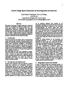
Figure 1. The default VEX cluster architecture.
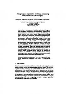
2.2. The VEX system: VLIW example VEX [2] models a scalable platform to design embedded VLIW processors that allows variation in issue width, in the number of functional units and register, and in the processor instructions set. We can distinct the three following components for VEX system. VEX ISA (Instruction Set Architecture): VEX ISA consists of a flexible architecture, modeled of the family embedded cores HP/ST Lx [3]. The basic structure of this core (cluster) is given in Figure 1. By configurating, users can build a multi-clusters VLIW architecture that is scalable and customizable to individual application domains. The scalability gives the possibility to change the number of clusters, execution units, registers and latencies. With customizability, users can define specialized instructions. A multi-cluster implementation is given in Figure 2. VEX includes a complete exposure of all architecture latencies and resource constraints:
Figure 2. A multi-cluster implementation.
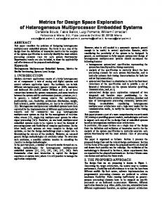
• Parallel executions units, including multiple ALUs and multipliers, • Parallel memory pipelines, • A large visible register set, • An efficient branch architecture. VEX C Compiler: Hewlett-Packard Laboratories provide a toolchain [4] with a compiler (see figure 3). In VLIW architecture, the compiler plays an important role in scheduling multiple concurrent operations. VEX compiler, a descendant of the Multiflow C compiler, includes parameter sets to allow architecture exploration by changing the cluster number, execution units, issue width, and operation latencies.
Figure 3. The structure of VEX toolchain.
VEX Simulation system: This concerns an architecture-level simulator to achieve the speed of many equivalent MIPS. The simulation system comes with a complete set of POSIX-like libc and libm libraries,
a simple build-in cache simulator and an API used to model the memory system. The Compiled Simulator (CS) translates the VEX binary to the binary of the host computer by first converting VEX to C and then invoking the host C compiler to produce a host executable (see figure 3).
3. Design Space Exploration methodology 3.1. Design space definition with VEX system With the VEX simulation environment, the source code of each algorithm possesses its own MAKEFILE which was already modified in order to use VEX compiling tools. Various flags are used by passing suitable parameters in the MAKEFILE. In the VEX compiler, several types of architecture customizations are possible. One way to customize is adding of custom instruction for a function which is taking a lot of execution time. Another way concerns the memory architecture where the parameters related to data and instruction cache can be varied. These customizations (clusters, resources, and latencies) are realized by using the custom machine configuration files which are supplied at the compile time. In this experiment, we used memory architecture customizations that are defined in cfg file. If we dont define the parameter in custom memory architecture, the default model is captured through the CS configuration file (vex.cfg). This file will be executed when it runs an application. We must also define the custom machine configuration file before running VEX compiler at the compile time in mm file because there is no default value for it. The used cluster number can be given by parameter n (n=0, 2, 4) at compile time and the default value is n=0. The total number of parameters is large (9 for machine and 9 for memory). For the design space exploration purpose, we have varied their values when generating the machine configuration files at compile time and memory architecture configuration at running application. We tried to model very wide architecture (for example 4 clusters, 32 issue slots, 32 memory operations, 32 multipliers and 32 send/receive paths), so we used the maximum value (32) for both the cfg and mm files. We wanted to know more about VEX system hardware characteristics running on very vide architecture and to obtain the best cost/performance for our application. Table 1 show the ranges of parameters to be varied for the design space. Detailed definition and description of each parameter are given in the [2]. We used also two constant parameters for total design space: CoreCkFreg =1000 and BusCkFreg =200.
Parameters IssueWidth MemLoad MemStore MemPft Alu.n Mpy.n CopySrc.n CopyDst.n Memory.n
Values 1 - 32 1 - 32 1 - 32 1 - 32 1 - 32 1 - 32 1 - 32 1 - 32 1 - 32
Parameters lg2CacheSize lg2Sets lg2LineSize lg2StrSize lg2StrSets lg2StrLineSize lg2ICacheSize lg2ICacheSets lg2ICacheLineSize
Values 5 - 32 0 - 32 4 - 32 2 - 32 0 - 32 4 - 32 2 - 32 0 - 32 0 - 32
Table 1. Parameter values ranges for machine architecture configuration mm file (left) and memory architecture configuration cfg file (right).
Parameters IssueWidth MemLoad MemStore MemPft Alu.n Mpy.n CopySrc.n CopyDst.n Memory.n
C/u 5 3 3 3 1 3 2 2 4
Parameters lg2CacheSize lg2Sets lg2LineSize lg2StrSize lg2StrSets lg2StrLineSize lg2ICacheSize lg2ICacheSets lg2ICacheLineSize
C/u 2 2 1 2 1 2 2 1 2
Table 2. Relative cost/unit (C/u) for machine architecture configuration mm file (left) and memory configuration cfg.file (right).
3.2. Cost function definition with VEX system An embedded system is a special-purpose computer system designed to perform one or a few dedicated functions, often with real-time computing constraints. Design engineers canoptimize it, reducing the size and cost of the product,or increasing the reliability and performance. Using the VEX system, twoimportant criteria have be considered: hardware cost and computing speed (execution time). All these elements have their hardware costs which can be defined. Taking into account the effect of all the parameters, a relative cost is assigned to each parameter based on simple assumptions [5]. For instance the cost of IssueWidth and ALU cannot be same since increasing IssueWidth may demand more resources, so different relative costs are assigned in Table 2 to all the parameters for machine configuration and memory configuration. The parameter n represents the cluster number; it is 0 for one cluster, 2 for two clusters, and 4 for four clusters.
For one cluster, cost of CopyDst and CopySrc is 0, as there is no inter-cluster communication. Total cost can be simply calculated as the multi plication of the number of an element with the relative cost/unit. Increasing the cluster number doesnt imply that the cost is also increased proportionality. If all the other parameters are fixed and clusters are increased that implies the reduction of overheads because of long connections with one cluster (see Figure 2). This assumption is also included while determining the cost. So the cost changes with the cluster number are calculated by the following rule: If cluster=1 Total cost=sum of all relative costs If cluster=2 Total cost=(sum of all relative costs) * 0.8 If cluster=4 Total cost=(sum of all relative costs) * 0.7 For finding out the optimal configuration, we have defined the following cost function: Cost function = execution time + cost (cluster n) with execution time = numCycles/operFrequency This function takes care of both the performance (latency) and the cost (area). We first tried to see how much resources are needed by the benchmark and then according to our cost function the algorithm tries to provide the configuration corresponding to minimum (best) cost. Here, the execution time is measured in ms.
3.3. Design Space Exploration with VEX system The simulation is performed with several steps. The VEX compiler can be used to compile for different VLIW targets just by changing specific architecture configuration files. After one architecture configuration is generated using MAKEFILE, the VEX simulator first builds the application for the corresponding machine, then executes the application to generate the log file, and finally cleans the executable to give way for the next configuration. In our experiment, one architecture configuration needs one mm file and one cfg file, and the configuration filenames are given sequentially. Every running VEX C compiler for each configuration will produce a log file using AWK programming. After that, we calculate the execution time using numCycles and operFrequency which are specified in the log file. We used Brute-force search in order to exploit the design space. Brute-force search [6] is easy to implement, and will always find a solution if it exists. However, its cost is proportional to the number of candidate solutions, which, in many practical problems, tends to grow very quickly as the size of the problem increases. Therefore, brute-force search is typically used when the problem size is limited, or when
Figure 4. Design space exploration with VEX system.
there are problem-specific heuristics that can be used to reduce the set of candidate solutions to a manageable size.The method is also used when the simplicity of implementation is more important than speed. This is the case, for example, in critical applications where any errors in the algorithm would have very serious consequences; or when using a computer to prove a mathematical theorem. Brute-force search is also useful as ”baseline” method when benchmarking other algorithms or meta-heuristics. Indeed, bruteforce search can be viewed as the simplest meta-heuristic. For our first experiment with VEX system, we wanted to know more about VLIW hardware characteristics and their performances. So we have implemented the Bruteforce search algorithm in order to browse architecture design space. To apply Brute-force search to a specific class of problems, we must implement four procedures: first, next, valid, and output.These procedures should take as a parameter c (candidate), the data P for the particular instance of the problem that is to be solved, and should do the following: 1. first (P): generate a first candidate solution for P, 2. next (P, c): generate the next candidate for P after the current one c, 3. valid (P, c): check whether candidate c is a solution for P, 4. output (P, c): use the solution c of P as appiropriate to the application. The next procedure must also tell when there are no more candidates for the instance P, after the current one c. A convenient way to do that is to return a ”null candidate”, some conventional data value that is distinct from any real candidate. Likewise the first procedure should return if there are no candidates at all for the instance P. The Brute-force method is then expressed by the algorithm: c