based on the discrete event simulator OMNET++,. Manuscript received June ... The data transfer starting time stamps as well as the end time stamps are logged ...
> 1687058669
1687058669
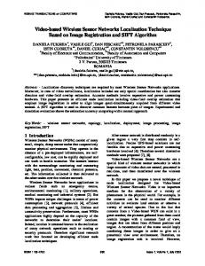
1687058669< lower OSI layers) should be designed including very detailed models for the simulation of the channel and the transmission hardware. For the development of the actual application (e.g. application layer in the OSI model) on top of those communication protocol stack models with less detail are preferred to increase the simulation speed. Aspects like energy consumption, mobility, memory usage, and microcontroller performance (including utilization) of the individual sensor nodes are not taken into account inside most of the existing solutions. Especially when other aspects such as energy harvesting are included, the environment in which the nodes exist plays an important role. For modeling and simulation of these effects the discrete event oriented simulation tools are not always sufficient, also the continuous part of the whole system should be taken into account. Within the home automation, controlling or building automation sector modeling tools with a higher abstraction level (system level) are used (e.g. Matlab/Simulink or Dymola/Modelica). The paper presented here will focus on general problems as well as covering some detailed models including all aspects described in section II. The overall goal for the future is to consider a wide range of abstraction levels when analyzing complex networking applications, including highly abstract functional models, and to put them down to network simulation problems, similar as described in [7]. V. THE SANET SOFTWARE FRAMEWORK In order to be able to simulate all aspects of Wireless Sensor Networks a framework is developed, which uses OMNET++ as core simulator. The software structure of this framework is displayed within Fig 2. The SANET framework, described in this section, is placed on top of the OMNET++ simulator and uses all functionality provided by this simulator. On top of the SANET framework there are two libraries: - Behavioral models: This library includes behavioral models for the used components (e.g. the AT86RF230 transceiver and the ATmega1281 controller from Atmel), - Structural models: This library includes the used protocol stacks, which are running on the used microcontroller. The structural model can be transferred to the real embedded system. From the components out of the two libraries described above, the sensor node can be built by describing the used components and the connections (gates & channels) between the components using the NED language provided by OMNET++. The individual nodes can then be combined together into a network, also described by the NED language. A network does not have to consist of similar nodes; each node can have an individual structure or application layer. The SANET framework contains the major part of the implementation and some aspects such as processor utilization, the wireless channel model, current consumption, and dynamic memory usage are discussed in the following sections.
3
Network Descriptions
Sensors
CPU
Node Descriptions
TRX
Component Library Transceivers, Microcontrollers, Sensors … Parent classes cBasicTranceiver, cBasicCPU, cBasicLayer, …
Behavior Models
Structural models
SANET Framework
OMNET++ Simulator
Software Stack Library IEEE 802.15.4, Zigbee, Applications … Common Aspects Channel Model, Visualization, …
Fig 2. Framework software architecture
A. Processor utilization To be able to simulate the processor utilization the execution time of the implemented code should be included. Within the simulation framework the execution times are specified using a normal distribution. The mean (μ) and standard deviation (σ) parameters are specified for each layer primitive (e.g. the DATA.request primitive) and based upon this specification the execution time is calculated each time this primitive is scheduled in the local node event queue. B. Wireless channel model For an accurate calculation of its outputs, the channel model requires some input information. The required inputs and the calculated outputs are shown in Fig 3. The channel model requires the receiver sensitivity (including the system noise) specified with S, the transmitter output power and the position of all other nodes to be able to calculate the path loss and the devices which are inside the range of the transmitter. The model will use the Friis free space equation for path loss calculation: PRX (d) =
PTX ⋅ G t ⋅ G r ⋅λ 2
( 4π )
2
⋅ d2 ⋅ L
where PTX is the transmission power in Watt, Gt and Gr the antenna gains, λ the path loss exponent and d the distance between transmitter and receiver in meters. In order to calculate the packet transmission delays, the message length and the data rate is required. For this model, the propagation delays (~300ns for 100m distance) are neglected due to the small delays compared to the actual transmission delay (4.3ms for one full IEEE 802.15.4 packet) The Signal to Interference and Noise Ratio (SINR) in dB is calculated using the system noise value of the receiver together with all devices which are currently sending according to: SINR dB
⎛ ⎜ P RXavg = 10log ⎜ k ⎜N + I ⎜ 0 ∑ i i =1 ⎝
⎞ ⎟ ⎟ ⎟ ⎟ ⎠
where PRX is the received power level from the source device, N0 the noise level of the transceiver and Ii the received power (in dB) from the ith interferer.
> 1687058669
1687058669