... CERN/AC/95-05(LHC), 1995. [2] J.B. Jeanneret, D. Leroy, L. Oberli, T. Trenkler. LHC Project ... [8] P. Sievers et al. Proc. Chamonix 2003. CERN-AB-2003-008.
EUROPEAN ORGANIZATION FOR NUCLEAR RESEARCH European Laboratory for Particle Physics
Large Hadron Collider Project
LHC Project Report 640
DESIGNING AND BUILDING A COLLIMATION SYSTEM FOR THE HIGH-INTENSITY LHC BEAM R. Assmann, O. Aberle, M. Brugger, L. Bruno, E. Chiaveri, B. Dehning, A. Ferrari, B. Goddard, J.B. Jeanneret, M. Jimenez, V. Kain, M. Lamont, F. Ruggiero, R. Schmidt, P. Sievers, J. Uythoven, V. Vlachoudis, L. Vos, J. Wenninger, CERN I. Baishev*, IHEP, Protvino, D. Kaltchev*, TRIUMF, Canada Abstract The Large Hadron Collider (LHC) will collide proton beams at 14 TeV c.m. with unprecedented stored intensities. The transverse energy density in the beam will be about three orders of magnitude larger than previously handled in the Tevatron or in HERA, if compared at the locations of the betatron collimators. In particular, the population in the beam halo is much above the quench level of the superconducting magnets. Two LHC insertions are dedicated to collimation with the design goals of preventing magnet quenches in regular operation and preventing damage to accelerator components in case of irregular beam loss. We discuss the challenges for designing and building a collimation system that withstands the high power LHC beam and provides the required high cleaning efficiency. Plans for future work are outlined.
* Members of CERN-Russia and CERN-Canada Collaborations to the LHC Project
Presented at
CERN CH - 1211 Geneva 23 Switzerland Geneva, Geneva, 5th June 2003
PAC 2003, Portland, Oregon, USA, from 12 to 16 May 2003
DESIGNING AND BUILDING A COLLIMATION SYSTEM FOR THE HIGH-INTENSITY LHC BEAM R. Aßmann, O. Aberle, M. Brugger, L. Bruno, E. Chiaveri, B. Dehning, A. Ferrari, B. Goddard, J.B. Jeanneret, M. Jimenez, V. Kain, M. Lamont, F. Ruggiero, R. Schmidt, P. Sievers, J. Uythoven, V. Vlachoudis, L. Vos, J. Wenninger, CERN, Geneva, Switzerland, I. Baishev, IHEP, Protvino, Russia, D. Kaltchev, TRIUMF, Canada Abstract
DESIGN CONSTRAINTS
The Large Hadron Collider (LHC) will collide proton beams at 14 TeV c.m. with unprecedented stored intensities. The transverse energy density in the beam will be about three orders of magnitude larger than previously handled in the Tevatron or in HERA, if compared at the locations of the betatron collimators. In particular, the population in the beam halo is much above the quench level of the superconducting magnets. Two LHC insertions are dedicated to collimation with the design goals of preventing magnet quenches in regular operation and preventing damage to accelerator components in case of irregular beam loss. We discuss the challenges for designing and building a collimation system that withstands the high power LHC beam and provides the required high cleaning efficiency. Plans for future work are outlined.
INTRODUCTION Each of the two LHC [1] rings will store 2808 bunches, each bunch populated with 1.1 · 1011 protons at energies of up to 7 TeV (nominal design parameters). The stored energy amounts to 350 MJ, two orders of magnitude beyond the achievements in the Tevatron or HERA. Comparing transverse energy densities, LHC advances the state of the art by even three orders of magnitude, from 1 MJ/mm2 to 1 GJ/mm2 . At the same time the superconducting magnets in the LHC would quench if small amounts of energy (on the level of 30 mJ/cm−3 , induced by a local transient loss of 4 × 10⁷ protons) are deposited into the superconducting magnet coils [2]. Any significant beam loss into the cold aperture must be avoided. However, beam losses cannot be completely avoided. A so-called ”primary beam halo” will continuously be filled by various beam dynamics processes and the beam current lifetime will be finite [3]. The handling of the high intensity LHC beams and the associated high loss rates of protons requires a powerful collimation system with the following functionality: 1. Efficient cleaning of the beam halo. 2. Tuning of the halo-induced experimental backgrounds. 3. Passive protection of the machine aperture. In addition the integrity of the system must be maintained during regular and irregular operational conditions. The challenges for designing and building an appropriate system are discussed.
The collimation system must fulfil a number of important design constraints, which are listed below for proton operation. Similar constraints must be fulfilled for operation with ions. Beam loss rates Regular LHC operation is assumed to include short periods of reduced beam lifetime. At 7 TeV the collimation system should accept losses of 4.1 · 1011 p/s (0.2 h lifetime) for 10 s or 0.8 · 1011 p/s (1 h lifetime) continuously. Cleaning efficiency Assuming the above beam loss rates, the expected quench levels and nominal intensity, the required local cleaning inefficiency is calculated to be 2 · 10−5 m−1 [4]. The local inefficiency is defined as the inefficiency (number of halo protons reaching ≥ 10σ per impacting primary proton) divided by the length over which losses are spread (e.g. 50 m). Number of collimators and phase advance requirements The above mentioned goal for cleaning inefficiency can only be achieved with a cleaning system that has at least two stages with collimators put at special phase advance locations [5]. Momentum and betatron cleaning must be performed separately. Cleaning systems based on aluminium and copper jaws have been integrated into the LHC layout and optics. The jaw materials and lengths are being reviewed and the IR3 and IR7 insertions must be adapted to the final design choices. In the old design 5 collimators per beam (1 primary and 4 secondaries) provide momentum cleaning in IR3 and 20 collimators per beam (4 primaries and 16 secondaries) provide betatron cleaning in IR7. The goal efficiency is achieved. Some additional absorbers are required to capture the proton induced showers in the cleaning insertions. An eventual opening of collimator gaps would require additional collimators at the experimental insertions. Beta functions in cleaning insertions Ideally, beta functions should be large at the collimators in order to alleviate the consequences if some bunches impact on the jaw. However, the available space in the warm cleaning insertions limits the beta functions to values of 50 m to 350 m (IR7) [5]. Corresponding transverse beam sizes are small, from 160 µm to 420 µm at 7 TeV.
Collimator gaps The available LHC physical aperture is about 10 σ both at injection (limited in arcs) and at 7 TeV (limited at triplets). The primary and secondary collimators must then be closed to nominally 6 σ and 7 σ, respectively, for providing the required cleaning inefficiency at 10 σ. The corresponding collimator full gaps at 7 TeV are small (2.2 - 4.4 mm). It is noted that there is some flexibility in the collimator settings [6]. relevant Operational and mechanical tolerances The tolerances derive directly from the difference in settings between primary and secondary collimators (1σ ≈ 200µm), as well as from the impact parameter at the secondary collimators (average impact parameter is 200 µm). Tolerances are a fraction of these values. For example, the tolerances for transient orbit movements and transient beta beat were determined to be 0.6 σ and 8%, respectively. Tolerances can be estimated for jaw surface flatness (≈ 25µm), reproducibility of jaw settings (< 20µm), resolution in jaw movements (≈ 1µm, ≈ 1µrad) and knowledge in collimator gap < 50µm. Some trade-off between different tolerances is possible. Impedance The collimators can produce significant transverse resistive impedance due to the small gaps at 7 TeV (impedance scales inversely proportional to the third power of gap size). At nominal beam intensity, the LHC octupoles provide Landau damping of the rigid dipole modes for a total collimator impedance of up to 110 MΩ/m, to be compared with an impedance of 100 MΩ/m generated by the rest of the ring. Shock beam impact In case of irregular beam dumps several bunches can be deflected on a collimator jaw. Any jaw can be hit, because the primary collimators only cover one phase space location and the overall LHC tune should be allowed to vary. The collimator hardware should withstand beam impact during irregular dumps. The expected maximum beam impact was calculated to be about 20 bunches [7]. Recently this value was reduced to about 8 bunches, due to a substantial improvement in the dump re-trigger time. The presently ongoing material studies still use as input the now pessimistic, old scenario. Reliability and maintenance The lost protons will activate the installations in the cleaning insertions leading to maximal dose rates of up to several mSv/h at direct accessible hot-spots, e.g. shielding or downstream magnets. The collimator jaws may reach higher values. The expected dose rates depend strongly on the collimation layout, the materials chosen, the cooling time as well as the exact location in the insertion. However, human interventions such as maintenance nearby highly activated installations must be restricted to the absolute minimum, hence collimators and belonging equipment must be designed for maximum reliability. Detailed studies are ongoing.
Vacuum aspects The collimators must be bakeable and outgassing rates must remain acceptable. For example, for a graphite collimator this imposes special heat treatment, careful outbaking, and a maximum jaw temperature of 50◦ C, to be assured by collimator cooling. Graphite dust is believed to be uncritical. The magnitude of a local electron cloud and its possible effects are being studied and outgassing measurements are being performed. The design of the collimation hardware should address these constraints in a consistent way, even though some constraints support conflicting preferences.
MATERIAL STUDIES The present baseline collimation system for the LHC relies on aluminium and copper jaws, as used in LEP. These choices do not allow collimator survival e.g. during irregular dumps. If about 10−5 of the stored 7 TeV beam intensity is lost in a single turn on one copper collimator damage can occur. The losses during irregular dumps are more than two orders of magnitude above this damage threshold.
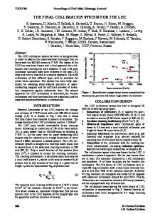
Energy Deposition in Various Materials The expected beam impact distribution for irregular dumps [7] was used to calculate the energy deposition versus jaw length in various materials (see also [8]). FLUKA [9] was used to perform a full shower study. The predicted peak temperature rise is shown in Fig.1. It is seen how the shower develops along the length of the jaw. The length of secondary jaws, as required for achieving the desired cleaning efficiency, varies between 0.5 m for copper and 1.0 m for graphite or beryllium. The temperature rise for these lengths is large, ruling out high Z materials for the bulk of the collimator jaws as well as for thin coatings on jaws made of low Z material. Shorter primary jaws (a few cm to 20 cm) are less critical. As possible candidate materials graphite and beryllium are retained. Other FLUKA studies have been performed (required thickness of graphite layer, injection impacts) and some others are under preparation (fiber-reinforced graphite, copper doped graphite, ions, slow losses in 200 nm surface layer, energy deposition downstream of jaw, input for electron cloud estimate).
Fatigue and Stress Analysis The FLUKA results are used in the ANSYS program to predict stresses. The static stresses were calculated for fine-grain graphite and beryllium (for the 7 TeV irregular dump). It was found that static stresses for graphite are about a factor of 2 and for beryllium about a factor of 5 beyond the engineering tolerance. Dynamic stresses usually further increase the stress values by a factor of 2. Detailed dynamical calculations are being done. In addition, ANSYS calculations are planned for fiber-reinforced graphite, copper doped graphite, ions and injection cases.
Temperature Rise (∆T oC)
2000
performance are under study. It is also investigated whether copper doped graphite has a better impedance for similar robustness.
100 µm Copper Coating
1800 1600
Aluminum
1400 1200
SUMMARY AND OUTLOOK
Graphite
1000 800 600 Beryllium
400 200 0 0
20
40
60
80
100
120
140
160
Length z(cm)
Figure 1: Temperature increase (peak) from 20◦ C versus collimator length for different materials. Input is the proton impact distribution from an irregular dump at 7 TeV (single-module pre-trigger with a 1.3 µs re-trigger time). Approximately 20 bunches impact on the jaw face. The ANSYS results will allow selecting the material with the best mechanical properties for LHC collimation. It is too early for any final conclusions at this point, however, graphite looks most promising. Taking into account the recent factor 2.5 reduction in beam impact (improved LHC dump re-trigger time) and a factor of 2 increase for dynamic stress, it is seen that fine-grain graphite is less than a factor of two away from the design target. These graphite jaws would survive most irregular dumps at nominal intensity and would have appropriate robustness for running during the first years of the LHC where the total intensity will be limited to 50% of the nominal. It is hoped that fiber-reinforced graphite will show even better mechanical resistance.
Impedance The transverse resistive impedance was evaluated for the collimators, assuming nominal gaps at 7 TeV, nominal intensity, and different materials. Large impedance was found, ranging from 100 MΩ/m for copper jaws to 1050 MΩ/m for graphite jaws. While the copper-based solution is acceptable for impedance and unacceptable for robustness, the graphite-based solution is almost acceptable for robustness but unacceptable for impedance. A full beryllium-based system has insufficient robustness. A solution with graphite jaws in the horizontal plane (the dump sweep is horizontal) and beryllium jaws elsewhere would allow to reduce the impedance to about 300 MΩ/m. This is still unacceptably large and in addition the use of beryllium would introduce additional safety concerns. The conflicting requirements prevent a straight-forward solution. More elaborate solutions are being investigated. For example, a graphite-based collimation system might have acceptable impedance with a different collimation strategy, where secondary collimators are opened to about 10 σ. Possibilities to achieve this without constraining the LHC
The design challenges for the LHC collimation system have been reviewed, giving a list of specific constraints. Possible jaw materials are being studied with the goal of building collimators that can survive the expected conditions during LHC operation, including irregular dump actions. This would avoid the use of more elaborate and possibly more expensive concepts like ”consumable” or ”renewable” collimators. At present no appropriate jaw material could be identified. Graphite is very promising in terms of robustness but generates unacceptably high transverse resistive impedance. The use of a graphite-based collimation system would require a different collimation strategy that uses larger gaps. This is being studied but would require additional collimators close to the experimental interaction points. In addition hybrid solutions (graphite/copper, graphite/beryllium) and more advanced materials (copper doped graphite) are being investigated. Concepts of ”consumable” or ”repairable” jaws are considered with still lower priority. The mechanical design of the collimator tanks, the jaws themselves, the cooling, etc is being addressed in parallel to the material studies. Once a material has been selected and the mechanical layout has been chosen, a prototype will be built for April 2004. After successful prototype testing the production of about 66 collimators and additional spares will be started. The collimators would be installed in 2006 and be ready in time for LHC commissioning in 2007. Collimation for the LHC is a difficult task offering many interesting challenges. The commissioning, operation, and understanding of the system will be an opportunity to learn about handling of high-intensity proton beams in a completely new regime.
REFERENCES [1] The Large Hadron Collider, CERN/AC/95-05(LHC), 1995. [2] J.B. Jeanneret, D. Leroy, L. Oberli, T. Trenkler. LHC Project Report 44 (1996). [3] R. Assmann, F. Schmidt, F. Zimmermann, M.P. Zorzano. LHC-PROJECT-REPORT-592. EPAC02. [4] R. Assmann et al. LHC-PROJECT-REPORT-599. EPAC02. [5] J.B. Jeanneret. CERN-LHC-Project-Report-243 (1998). [6] R. Assmann. Proc. Chamonix 2003. CERN-AB-2003-008 ADM. [7] R. Assmann, B. Goddard, E. Vossenberg, E. Weisse. LHCPROJECT-NOTE-293 (2002). [8] P. Sievers et al. Proc. Chamonix 2003. CERN-AB-2003-008 ADM. [9] A. Fasso, A. Ferrari, J. Ranft, P.R. Sala. Proc. of the Int. Conf. Monte-Carlo 2000, Lisbon, Portugal, Oct. 23-26, 2000, p. 955, Springer-Verlag Berlin Heidelberg (2001).