!999ttthhh IIInnnttteeerrrnnnaaatttiiiooonnnaaalll SSSyyymmmpppooosssiiiuuummm ooonnn MMMuuullltttiiipppllleee---VVVaaallluuueeeddd LLLooogggiiiccc
Designing and Using FPGAs Beyond Classical Binary Logic: Opportunities in Nano-scale Integration Age Zeljko Zilic McGill University, Montréal, Québec, Canada
[email protected] As the elements are now being put in place to allow the wider use of multi-level signaling, storage and logic function computations, especially in conjunction with emerging technologies, this paper aims at overcoming the mistakes and omissions of the past, as a way towards MVL FPGAs.
Abstract In this paper, we first recap the rationale beyond the (non)-acceptance of multi-valued logic in implementing FPGAs so far, explaining the most critical technological and tool support details. Then, we outline the critical applications of FPGAs (e.g., emulation) where the nonbinary nature can be exploited by MVL implementation. Finally, we highlight the most significant opportunities that present themselves with the transition to the nano-scale system implementations.
2. Background: Designing FPGAs with MVL From historical perspective, FPGAs are best placed in the context of Mask-programmable Gate Arrays (GAs), the technology that has had its prime in early 1980’s. In this technology, all the possible gates were first laid down. The users only needed to add (i.e., “program”) interconnect. From this perspective, FPGAs offered an evolutionary improvement in providing the control of those switches by SRAM memory cell, hence the in-field programmability feature. There also existed the low-end Programmable Logic Devices (PLDs), mostly as two-level AND-OR: PAL or PLA devices could implement few functions and even be reprogrammed, after erasing them with UV light. It was however overlooked that FPGAs were not only the incremental improvement. The most significant consequence was in not anticipating the level of required software tool support. While mask-programmable GAs were fully usable with only a specialized router tool for making them usable, each FPGA user is fully dependent on a number of capable software tools for mapping logic to this new technology. The tool needs increased with the advance of the more modern design entry means, especially the high-level design languages (HDLs) such as Verilog or VHDL. Indicative of this omission was the fact that all major IC manufacturers (TI, AMD, Intel, IBM, Motorola, AT&T/Lucent, NEC, Toshiba, Philips, ST…) had their programmable logic products and are now out of this market. The reason is not in hardware, but in the need to maintain the complex software.
1. Introduction The emergence of Field Programmable Gate Arrays (FPGAs) in mid 1980-s has played trailblazing and transformational roles in the Integrated Circuit (IC) industry, especially the Application-specific IC (ASIC) part of it. Numerous issues appearing first in FPGAs have later become acute within more custom ICs and even point to the issues that will appear with the emerging integration of nanoscale devices. For instance, the delay in interconnect has been the dominant part in FPGAs from beginning– due to the shrinkage in technology, delays in wiring have become more dominant everywhere. More importantly, as FPGAs have dramatically lowered the time and capital cost threshold for IC implementers, they have taken much of the ASIC markets, and have created several markets on their own, where the reconfigurable nature of FPGAs is used for various computational, modeling and system validation purposes. In considering FPGA innovation, it is hence critical to consider both their design and the usage. One worthy innovation to FPGAs is in the use of multiple-valued logic and signaling. Since over 75% of the area in FPGAs is occupied by interconnect, using higher radices can significantly reduce area. The predominant concern nowadays is the energy consumption, which is ever more dominated by wiring, including clock distributions, since interconnect is associated with significantly higher capacitive load. The MVL in FPGAs can greatly help in the energy aspect as well [5], [6]. Regarding FPGA design challenges, upon their invention there was little understanding of what support will FPGAs need, which not only stymied viable MVL FPGAs, but also stopped major IC makers in maintaining their binary FPGA products. Further, the roles that MVL can play in FPGA applications were overlooked, which needs to be corrected. !111999555---666222333XXX///!999 $$$222555...!! ©©© 222!!999 IIIEEEEEEEEE DDDOOOIII 111!...111111!999///IIISSSMMMVVVLLL...222!!999...555111
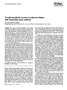
2.1. FPGA Design Challenges The FPGA hardware nowadays consists of the programmable logic substrate and a large number of dedicated parts, such as clock generators and distributions, multi-standard IO peripherals, including high-speed serial interfaces (HSSIs) Figure 1. Because of their wide applicability, FPGAs are only bound to include more of such a diverse hardware in the future. Programmable logic substrate in FPGAs consists of the array of logic blocks (LBs) and the interconnect between
222666888
Authorized licensed use limited to: McGill University. Downloaded on November 27, 2009 at 00:29 from IEEE Xplore. Restrictions apply.
them. Each LB is commonly a cluster of the unit programmable logic blocks, mostly based on lookup-tables (LUTs). To speed up common arithmetic functions, LUTs are augmented with specialized circuits that assist in providing faster arithmetic blocks, such as the carry logic used for adders and multipliers. Hence, LBs are by now relatively complex blocks, especially when compared to the early implementations, which were simply LUTs.
the design of Xilinx XC3000, for a next decade has been competing very favorably to Xilinx devices in several performance metrics. For companies that have their fabrication facilities, FPGAs served as a technology driver, to try out all the elements of their process, especially SRAM. The core of FPGA circuitry consists of SRAM logic cells and switches controlled by them, plus the implementation of LUTs. Over time, the clocking subsystem gained in importance as well. The common design practices for those blocks include: managing the strengths of competing driver transistors, especially with the purpose of starting up in a known state (usually, memories initialized to 0), avoiding shoot-through in memory cell scans, and keeping (mostly pMOS) transistors controlling the switches at sufficient voltages for pass transistors to completely open and close. The main theme in FPGA block design is that of emphasizing the latency reduction, as FPGAs are at speed disadvantage relative to ASICs. For reducing latencies, very common technique is that of flattening the 2n:1 multiplexers, by which the depth is reduced from n to one pass transistor (sometimes one transmission gate) via decoding the control bits for each of the 2n such pass transistors connected to the common multiplexer output, Figure 2. Multiplexers are a very common element in FPGAs, and such flattening is applied in numerous instances when the control signals are not in the critical path - most often, they are static, i.e., driven by the configuration SRAM. We note that such flattening should be also favorable for the use of MVL. Pass transistors and gates can pass reduced voltage swing MVL signals, and reducing the number of levels helps in reducing signal degradation. Also, joining together the decoder logic creates more room for savings in MVL implementations of a multiplexer by sharing the logic for literals and their products. However, besides an earlier RTD-based MVL design of the flattened MUX [1] with a single control signal, we are not aware of more recent such MVL implementations, either in LUTs or elsewhere.
Figure 1: FPGA layout – main blocks of modern FPGAs
Interconnect is in many ways the most critical and complex part of the programmable substrate of FPGAs. It provides for a variety of multi-segmented routes between LBs, under vastly different communication patterns, from local to moderately and fully global. To provide for a mix of such patterns, interconnect is very intricate, and most often composed of several independent parts and multi-segmented, each specializing in a different aspect of communication (e.g., dedicated wires between neighboring blocks, segments spanning !, " and the whole length of FPGA, etc.). In addition to interconnect segments of various lengths and interconnection patterns, needed are the switch modules (SMs) that connect different wire segments and the connection modules (CMs), which connect the logic blocks to the interconnect.
2.2. Design Practices in FPGA Hardware Figure 2: Flattening MUXes is common technique in FPGAs
Since their introduction, the design of FPGA blocks has advanced tremendously in all its aspects, starting from the circuit level, and ending at the system-level design. The original design of the early Xilinx XC3000 FPGA series was relatively simple and unsophisticated, and harboring in itself a couple of design flows that lead to the latchup and other problems in several generations of Xilinx and AT&T/Lucent FPGAs that were derived from it. As a separate testimonial to the room for improvement that existed in the original Xilinx FPGA design, it’s been known that the ORCA FPGA family, which AT&T has conceived after being outsourced
With diversification of FPGAs and their uses, lot of innovations changed virtually all the aspects of the FPGA design, from the devices, to circuits and the system-level design practices. For instance, with predominance of pass gates in LBs and interconnect, early FPGAs were well modeled at switch level, i.e., with individual transistors being treated as bidirectional switches. The sheer complexity and the variety of blocks in modern FPGAs require higher levels of abstraction in modeling and design approaches. While the critical core for achieving MVL FPGAs is in 222666999
Authorized licensed use limited to: McGill University. Downloaded on November 27, 2009 at 00:29 from IEEE Xplore. Restrictions apply.
same time, the device variability has increased. To overcome issues with voltage as the carrier of information, the idea of using current as an information carrier has been popularized through several mixed-signal design approaches, focusing on the use of current mirrors as main building blocks, resulting eventually in current mode CMOS logic (CMCL). Following such a design style, we have attempted to design the main FPGA blocks to operate as MVL devices in current mode [7]. Further, work in [5] studies both current and voltage mode LUTs, and shows that the current mode ones operate faster. Current mode logic requires static current, which becomes unbearable at high levels of integration present in modern FPGAs. Other conclusions from that effort was that while the current mode does remove the constraints of shrinking voltages, the introduction of current mode signals cannot fully eliminate voltage-mode signals, leading to the problems with having several types of signals (binary voltage, binary current and MVL current), with the increase of rules and, to an extent, wiring to worry about. The consequence was that of needing to have in parallel the current- and voltage-mode signal networks.
10 11 01 00
Type1
Type2
Type3
Figure 3: Multilevel signal decomposition for clock recovery
the programmable logic substrate, all parts of FPGAs can be now considered as candidates for employing MVL design. For instance, in widely used HSSI IOs, the 4-level signaling (known as PAM-4) was considered [2]. To decode four different levels corresponding to two bits of information, and to extract the clock, the receiver has to recognize three different types of transitions, Figure 3, depending on how large signal jump was made. This transition-based style of the design in clock-data recovery (CDR) differs from the classical combinational literal-based MVL design and requires careful jitter, interference and scaling analysis [3].
2.3. Voltage Mode MVL FPGA Implementations
3. MVL in FPGA Applications: Validation
Considering MVL implementation of FPGAs comes most naturally by extending the classical FPGA circuitry to higher radices, as outlined in previous section. The most commonly considered were the implementations of logic blocks based on lookup tables. In [4], the authors consider the design of quaternary LUT blocks, and compare them with binary LUTs. When facing reduced noise margin, one might need to use multiple transistor threshold, or even several different voltage supplies, even when designing only LUT blocks. Further, work in [6] considers the MVL design of all major FPGA blocks by cells using quaternary Si/SiGe inter-band tunneling diodes (ITDs). The design style applied is reminiscent of the quaternary RTD designs from the past, including the memory cells, in which three ITDs are stacked. One area where the immediate contribution is needed is that in the means of overcoming the problems caused by variability, which only get magnified with MVL gates. Needed are sufficiently detailed and realistic analytical and experimental schemes to evaluate and combat the variability impact. We are not aware of such studies in conjunction with MVL FPGAs, unlike the earlier work on assessing the variability effects on multivalued Flash memories [8].
FPGAs are being used in a wide range of disparate applications, from “glue” logic to the control and DSP circuits, to reconfigurable computing. They have created rich “ecosystems” that are application-driven and critically depend on how well the applications map to FPGAs. For MVL FPGAs, it is easy to see that higher radices can be useful in arithmetic and DSP applications, see [5]. This section outlines the system validation application of FPGAs, where we will see that the true MVL encoding and computation is not just useful, but a must for wider acceptance, relative to the alternative technologies.
3.1. Prototyping and Emulation of Digital Logic The ability to quickly prototype logic and even try it in its intended environment has been undoubtedly one of the major competitive advantages of FPGAs. There are numerous examples of projects that have benefited from building FPGA prototypes, but also of the projects where the lack of such prototype and the reliance on fabricating anASIC or custom IC meant the infamous end to the project. For validation of logic, there is now a sizeable emulation industry that adds the value by providing the emulation platforms that are very capable to assist in prototyping, debugging and thoroughly evaluating the design before it is committed to an IC. FPGAs have been historically a critical technology for emulation business, but in large part due to inability of processing multiple-valued state in FPGA, highend emulators use now dedicated processors. When the cost of the emulator is to be kept affordable, FPGAs are still appealing. The recent companies in emulation (Eve, Chip-It) and simulation acceleration (LIGA) all use FPGAs in innovative ways, to provide new, cost-efficient ways to
2.4. Current Mode MVL FPGA Implementations The main difficulty with the voltage-level MVL techniques is in the fact that due to the device shrinking by the constantfield principle, voltage budget gets smaller. Historically, in the second decade of FPGAs, the feature sizes went from 0.5 #m at 5V, to 0.18 #m and 1.8V supply. With the shrinkage reaching the 40 nm technology node with some current FPGAs, the tolerances to error have decreased while, at the
222777!
Authorized licensed use limited to: McGill University. Downloaded on November 27, 2009 at 00:29 from IEEE Xplore. Restrictions apply.
assist in bringing bug-free designs to the market. Regarding the emulation functionality, the baseline platform provides a “true-circuit” simulation service, but they increasingly have to be augmented with two major extras: 1) test sequence generation and evaluation for dynamic verification/validation and 2) assertion-based verification (ABV) support, with the basic service being that of the checking the assertions, which is most suitably done via generating hardware checkers of assertions [10]. 1) True Circuit Emulation: Here, the basic service is to execute HDL code on emulation hardware. The languages such as VHDL and Verilog have well-defined semantics for simulation by which, even for purely binary digital designs, having two-valued logic is not enough. Multiple-valued logics, with anything between 3 and 9 logic levels have been defined for simulation semantics purposes, to express all the combinations of undefined, high impedance, as well as the different signal strength that suffice for describing common circuits. Because of the absence of MVL FPGAs, the market still has a heavy presence of purely binary, 2-valued Verilog emulators. Much more useful is 3-valued Verilog modeling, the third value being “x”, or undefined/uninitialized: their makers still require a premium for 3-valued Verilog. Hence, this is clearly an area where the MVL FPGA provides the strategic advantage. With 3-valued FPGAs, every binary gate to be modeled would be implement es ternary, with xvalued semantics. For instance, an AND gate model would perform “*” operation with “x” as x*0=0, x*1=x, while OR gate emulates x-valued “+” as: 0+x=x, 1+x=1. 2) Assertion Checking Emulations: The single most important recent trend in design validation is that of ABV. Assertions are statements describing the designer intent, i.e., snippets of specification that can be added conveniently at any stage during the design process. By now, assertions are indispensable in virtually all design houses, where the examples of designs with close to hundred thousand assertions are not uncommon. To use assertions in emulations, one has to devise the techniques that efficiently check whether the assertions hold [10].
stage of simulation based verification eventually leads to property satisfaction or failure, Figure 4. Other assertion checker tools [12] employ two bits for checking each assertion, to similarly encode the signal levels for each ongoing assertion check. Since assertion checkers are very costly for increasingly complex temporal assertions in modern hardware designs [11], serving this particular application with multiple logic values would results in direct savings and enrichment of capabilities of FPGAs for the mainstream verification purposes.
3.2. Real-Valued and Quantum Circuit Emulation FPGAs are increasingly used to model and emulate the behavior of continuous-time, continuous-value systems. While the discretization in time and functional domain is a must with binary FPGAs, these demanding applications can significantly benefit from MVL FPGAs, but also the FieldProgrammable Analog Arrays (FPAAs). 1) Communication Channel Emulation: The emulation concept has been extended to real-valued systems, such as communication channel emulation, where the emulator is equipped with the ability to evaluate the Bit Error Rate (BIT) as a function of Signal-to-Noise Ratio (SNR). Such specialized emulators [13] require state-of-the art generators of Gaussian random variables of high quality [14] with a number of innovations needed to be useful on common offthe-shelf FPGAs, as there is little binary information there. 2) Quantum Circuit Emulation: A significantly more involved use of multi-valued representation of data arises in the emulation of the quantum circuit behavior by FPGAs. The work in [15] presents a quantum circuit emulator that deals with the quantum bit (qubit) representation via a pair of complex numbers. Actually, using d-valued qudits as carriers of quantum information was shown advantageous [16] in requiring less resources and converging faster. In quantum circuits even with only binary basis states, |0> and |1>, every qubit is represented by a pair (!, ") of complex numbers. There is theoretically an infinite amount of information that could be stored in a qubit as !|0> |+ "|1>, shown in green in Figure 5. Since errors in binary representation of such data are inevitable, the quantum circuit emulator needs to include techniques for providing the sufficient precision of complex-valued presentations, and deal with the errors in representation and computation over the approximations of the data values [15].
Figure 4: Logic values in MBAC assertion checker [11]
An interesting aspect of checking the assertions, but also of all the hardware verification uses of emulators is that the assertion checker result cannot be expressed as a binary value. Our assertion checker, MBAC recognizes the four levels of property satisfaction, which, depending on the
Figure 5: Qubit representation and error handling
222777111
Authorized licensed use limited to: McGill University. Downloaded on November 27, 2009 at 00:29 from IEEE Xplore. Restrictions apply.
4. Nano-Scale Integration Opportunities
companies already produce such memories, including the spinoffs of Cypress and Freescale (MRAM), joint Intel-ST venture and Samsung (PCRAM). The potential to store several levels of information has been already explored. The published Intel-ST PCRAM design is already using a 4-level MLC memory cells [19]. In fact, PCRAM appears now to be the most competitive with Flash in terms of area density, where for both the use of MLC cells has provided the competitive edge.
The greatest opportunity for wide MVL acceptance exists in conjunction with the emerging technologies that allow the nano-scale integration. The increased scaling again favors regular structures, which help in dealing with increased complexity. Even though the technologies are new or emerging, we believe that much of the change in increased MVL use will be surprisingly evolutionary, akin to the way that the Flash memory had become accepting of multilevel encoding of storage data in their multi-level cells (MLCs), which have been sold for a number of years by Intel and others. In addition to overcoming the purely technological challenges, there is a lot of challenges and opportunities for the circuit designers designing interfaces between possibly disparate technologies and signal carriers, as well as the system designers, providing reliable operation of the overall system. As we saw, both the voltage-mode and current-mode approaches present significant difficulties for multi-valued storage and processing of information in FPGAs, the emerging technologies often employ some other carriers of information, such as spin, molecular state, phase state and polarization [17], where the above limitations are mitigated, and we will point to some existing solutions, albeit at the cost of new interface challenges if the parts of the systems need to be done in traditional way, such as in CMOS. In looking into FPGA MVL possibilities, we first consider the part that has been less explored, until recently. The underlying memory system has not been in focus of FPGA architects, yet some of the most impactful recent changes deal exactly with the storage of FPGA configurations and the information being processed, more specifically, a push for non-volatile memory (NVM).
4.2. Interconnect The concept of nanowires, in conjunction with regular, repeatable structures could be applied to FPGAs and their interconnect, although the challenges here are significant. Nanowires are the tiny structures, so much that they can essentially be considered as 1-D objects. They differ in just about all aspects from classical semiconductor interconnect, enough so that their direct replacement with nanowires is not conceivable without many complications. Their conducting properties, the discretization in the transport characteristics, small size, inability to restore levels and numerous reliability issues present the interfacing to classical wires a major problem. Similar host of issues holds to carbon nanotubes and molecular devices in general [20]. A number of solutions to interfacing nanowires were proposed that would lead to widely differing architectures, but it is important to notice that FPGAs, by being the regular structures, are near to the top of intended beneficiaries of nanowire integration, next only to memories. The initial broad considerations of technologies for nanoscale integration of FPGAs showed the possibility of saving 70% of the FPGA area, in addition to performance and energy consumption improvements [20]. A significant number of architectural re-considerations are shown to be required, with the initial studies showing the preference for segmented routing. A number of studies were done since, concentrating on the ways to connect to the nanowires, the architectural (and tool) implications, as well as some practical realizations were demonstrated.
4.1. Memory Subsystem The largest immediate promise for MVL use is in the memory for FPGAs, both the programming bits as well as the embedded memory blocks. While the mainstream FPGAs use SRAM cells for all such memory needs, the temptation has existed to employ NVM: EEPROM have been used in PLDs and CPLDs, but and recently the Flash memory has been reexamined to keep FPGA memories nonvolatile. Up to recently, such efforts were frustrated due to the need to still keep SRAM cells to copy all bits from a NVM. At least two major makers, Actel and Lattice, now offer Flash-based FPGAs, with others facilitating ever tighter integration with the Flash memories. The Flash-based FPGAs exhibit now the largest growth rate among FPGAs, with their superior energy efficiency and boot up time. Looking forward, close to dozen technologies are nearing commercialization that could revolutionize the memory, with the promise of providing “universal memory” [18], replacing everything from SRAM and DRAM to Flash and hard disks. These technologies include Magnetoresistive RAM (MRAM), Phase Change RAM (PCRAM), as well as the IBM’s Racetrack Memory. Besides IBM, several
Figure 6: Connecting nanowires in CMOL FPGA
Achieving the reliable interfaces to the nanowires dominates the list of challenges. Depending on technology used, several approaches arose. Most often considered is the use of the decoder techniques for overcoming the problem. A geometrical approach was proposed by Strukov and Likharov [21], where an angle to the nanowire orientation is akin to decoding in connecting gates to nanowires at smaller pitch, Figure 6. The decoder approach considers the combination of the nanowires and the larger scale CMOS interconnect as a 222777222
Authorized licensed use limited to: McGill University. Downloaded on November 27, 2009 at 00:29 from IEEE Xplore. Restrictions apply.
crossbar, where the two sets of wires run perpendicular to each other. Since the nanowires are beyond the lithography scale for CMOS and no direct connection can be placed, considered instead are the alternatives. In the case of gateall-around silicon nanowires, the doping modification in the substrate creates FET transistors. The classical wires can act as transistor gates control such FETs. A collection of such transistors are imprinted to perform the decoder function. The combinations of gate voltages on classical wires then controls the resistivity along the nanowires, acting in a way analogous to the pass transistor use in FPGA interconnect. The place where MVL can help the most is in connecting to nanowires via the decoder approach. The work on using MVL for connecting nanowires in memories has been recently elaborated [24]. Here, the control of the doping level effectively results in multi-threshold gates, where MVL signaling in classical wires directly leads to the increased information density and lower wiring requirements in classical interconnect. The reduced voltage levels and increased variability are addressed by the error correcting approach, similar to past considerations in conjunction with MLC memories [9]. Extending this MVL approach to nanowire interfacing via decoding to FPGAs presents many exciting research challenges, including those at system-level and in software.
[2] [3] [4] [5] [6]
[7] [8]
[9] [10] [11] [12]
5. Conclusions and Future Directions
[13]
We have reviewed issues dealing with the acceptance of new FPGA architectures, with the emphasis on the FPGAs that go beyond binary logic. The diversification and the inclusion of many specialized blocks has made modern FPGAs extremely complicated, but it also offers the opportunities for MVL use in new places, such as HSSI devices. The architects need to thoroughly understand the needs of system support, including a rich software base, such that every new proposal has a clear path to securing all the needed support. Further, we have shown a strategic advantage for MVL FPGAs in capturing markets for emulation and validation. Emerging nanotechnologies provide very good match with FPGAs, due to the preferences towards regularity. A number of areas were identified where MVL adds value, with others, such as MVL holographic memory for FPGAs, left outside the scope. As the previous MVL FPGA proposals face increasing challenges if done as either voltage- or current-mode, most needed is a solid way to deal with reduced energy budgets and increased variability in providing reliable computation and signaling. Further, even though we did not discuss the rich set of testability challenges, resolving them is a must for technologies and architectures nearing commercialization. Areas such as FPAAs, and the use of quantum information processing are worthy to investigate within this framework.
[14] [15] [16] [17] [18] [19]
[20] [21] [22]
[23]
[24]
References [1]
H. L. Chan, S. Mohan, P. Mazumder and G. I. Haddad, “Compact Multiple-valued Multiplexers using Negative Differential Resistance
Devices”, IEEE Journal of Solid-State Circuits, Vol. 31, No. 8, Aug. 1996, pp. 1151-1156. K. L. Lim and Z. Zilic, "A Novel Phase Detector for PAM-4 Clock Recovery in High Speed Serial Links", Proc. IEEE International System on Chip Conference, SOCC’04, pp. 151-152, Sep. 2004. F. A. Musa and A. Chan Carusone, “Modeling and Design of Multilevel Bang-bang CDRs in the Presence of ISI and Noise”, IEEE Transactions on CAS I, Vol. 54, No. 10, pp. 2137-2147, Nov. 2007. R. Cunha, P. Boudinov and L. Carro, Quaternary Look-up Tables Using Voltage-Mode CMOS Logic Design, Proc. IEEE Intl. Symp. Multiple-Valued Logic ISMVL’07, 2007, pp. 128-513. A. Sheikholeslami, R. Yoshimura and G. Gulak, “Look-up Tables for Multiple-Valued Combinatorial Logic,” Proc. ISMVL’06, 2006. P. Kelly, T. McGinnity and L. Maguire, “Reducing Interconnection Resource Overhead in Nano-scale FPGAs through MVL Signal Systems, Proc. Intl. Conference on Application-Specific Systems, Architectures and Processors, ASAP’05. Z. Zilic and Z. Vranesic, “Multiple-valued Logic in FPGAs”, Proc. Midwest Symp. Circuits & Systems, pp. 1553-1556., 1993. Y-G. Kim, S-H. Lee, D-H. Kim, J-W. Im, J-S. Doh, S-E. Yu, D-W. Kim, Y-K. Park and J-T. Kong, “Sensing Margin Analysis of MLC Flash Memories using a Novel Unified Statistical Model”, Proc. Intl. Symposium on Quality Electronic Design, ISQED,’06, pp. 41-45. B. Polianskikh and Z. Zilic, "Induced Error-Correcting Code for 2bitper-cell Multi-Level DRAM", Proc. IEEE Midwest Symposium on Circuits and Systems, pp. 352- 355, Dayton, OH, Aug. 2001. M. Boulé and Z. Zilic, "Incorporating Efficient Assertion Checkers into Hardware Emulation and Simulation", Proc. IEEE International Conference on Computer Design, ICCD’05, pp. 112-117, Oct. 2005. M. Boulé and Z. Zilic, "Generating Hardware Assertion Checkers for Hardware Verification, Emulation, Post-fabrication Debugging and On-line Monitoring”, Springer, 2008. D. Borrione, M. Liu, P. Ostier and L. Fesquet, “PSL-Based Online Monitoring of Digital Systems, Chapter 1. in Applications of Specifications and Design Languages for SoCs, Springer, 2005. Y. Fan and Z. Zilic, "A Novel Scheme of Implementing High Speed AWGN Communication Channel Emulators in FPGAs", Proc. Intl. Symp. on Circuits and Systems, ISCAS’04, pp. 877-880, May 2004. Y. Fan and Z. Zilic, "Bit Error Rate Testing of Communication Interfaces", IEEE Transactions on Instrumentation and Measurements, Vol. 57, No. 5, May 2008, pp. 897-906. A. U. Khalid, Z. Zilic and K. Radecka, "FPGA Emulation of Quantum Circuits", Proceedings of IEEE International Conference on Computer Design , ICCD04, pp. 310- 315, Oct. 2004. Z. Zilic and K. Radecka, "Scaling and Better Approximating Quantum Fourier Transform through Higher Radices", IEEE Transactions on Computers, Vol. 56, No. 2, Feb. 2007, pp. 202-207. ITRS, International Technology Roadmap for Semiconductors, 2007 edition, www.itrs.net J. Ackerman, "Toward a Universal Memory", Science, Vol. 308. no. 5721, (22 April 2005), pp. 508 – 510. F. Bedeschi, R. Fackenthal, C. Resta, E. Donze, m. Jagasivamani, E. Buda, F. Pelizzer, C. Chow, A. Fantini, A. Calibrini, G. Calvi, R. Faravelli, G. Torelli, D. Mills, R. Gastaldi and G. Casagrande, "A Multi-level-cell Bipolar-Selected Phase-Change Memory", Proc. IEEE Intl, Symp. Solid State Circuits, ISSCC’08, pp. 187-188. A. Gayasen, N. Vijaykrishnan and M. J. Irwin, "Exploring Technology Alternatives for Nano-scale FPGA Interconnects", Proc. IEEE/ACM Design Automation Conference, DAC’05, 6 pages. D. B. Strukov and K. K, Likharev, "CMOL FPGA : A Reconfigurable Architecture for Hybrid Digital Circuits with Two-terminal Nanodevices", Nanotechnology, vol. 16, 2005, pp. 888-900. S. Eachempati, A. Nieuwoudt, A. Gayasen, N. Vijaykrishnan and Y. Massoud, "Assessing Carbon Nanotube Bundle Interconnect for Future FPGA Architectures", Proc. IEEE/ACM Design Automation and Test in Europe, DATE’07, 6 pages. C. Dong, D. Chen, S. Haruehanroengra and W. Wang, "3D-nFPGA : A Reconfigurable Architecture for 3-D CMOS/Nanomaterial Hybrid Digital Circuits", IEEE Transactions on Circuits and Systems I, vol. 54, no. 11, Nov. 2007, pp. 2489-2501. M. H. B. Jamaa, K. E. Moselund, D. Atienza, D. Bouvet, A. M. Ionescu, Y. Leblebici and G. De Micheli, Variability-Aware Design of Multilevel Logic for Nanoscale Crossbar Memories, IEEE Transactions on CAD, Vol. 27, No. 11, Nov. 2008, pp. 2053-2067.
222777333
Authorized licensed use limited to: McGill University. Downloaded on November 27, 2009 at 00:29 from IEEE Xplore. Restrictions apply.