natively, all reports are available by post from The Computer Library, Department of Computer Science,. The University, Oxford Road, Manchester M13 9PL, UK.
Computer Science University of Manchester
Designing C-elements for Testability
Oleg Petlin, Steve Furber
Technical Report UMCS-95-10-2
1
Designing C-elements for Testability Oleg Petlin, Steve Furber Department of Computer Science University of Manchester Oxford Road, Manchester, U.K. {oleg, sfurber}@cs.man.ac.uk
Copyright © 1995. All rights reserved. Reproduction of all or part of this work is permitted for educational or research purposes on condition that: (1) this copyright notice is included, (2) proper attribution to the author or authors is made, and (3) no commercial gain is involved. Recent technical reports issued by the Department of Computer Science, Manchester University, are available by anonymous ftp from ftp.cs.man.ac.uk in the directory pub/TR. The files are stored as PostScript, in compressed form, with the report number as filename. They can also be obtained on WWW via URL http://www.cs.man.ac.uk/csonly/cstechrep/index.html. Alter2 natively, all reports are available by post from The Computer Library, Department of Computer Science, The University, Oxford Road, Manchester M13 9PL, UK.
Designing C-elements for Testability O. A. Petlin, S. B. Furber Department of Computer Science, University of Manchester, Manchester, M13 9PL, UK {oleg,sfurber}@cs.man.ac.uk Abstract: C-elements are used widely in asynchronous VLSI circuits. Fabrication faults in some CMOS C-elements can be undetectable by logic testing. Testable designs of static symmetric and asymmetric C-elements are given in this report which provide for the detection of single line stuck-at and stuck-open faults. We show that driving feedback transistors in the proposed testable static C-elements transforms their sequential functions into combinational AND and OR functions or into repeaters of one of their inputs depending on the driving logic value. This simplifies the testing of asynchronous circuits which incorporate a large number of state holding elements. The scan testable C-element described can be used in scan testing of the asynchronous circuit making the states of its memory elements controllable and observable. Key words: Asynchronous circuit, CMOS VLSI circuit, symmetric C-element, asymmetric Celement, stuck-at fault, stuck-open fault, logic testing.
1
Introduction
Asynchronous or self-timed circuits have already demonstrated advantages over their synchronous counterparts. Some of the advantages are design flexibility, the absence of clock skew, the potential for lower power consumption and performance at the average speed rate rather than at the worst case [1,2]. A successful attempt to produce an asynchronous version of the ARM microprocessor has been reported [3]. However, before producing a fully commercial asynchronous chip one must be sure that it is fault-free after its fabrication. Testing asynchronous circuits is aggravated by the following factors [4]: • the presence of a large number of state holding elements in asynchronous circuits makes the generation of tests harder or even impossible; • detecting hazards and races is complicated; • the absence of synchronization clocks decreases the level of test control over the circuit. It has been observed that some classes of asynchronous circuits, such as delay-insensitive and speed independent circuits, are testable for a certain class of stuck-at faults. These circuits use handshaking protocols where each signal transition on a circuit line is acknowledged by another signal transition. In the presence of stuck-at faults such circuits halt. Asynchronous circuits are self-checking or self-diagnostic circuits if they exhibit no activity in the presence of stuck-at faults [5-7].
3
The components used to design asynchronous circuits are complicated. Some of the fabrication faults inside asynchronous components are hard or even impossible to detect by logic testing. The main building block widely used in asynchronous VLSI circuits is the Muller C-element. Brzozowski and Raahemifar showed that the testing of line stuckat faults in different implementations of the C-element is not trivial [8]. It has been observed that line stuck-at faults of the C-element fall into one of the following categories: • faults that are detectable by logic testing since they halt the circuit or change its function; • faults that are detectable by delay measurements; • faults that may result in an oscillation; • faults that may destroy the speed-independence of the circuit; • faults that are detectable by measuring the current. In this report we consider different CMOS implementations of static symmetric and asymmetric C-elements for testability. The C-element designs described in this report provide for the detection of line stuck-at and transistor stuck-open faults using logic testing. The structure of the report is as follows: Section 2 discusses the testing of line stuck-at faults and transistor stuck-open faults in CMOS circuits; different implementations of static symmetric C-elements are examined in Section 3; Sections 4 and 5 present CMOS implementations of the symmetric C-element which are testable for stuck-open and stuck-at faults respectively; CMOS implementations of static asymmetric C-elements are considered in Section 6; Sections 7 and 8 present CMOS designs of asymmetric C-elements which are testable for stuck-open and stuck-at faults respectively; the C-element with scan features is considered in Section 9; cost implementation comparisons are made in Section 10; and, finally, Section 11 summarises the principal conclusions of the report. Simulation results for the extracted layouts of all the CMOS C-element designs presented in this report can be found in the Appendix.
2
Testing for fabrication faults in CMOS circuits
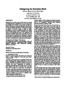
Stuck-at and stuck-open fault models are used to describe the effects of the majority of fabrication faults in CMOS circuits [9-11]. The stuck-at fault model assumes that a fabrication failure causes the wire to be stuck permanently at a certain logical value. Consider a fragment of a CMOS design (in Figure 1a) with possible locations of line stuckat faults. For instance, the stuck-at one fault in node 1(1-SA1) is interpreted as a break on line 1 with the gate of n-type transistor N2 connected permanently to the power supply voltage (in Figure 1b). The application of a constant voltage is marked with a cross. Fault 2-SA can be represented in three ways: • the disconnection of transistor N1 from node 2 and setting its source to a logical value (fault 2’-SA in Figure 1b); • the disconnection of transistor N3 from node 2 and setting its source to a logical value (fault 2’’-SA in Figure 1c); • the disconnection of transistor N2 from node 2 and setting its drain to a logical value (fault 2’’’-SA in Figure 1d).
4
N1
N1 N4
N3
1
2’
N3
N4
3
2
3’
1
N2
N2
a)
b)
N1
N1
N3
N4
N3
3’’
2’’
N4
2’’’
N2
N2
c)
d)
Fig. 1 : Locations of line stuck-at faults and their interpretation in a fragment of CMOS design Note that fault 2’’’-SA is equivalent to fault 1-SA0 when transistor N2 is permanently off. Thus, fault 2’’’-SA can be excluded for the sake of simplicity. Notations 3’-SA or 3’’-SA denote a break on the left side of line 3 and setting a permanent logical value on its right side or a break on the right side of line 3 and setting a permanent logical value on its left side respectively (compare Figures 1b and 1c). The basic CMOS inverter shown in Figure 2a consists of two types of transistors: p-type and n-type transistors [9]. When input x is low the n transistor is off and the p transistor is on. Output y is connected to the power supply voltage (Vdd) which corresponds to a logical one. If input x is high the n transistor is on and the p transistor is off. Output y is connected to ground (Vss) which is a logical zero. Figure 2a shows line stuck-at fault locations in the CMOS inverter. For example, fault 1-SA1 of the inverter sets its output y to a constant logical zero. Input x of the inverter must be set to low to detect this fault, whereupon output y remains low whereas the fault-free response is high.
tp 2
x
P1 6 4
P1 4
1
1
x
y
8 5
3
P2
2
N1
y
N2 7
tn
3
N1
b)
a)
Fig. 2 : CMOS inverters: a) inverter with two logically untestable stuck-at faults; b) testable inverter
5
Table 1 : Tests for stuck-at and stuck-open faults of the inverter in Figure 2b Single SA0 faults
Single SA1 faults
Single SO faults
2 8
8 2 1,4
P1,P2
3,5
N1,N2
4 5 1
6
7
3
6 7
x 1 0 1 0 0 1 1 1 0 0 1 0 0 1 1 0 0 1
Test sequences tn tp 1 0 1 0 1 0 1 0 1 0 1 0 1 1 0 0 0 0 1 1 1 1 1 1 0 0 0 0 1 0 1 0 1 0 1 0
Fault-free output
Faulty output
y 0 1 0 1 1 0 0 0’ 1 1’ 0 0’ 1 1’ 0 1 1 0
y 1 0 0 0’ 1 1’ 0 1 1 0 0 1 1 0 0 0w 1 1w
Consider fault 2-SA0 in the inverter illustrated in Figure 2a. This fault sets transistor P1 permanently on. If input x is high both transistors P1 and N1 are on. This leads to an uncertain situation when a logical one or zero can be registered by the test circuitry depending on the strengths of the transistors. As a consequence, the detection of fault 2SA0 cannot be guaranteed by logic testing. Similar observations can be made for fault 3-SA1. A stuck-open fault model represents a fault effect caused by a fabrication failure which permanently disconnects the transistor pin from the circuit node. Stuck-open faults can be opens on the gates, sources or drains of transistors. In the presence of a single stuckopen fault (SO) there is no path from the output of the circuit to either Vdd or Vss through the faulty transistor. For example, in the presence of fault P1-SO (Figure 2a) output y cannot be set high since there is no connection between Vdd and node y. This fault can be identified by a set of two test patterns applied sequentially to input x. As a result, the output of the faulty inverter remains low whereas the output of the faultfree inverter is high. Fault N1-SO is detectable by a test set . Figure 2b shows a CMOS inverter which is testable for all single stuck-at and stuckopen faults. Two additional transistors (P1 and N1) controlled by two separate inputs are inserted into the inverter shown in Figure 2a. Table 1 contains tests for line stuck-at faults and transistor stuck-open faults in the inverter. Note that faults 4-SA0 and 5-SA1
6
are detectable by logic testing. For instance, a test sequence applied to the inputs of the inverter detects fault 4-SA0. The effect of fault 6-SA0 or 7-SA1 is a ‘weak zero’ (0w) or a ‘weak one’ (1w) output signal respectively. These voltage levels are very close to the corresponding logical 1 and 0 voltage levels since output y was previously set to the same logical values. Faults 1-SA1 or 3-SA0 result in a ‘floating zero’ (0’) or ‘floating one’ (1’) output signal respectively. The output capacitance of the inverter can be considered as a dynamic memory element which keeps its precharged value for a certain time. It is assumed that the time between the application of two test vectors is small enough not to allow a floating output voltage level to reach the CMOS threshold level [9,11]. Hereafter we will treat weak and floating logical values as normal ones. A stuck-at fault on the gate of a CMOS transistor keeps the transistor on or off permanently depending of the type of fault. Thus transistor stuck-open faults in CMOS designs can be represented by their correspondent gate stuck-at faults. For instance, fault 5-SA0 on the gate of transistor N2 is equivalent to fault N2-SO (see Figure 2b). As a result, testing for stuck-at faults of the inverter illustrated in Figure 2b guarantees the detection of all its stuck-open faults.
3
Symmetric C-element CMOS designs
Figure 3a shows a symbolic representation of the two-input symmetric C-element with inputs a, b and output c. The symmetric C-element is a state holding element the output of which is high when its inputs are high and low when its inputs are low. Any other input combinations do not change the state of the C-element. The function performed by the two-input symmetric C-element can be written as follows: ct = at ⋅ bt + at ⋅ ct – 1 + bt ⋅ ct – 1
,
(1)
where ct and ct-1 are the states of the C-element at time t and t-1 respectively. There are different ways to implement static symmetric C-elements in CMOS technology. Figure 3b shows a CMOS C-element which performs according to equation 1. For example, when a=1 and b=1 there is a path between Vss and the input of inverter inv. As a result, output c of the C-element is high and feedback n-type transistor N5 is on. If the inputs of the C-element are different there is always a connection between Vss and the input of inverter inv. Equation 1 can be rewritten in the following form: ct = ( at + bt) ⋅ ct – 1 + at ⋅ bt
.
(2)
A CMOS implementation of the symmetric C-element which performs according to equation 2 is illustrated in Figure 3c. This C-element works in a similar way as the one shown in Figure 3b. Both CMOS implementations of the symmetric C-element require 12 transistors. The symmetric C-element shown in Figure 3d is a pseudo-static C-element which performs according to equation 1 but in a way similar to that of a dynamic C-element. The only difference is that the weak feedback inverter inv2 is inserted into the symmetric C-
7
element to create a CMOS memory. If ct-1=0, at=1 and bt=1 then the input of inverter inv1 is driven to low since the strength of n-type input stack (transistors N1 and N2) is higher than that of p-type stack of weak inverter inv2. As a consequence, output c of the C-element goes high keeping the input of inverter inv1 in low. If the input transistor stacks are disabled by different input signals the current state of the C-element is kept unchanged. The implementation of the pseudo-static C-element requires 8 transistors. For test purposes we assume that the inputs of the C-element are controllable and its outputs are observable. It has already been shown in Section 2 that some of single stuckat faults in the CMOS inverter are not detectable by logic testing. Therefore, such faults are not detectable in the CMOS designs depicted in Figure 3. There is a fundamental problem in the testing of static C-elements for stuck-open faults. Stuck-open faults in the feedback transistors of the static symmetric C-element transform it into a dynamic one. For instance, if the output of the weak inverter in the C-element shown in Figure 3d is disconnected from the input of inverter inv1 the faulty C-element still performs according to equation 1, but as a dynamic circuit. This kind of fault can be identified only by ‘slow’ testing which ‘waits’ until the output of the faulty C-element is discharged completely. This degrades the test performance. CMOS structures of the symmetric C-element which provide for detection of single line stuck-at and transistor stuck-open faults are considered in the following sections.
a b
C
a
P1
b
P2
a
N1
P5
P3
b
P4
a
N3
b
N4
a
c
c
a) b
N5
N2
inv
b) a b
P1
a
N1
b
N2
b inv
P1
b
P2
a
N1
N3 N4
b
N2
inv2
c
c
N5
a
a
wk
P5
P2
a
P3 P4
b
c)
inv1
d)
Fig. 3 : Symmetric C-elements: a) symbol of the two-input C-element; b) and c) static C-elements; d) pseudo-static C-element
8
a
P1
P3
b
P7 N7
c
P5
b
P2
P4
a
a
N1
N3
b
N4
a
wk
P6
N5
b
N2
N6 wk
m Fig. 4 : Locations of stuck-open faults in the static symmetric C-element
4
Testing for stuck-open faults
The testing of stuck-open faults in the feedback transistors of the static symmetric Celement is implemented by driving them using an extra input and observing test results on its output. The structure shown in Figure 3b is most suitable as the starting point for the testable implementation. Figure 4 illustrates a CMOS design of the symmetric Celement where single transistor stuck-open faults are detectable. The C-element contains an additional weak inverter (transistors P6 and N6) the output of which can be overdriven by a logical value applied to pin m. The proposed implementation of the symmetric C-element requires 14 transistors. Table 2 : Tests for stuck-open faults of the symmetric C-element in Figure 4
Stuck-open faults P2,P3,P5,N7 P1,P4,P5,N7 N2,N3,N5,P7 N1,N4,N5,P7 P6 N6
Test sequences a 1 1 1 0 0 0 0 1 0 1 1 0
b 1 0 1 1 0 1 0 0 0 1 1 0
mi 0 0 0 0 1 1 1 1 z z z z
9
Outputs of the fault-free Celement c mo 1 0 1 0 0 1 0 1 0 0 1 1 1 1 0 0
Outputs of the faulty C-element c mo 1 1 1 1 0 0 0 0 0 0 1 0 1 1 0 1
Tests for the transistor stuck-open faults of the C-element are shown in Table 2. If mi=0 or mi=1 node m is used to drive feedback transistors P5 and N5 with a logical zero or one respectively. If mi=z then node m is in a high impedance mode. A hyphen in the column headed mo means that node m does not carry any diagnostic information since it is driven by an external logical value. It can be seen from Table 2 that faults P5-SO and N5-SO, which transform the static behaviour of the symmetric C-element into a dynamic one, are detectable by sets of two tests with no need for ‘slow’ testing. Driving the feedback transistors of the symmetric C-element transforms its sequential function into a combinational one depending on the logical value applied to pin m. Table 3 contains the operation modes of the symmetric C-element illustrated in Figure 4. When mi=0 or mi=1 the C-element is transformed into an AND or OR gate respectively. This transformation of the sequential function of the C-element allows a reduction in the number of state holding elements in the asynchronous circuit under test and makes its testing easier. On the other hand, once the circuit (in Figure 4) performs as the symmetric C-element output m can be used as a test point increasing its observability inside the asynchronous circuit. The use of a weak inverter in the symmetric C-element illustrated in Figure 4 is not efficient in terms of power consumption in test mode. For instance, if during the test pin m is kept to one and a=b=0 then there is a path between Vdd and Vss which increases the power dissipation of the C-element. The power consumption can be reduced if the weak inverter is replaced by a tristate inverter which is disabled during the test by an extra control input. It is easy to show that in this case such a C-element remains testable for transistor stuck-open faults.
Table 3 : Operation modes of the C-element in Figure 4
Function
AND
OR
Symmetric Muller C
a 0 0 1 1 0 0 1 1 0 0 1 1
Inputs b 0 1 0 1 0 1 0 1 0 1 0 1
10
mi 0 0 0 0 1 1 1 1 z z z z
Outputs ct mo 0 0 0 1 0 1 1 1 0 0 ct-1 ct-1 ct-1 ct-1 1 1
5
Testing for stuck-at faults
The symmetric C-element illustrated in Figure 4 is not testable for line stuck-at faults since it has inverters which are not fully testable for all single line stuck-at faults (see Section 2). The implementation of the symmetric C-element shown in Figure 5 incorporates inverters which are testable for single stuck-at faults using two additional test inputs tp and tn. Two extra transistors controlled by inputs tp and tn are inserted in the feedback paths of the C-element for testability purposes. In normal operation mode, when tp=0 and tn=1 the circuit performs in the same manner as the one in Figure 4. It is assumed that all the inputs and outputs of the C-element are controllable and observable during the test. Table 4 contains tests which are derived to detect its single line stuck-at faults. As was observed previously in Section 2 the detection of all single line stuck-at faults in a CMOS design guarantees the detection of all its single stuck-open faults. For instance, fault 18-SA1 is equivalent to keeping the appropriate p-type transistor off permanently which means its permanent disconnection from Vdd. As a result, the proposed CMOS design is testable for both stuck-at and stuck-open faults.
tp
35
a
1
33
3
10 7
b
2
14 12
18
b
23
19
a
24
16
21
tn
31
32
a
25
b
26
17
wk
22
15
wk
c
29 41
39
6 11
40 28
wk
20
8 5 13
27
38
4
9
37
wk
30
m
36 34
Fig. 5 : Locations of stuck-at faults in the static C-element
11
Table 4 : Tests for stuck-at faults of the C-element in Figure 4
No
Single stuck-0 faults
1 2 3
31,32,38,40 8,20,37 7’,12’,16’,30
4
7’’,12’’,16’’
5
2,5,9’’,11,13’’, 15,22 1,6,11,13’,15, 17’,21 25,26,29,30, 34,36
6 7 8
Single stuck-1 faults
8,20,37 31,32,39,41 2,4,7’’,10,12’’, 14,18 1,3,10,14,12’, 16’,19 9’,13’,17’,27 9’’,13’’,17’’
9
4,10,18
23,24,27,28, 33,35 16’’
10
3,10,19
7’
11
17’’
5,11,22
12
9’
6,11,21
13
14
14
15
15
23,27,33,35
38,40
16
39,41
26,30,34,36
17
24,28
18
25,29
mi
Outputs of the fault free circuit c mo
Outputs of the faulty circuit c mo
z z 0 0 0 0 1 1 1 1 z z z z 0 0 0 0 1 1 1 1 1 1 0 0 0 1 z z z z z z z z
1 0 1 0 1 0 0 1 0 1 1 0 0 1 1 1 1 1 0 0 0 0 1 1 1 0 0 0 0 0 1 1 0 0 1 1
0 1 1 1 1 1 0 0 0 0 1 1 0 0 1 0 1 0 0 1 0 1 1 1 0 0 0 1 0 1 1 0 0 1 1 0
Test sequences a& b 11 00 11 10 11 01 00 01 00 10 11 00 00 11 11 01 11 10 00 10 00 01 11 10 10 00 10 10 00 11 11 00 00 00 11 11
12
t& tp 10 10 10 10 10 10 10 10 10 10 10 10 10 10 10 11 10 11 10 00 10 00 00 00 11 11 11 00 10 11 10 00 11 00 00 11
1 0 1 0 0 1 0 0 1 1 0 0 1 1
0 1 1 1 0 0 0 1 1 0 0 1 1 0
6
Static asymmetric C-elements
So-called asymmetric C-elements are used widely to improve the performance of the asynchronous control logic in micropipelines [8,12]. These C-elements are set to a particular state when both signals are one or zero and set to the negated state only by one input. Figures 6a and 6b demonstrate a symbolic representation and a gate level implementation of the OR-AND type asymmetric C-element. The OR-AND type asymmetric C-element performs according to the following equation: ct = a ⋅ ( b + ct – 1)
.
(3)
The output of such an asymmetric C-element is set to high when both its inputs are high and set to low if its input a is low. It keeps its current state when its input a is high and input b is low. A static CMOS implementation of the OR-AND type asymmetric C-element is illustrated in Figure 6c. Figures 7a and 7b show a symbolic representation and a gate level implementation of the AND-OR type asymmetric C-element. This C-element performs according to the following equation: ct = b + a ⋅ ct – 1
a b
C
.
(4)
c
c
b
+
a
a)
b)
P1
a b
P3 P4
P2
c N2
N1
N4
N3
c) Fig. 6 : Static OR-AND type asymmetric C-element: a) symbol; b) gate level representation; c) CMOS implementation
13
a b
C
c a
c
-
b
a)
b)
b
P2 P1
P4
P3
c a
N1 N3
N4
N2
c) Fig. 7 : Static AND-OR type asymmetric C-element: a) symbol; b) gate level representation; c) CMOS implementation
The output of the AND-OR type asymmetric C-element is set to high if its input b is high and set to low when both its inputs are low. It preserves its current state when input a is high and input b is low. A static CMOS implementation of the AND-OR type asymmetric C-element is shown in Figure 7c. These two types of asymmetric C-elements were implemented in CMOS technology on a 1 µm , double layer metal CMOS process and simulated using SPICE analysis in Cadence CAD environment. Simulation results obtained from their extracted layouts can be found in Appendix. Testing for stuck-at and stuck-open faults in asymmetric C-elements is not easy. For instance, such stuck-open faults as N3-SO (in Figure 6c) and P3-SO (in Figure 7c) can be identified only by ‘slow’ testing since they transform the correspondent static asymmetric C-elements into dynamic ones. As it was previously mentioned a stuck-at-0 fault on the gate of transistor P4 and stuck-at-1 fault on the gate of transistor N4 of the asymmetric C-elements are not detectable by logic testing. Thus, extra design efforts must be involved to make the asymmetric C-elements testable.
7
Testing for stuck-open faults in asymmetric C-elements
Figures 8a and 8b illustrate the designs of asymmetric C-elements testable for transistor stuck-open faults. The main approach to testing of stuck-open faults in asymmetric C-
14
elements is the same: the feedback transistors are driven by external control input m making them controllable. For this purpose an additional weak inverter (transistors P4 and N4) is inserted into the original designs of asymmetric C-elements. Its output can be overdriven by applying a logical value to its output m. If no logical values are applied to output m then it can be used as a test point during the test.
P1
a b
P3
wk
P4
P2
P5
c N2
N4
N5
P4
P5
wk
N1
N3
m a)
b
P2 wk
P1
P3
c a
N1 N3
m
N4
N5
wk
N2
b)
Fig. 8 : Static asymmetric C-elements testable for stuck-open faults: a) OR-AND type asymmetric C-element; b) AND-OR type asymmetric C-element
15
Table 5 : Tests for stuck-open faults of the OR-AND type asymmetric C-element
Stuck-open faults P1,P2,N5 N1,N2,P5 N3 P4 P3,N4
Test sequences a 1 1 0 1 0 1 0 1 1 0
b 1 0 1 1 0 0 1 1 1 1
mi 0 0 0 0 1 1 z z z z
Outputs of the fault-free Celement c mo 1 0 0 1 0 1 0 0 1 1 1 1 0 0
Outputs of the faulty C-element c mo 1 1 0 0 0 0 0 0 1 0 1 1 1 1
Table 6 : Tests for stuck-open faults of the AND-OR type asymmetric C-element
Stuck-open faults P1,P2,N5 P3 N1,N2,P5 N3,P4 N4
Test sequences a 1 0 1 1 0 1 0 0 0 0
b 0 0 1 0 0 0 0 1 1 0
mi 1 1 0 0 1 1 z z z z
Outputs of the fault-free Celement c mo 1 0 1 0 0 1 0 0 1 1 1 1 0 0
Outputs of the faulty C-element c mo 1 1 1 1 0 0 0 0 0 0 1 1 0 1
Tests for the transistor stuck-open faults of the asymmetric C-elements (in Figure 8) are shown in Tables 6 and 7. Denotations of these tables have the same meanings as the ones used in Table 2. As it follows from Tables 6 and 7 all stuck-open faults of the asymmetric C-elements are detectable by only five tests which include two sequential tests each.
16
Table 7 : Operation modes of asymmetric C-elements shown in Figure 8 Function of OR-AND type C-element
Function of AND-OR type C-element
AND
B-repeater
A-repeater
OR
OR-AND type asymmetric Celement
AND-OR type asymmetric Celement
Inputs a 0 0 1 1 0 0 1 1 0 0 1 1
b 0 1 0 1 0 1 0 1 0 1 0 1
mi 0 0 0 0 1 1 1 1 z z z z
Outputs of OR-AND type C-element ct mo 0 0 0 1 0 0 1 1 0 0 0 0 ct-1 ct-1 1 1
Outputs of AND-OR type C-element ct mo 0 1 0 1 0 1 1 1 0 0 1 1 ct-1 ct-1 1 1
The designs of asymmetric C-elements testable for transistor stuck-open faults were implemented on a 1 µm , double layer metal CMOS process and simulated using SPICE analysis in Cadence CAD environment. Simulation results obtained from their extracted layouts can be found in Appendix. Driving the feedback transistors allows the sequential functions of the asymmetric Celements to be changed into combinational ones. Table 7 shows the operation modes of the C-elements illustrated in Figure 8. If output m of the OR-AND type asymmetric Celement is driven by a logical zero or one then its function is transformed into an AND gate or a repeater of its input a respectively. When output m of the AND-OR type asymmetric C-element is overdriven by a logical one or zero its sequential function is transformed into an OR gate or a repeater of its input b respectively. These properties of the asymmetric C-elements (in Figure 8) can be used to simplify the testing of asynchronous circuits by reducing the number of their state holding elements.
8
Testing for stuck-at faults in asymmetric C-elements
As was mentioned previously the stuck-open testability of CMOS circuits does not guarantee the detection of all their line stuck-at faults. In order to make the asymmetric C-elements illustrated in Figure 8 testable for line stuck-at faults two additional inputs tp and tn are required. Figure 9 shows a CMOS implementation of the static OR-AND type asymmetric C-element testable for stuck-at faults. In normal operation mode inputs tp and tn are set to zero and one respectively and the circuit exhibits the same behaviour as the one demonstrated in Figure 8a.
17
P4
1
tp
9
8 25
b
4
P6
10
P1 11
3
2
27
a
12
13
P3
P2
30
wk
N2
23
29
N5
16
wk 5
21
N1
tn
6
m
20
c
N6 31
N3 18
17
P7 32
26
15 14
28
P5
22
N7
19 7
N4 24
Fig. 9 : Static OR-AND type asymmetric C-element testable for stuck-at faults Table 8 contains tests to detect the single line stuck-at faults whose locations are shown in Figure 9. It is presumed that all the inputs and outputs of the asymmetric C-element are controllable and observable during the test. The C-element illustrated in Figure 9 is testable for its stuck-open faults since it is fully testable for its stuck-at faults. The asymmetric C-element testable for single line stuck-at faults was implemented on a 1 µm , double layer metal CMOS process and simulated using SPICE analysis. Simulation results obtained from its extracted layout can be found in Appendix.
Table 8 : Tests for stuck-at faults of the asymmetric C-element in Figure 9
No
Single stuck-0 faults
Single stuck-1 faults 15,27
2
9,20,24,26 ,30,32 15,27
3
7,23,29
19,20,24,2 6,31, 32 1
4
6
2,22,28
1
Test sequences
Outputs of the faultfree circuit c mo
Outputs of the faulty circuit c mo
a& b 11
tp& tn 01
mi z
1
1
0
0
00
01
z
0
0
1
1
11 01 01 11
01 01 01 01
z z z z
1 0 0 1
1 0 0 1
1 1 0 0
1 1 0 0
18
Table 8 : Tests for stuck-at faults of the asymmetric C-element in Figure 9
No
Single stuck-0 faults
Single stuck-1 faults
5
3,4,25
6
12,13
7
3,5
8
12,14,21
9
1
10
2
11
6
12
7
13
22,28
14
23,29
15
25
16
4,13
17
14
18
5,21
19
8,10,11
20
9,30
Test sequences a& b 11 10 1x 0x 01 11 00 10 11 01 01 11 00 10 11 01 00 00 00 11 11 11 11 10 00 11 11 01 00 00 10 00 10 11 11 00 01 11
tp& tn 01 01 01 01 01 01 01 01 11 11 01 11 01 00 01 00 01 11 00 01 00 11 01 00 11 01 00 11 01 11 00 01 11 00 01 11 01 11
19
mi 0 0 1 1 0 0 1 1 0 0 0 0 1 1 1 1 z z z z z z 1 1 1 0 0 0 1 1 1 0 0 0 0 0 z z
Outputs of the faultfree circuit c mo 1 0 1 0 0 1 0 1 1 1 0 0 0 0 1 1 0 0 0 1 1 1 1 1 1 1 1 1 0 0 0 0 0 0 1 1 0 0
0 0 0 1 1 1 0 0
Outputs of the faulty circuit c mo 1 1 1 1 0 0 0 0 1 0 0 1 0 1 1 0 x 0 1 x 1 0 1 1 0 1 1 0 0 0 1 0 0 1 1 0 0 1
x 0 1 x 1 0 0 1
Table 8 : Tests for stuck-at faults of the asymmetric C-element in Figure 9
No
9
Single stuck-0 faults
21
8,11
22 23
10 19,31
24
16,17,18
Single stuck-1 faults
25
17
26
16,18
Test sequences a& b 01 10 01 11 01 01 11 01 11 10
tp& tn 01 01 01 01 00 01 00 01 01 01
mi 0 0 1 z z 1 1 z z 1
Outputs of the faultfree circuit c mo 0 0 0 1 1 0 0 0 1 1
1 1 0 1 -
Outputs of the faulty circuit c mo 0 1 1 1 0 0 1 0 0 0
1 0 0 0 -
Scan testing of C-elements
Scan testing has already become a standard methodology for testing VLSI circuits [13]. Several attempts to implement a scan test in asynchronous circuits have been published [14-16]. Scan testing presumes that the circuit is set to scan test mode where all its state holding elements are connected together forming a united scan chain. The scan path can be controlled either synchronously or asynchronously [16]. As a consequence, the states of all memory elements are controllable and observable. State holding elements of a scan testable circuit must operate at least in two modes: normal and scan test modes. In normal operation mode, the circuit performs according to its specification. During the scan test, the test patterns are loaded into the state holding elements and the test results are shifted out of the circuit. Figure 10 illustrates a CMOS implementation of the pseudo-static symmetric C-element with scan features. It contains two additional control inputs: clock (Clk) and scan test (T) signals. Inputs Sin and Sout are used to scan the test pattern in and scan the state bit out of the C-element. Output Sout of each scan testable C-element (or any other scan testable memory block) is connected to input Sin of its successor forming the scan chain. In normal operation mode, when T=0 and Clk=0 the C-element performs as the pseudostatic C-element depicted in Figure 3d. In scan mode, the input transistor stack is disabled by input T set to high. Clock signals are generated on input Clk to shift the test pattern from input Sin into the C-element. When signal Clk goes high the output transistor stack of the C-element is disabled and nodes c and nc are controlled from input Sin. Once the clock signal is low the negated bit loaded from input Sin is stored in the C-element and is passed to its output Sout. Clock signals generated on input Clk are used to shift the state bit of the C-element through the scan path to the test circuitry. When Clk=1 output Sout keeps its current logical value creating a dynamic memory and
20
Clk
P7 P8
Sout T
P1
a
P2
b
P3
a
N1
N7
Clk
nClk
P5
N8
wk
nc
P4
P6
N4
N5
c wk
b
N2
nT
N3
nClk
nClk
N6
P9 P10
Sin
N9
Clk P11
nClk
Clk
N10
P12
nT
T N12
N11
Fig. 10 : Pseudo-static symmetric C-element with scan features supplying input Sin of the following memory element. Clock signals must be kept high for enough time to guarantee the proper transmission of logical voltage levels. An analysis of the symmetric C-element shown in Figure 10 reveals that it is testable for single transistor stuck-open faults. Table 9 contains tests for detecting stuck-open faults of the C-element. Symbol ‘x’ denotes a ‘don’t care’ signal. A hyphen means that the appropriate output is not used to observe the test results. Note that the fundamental problem of testing stuck-open faults in the weak feedback inverter of the pseudo-static C-element no longer exists since the weak transistors of the scan testable C-element participate in the scanning of the test data. Consider an implementation of the scan testable CALL element in order to demonstrate how the C-element shown in Figure 10 can be used to build more complex scan testable asynchronous blocks. The CALL element is an event driven logic block [17]. It remembers which of its inputs received an event first (R1 or R2) and acknowledges the completion of the called procedure by an appropriate event on the matching output (D1 or
21
D2). The CALL element with scan features shown in Figure 11 performs using the twophase signalling protocol where each signal transition denotes an event. All the inputs and outputs are initialized to zero. T=0 and Clk=0 in normal operation mode. When a rising request signal is generated on input Ri it primes C-element Ci and passes through the XOR gate producing a rising request signal on its output R. Once the required procedure completed an appropriate acknowledge event is generated on input D. As a result, C-element Ci is set to one and a rising acknowledge signal is passed to output Di (i=1,2). The performance of the CALL element is identical for falling request events. If the CALL element shown in Figure 11 is incorporated into an asynchronous VLSI circuit its internal states can be controllable and observable through the scan path. A test bit sent to input Sin of the C-element is negated on its outputs Sout and c (see Figure 10). The CALL element is tested by setting test control signal T to one. For instance, the clocked sequence 01 must be applied to input Sin of the CALL element in order to set its C-elements to one. The CALL element can perform its specified function when signals T and Clk are returned to zero. The state bits of the C-elements are shifted out of the CALL element and compared with known responses when its input T is set one and clocks are produced on its input Clk.
Table 9 : Tests for stuck-open faults of the C-element in Figure 6
Single stuck-open faults P1-P3,N5,N6 P5,P6,P12,N1-N3 P7-P10,N4,N11
P4,P11,N7-N10
N12
Test sequences a& b 11 00 00 11 xx xx xx xx xx xx xx xx 00 11
T
Clk
Sin
0 0 0 0 1 1 1 1 1 1 1 1 0 1
0 0 0 0 1 0 1 0 1 0 1 0 0 0
x x x x 1 1 0 0 0 0 1 1 x x
22
Outputs of the fault-free Celement c Sout 1 0 0 1 0 0
x 0 1 1 x 1 0 0 0 0
Outputs of the faulty C-element c Sout 1 1 0 0 0 1
x 0 0 0 x 1 1 1 0 1
R1 Sout T Sout
D
C1
D1
Clk Sin
R
Clk
Clk Sout
C2 T
D2
Sin
T Sin R2
Fig. 11 : CALL element with scan features
10
Cost comparisons
The testable structures of the symmetric and asymmetric C-elements presented in this report require different overheads depending on the fabrication faults to be detected. The designs of testable C-elements have been implemented on a 1 µm CMOS process and their extracted layouts have been investigated using SPICE analyses. Table 10 contains a summary of cost implementation comparisons of the CMOS C-elements and their testability. The largest number of transistors is required to implement the scan testable C-element. This is because scanning the data through the C-element can be implemented only in a master-slave manner which requires at least two memory elements. The implementation of the symmetric C-element shown in Figure 3 has just 17% layout overhead with one extra control input and guarantees the detection of all its stuck-open faults. The sequential function of such a C-element can be changed into a combinational one (AND or OR) which simplifies the testing of other components incorporated in the asynchronous circuit. The asymmetric testable C-elements illustrated in Figure 8a and 8b guarantee the detection of all their transistor stuck-open faults and require 19% and 32% layout overheads respectively.
23
Table 10 : Summary Design
Figure 3 Figure 4
14 20
No. of extra inputs/ outputs 1 3
Figure 8a Figure 8b Figure 9
10 10 14
1 1 3
25% 25% 75%
19% 32% 41%
2.45 2.55 2.18
Figure 10
24
4
200%
115%
11.22
11
No. of transistors
of costs of the testable C-elements Transistor overhead
Layout overhead
Output nodal capacitance
17% 67%
17% 45%
2.07 3.21
× 10
– 14
F
Testability SO SA& SO SO SO SA& SO SO
Conclusions
CMOS C-element designs for testability have been presented. Tests for detection of all single line stuck-at and transistor stuck-open faults of the proposed testable implementations of the symmetric and asymmetric C-elements have been derived. It has been shown that although the CMOS C-element testable for line stuck-at faults allows the detection of all its single stuck-open faults its implementation requires more overhead than that of the C-element testable only for stuck-open faults. The fundamental problem of testing feedback transistors in static C-elements has been resolved. We illustrated that the sequential function of the symmetric C-element can be transformed into a combinational one (AND or OR) by driving its feedback transistors with an additional input. The asymmetric C-elements can be transformed into repeaters of one of their inputs, OR or AND gates. A scan test can be implemented by using the scan testable C-element design described in the report. An analysis of the costs required to implement different testable C-element structures has been presented. It shows that the largest number of transistors and area overhead are required to implement the scan testable C-element. The CMOS structures of the C-element considered in the report can be used to design asynchronous VLSI circuits for testability.
Acknowledgments We would like to express our gratitude to Jim Garside and David Jackson for their useful comments and discussions on the topic of this report. Special thanks to Craig Farnsworth for his invaluable help and consultation with Cadence CAD tools.
24
References [1] S. Hauck, “Asynchronous design methodologies: An overview,” Proc. IEEE, Vol. 83, No. 1, Jan. 1995, pp. 69-93. [2] L. Lavagno, A. Sangiovanni-Vincentelli, “Algorithms for synthesis and testing of asynchronous circuits,” Kluwer Academic Publishers, 1993. [3] S. B. Furber, P. Day, J. D. Garside, N. C. Paver, J. V. Woods, “AMULET1: A micropipelined ARM,” Proc. IEEE Comput. Conf., March 1994. [4] H. Hulgaard, S. M. Burns, G. Borriello, “Testing asynchronous circuits: A survey,” TR-FR35, Department of Computer Science, University of Washington, Seattle, WA, USA, 1994. [5] P. Hazewindus, “Testing delay-insensitive circuits,” Ph.D. thesis, Caltech-CS-TR-92-14, California Institute of Technology, 1992. [6] P. A. Beerel, T. H. Y. Meng, “Semi-modularity and testability of speed-independent circuits,” Integration, The VLSI Journal, 13, 1992, pp. 301-322. [7] I. David, R. Ginosar, M. Yoeli, “Self-timed is self-diagnostic,” TR-UT-84112, Department of Computer Science, University of Utah, Salt Lake City, UT, USA, 1990. [8] J. A. Brzozowski, K. Raahemifar, “Testing C-elements is not elementary,” Proc. 2nd Working Conf. on Asynchronous Design Methodologies, South Bank University, May 30-31 1995, pp. 150-159. [9] N. H. E. Weste, K. Eshraghian, “Principles of CMOS VLSI design: A systems perspective,” Addison-Wesley Publishing Co., 1993. [10] R. L. Wadsack, “Fault modelling and logic simulation of CMOS and MOS circuits,” Bell System Tech. Journal, vol. 57, May-June 1978, pp. 1449-1474. [11] M. K. Reddy, S. M. Reddy, “Detecting FET stuck-open faults in CMOS latches and flipflops,” IEEE Design & Test of Computers, vol. 3, no. 5, Oct. 1986, pp. 17-26. [12] C. Farnsworth, D. A. Edwards, Jianwei Liu, S. S. Sikand, “A hybrid asynchronous system design environment,” Proc. 2nd Working Conf. on Asynchronous Design Methodologies, South Bank University, May 30-31 1995, pp. 91-98. [13] G. Russell, I. L. Sayers, “Advanced simulation and test methodologies for VLSI design,” Van Nostrand Reinhold (International), 1989. [14] M. Roncken, “Partial scan test for asynchronous circuits illustrated on a DCC error corrector,” in Proc. Int. Symposium on Advanced Research in Asynchronous Circuits and Systems (Async94), Nov. 1994, pp. 247-256. [15] A. Khoche, E. Brunvand, “Testing micropipelines,” Proc. Int. Symposium on Advanced Research in Asynchronous Circuits and Systems (Async94), Utah, Nov. 1994, pp. 239246. [16] O.A.Petlin, S.Furber, “Scan testing of micropipelines”, Proc. 13th IEEE VLSI Test Symposium, Princeton, New Jersey, USA, May 1995, pp. 296-301. [17] I. E. Sutherland, “Micropipelines,” Communications of the ACM, Vol.32, no.6, June 1989, pp. 720-738.
25
Appendix:
C-element cells
26
Library "olegs": MullerC2_stat
Symbolic
Load Information
Area in microns squared = 27.500 * 47.5
27
!Format Type= Olod= Part= Load 3.48916e-14 'a' Load 3.84306e-14 'b' Load 4.5572e-14 'c' Load 1.23073e-13 '6'
Library "olegs": tst_C2
Symbolic
Load Information
Area in microns squared = 32.250 * 47.5
28
!Format Type= Olod= Part= Load 3.47469e-14 'a' Load 4.41205e-14 'b' Load 2.0685e-14 'c' Load 6.37769e-14 'm' Load 2.20468e-13 '7'
Library "olegs": tst_safC2
Symbolic
Load Information
Area in microns squared = 39.750 * 47.5
29
!Format Type= Olod= Part= Load 3.43293e-14 'a' Load 3.63979e-14 'b' Load 2.6494e-14 'tn' Load 2.94618e-14 'tp' Load 2.53265e-13 '5' Load 7.54418e-14 'm' Load 4.6622e-14 'c'
Library "olegs": tst_stat_asyC2_nb
Symbolic
Load Information
Area in microns squared = 24.000 * 47.5
30
!Format Type= Olod= Part= Load 1.92116e-14 'A' Load 1.76288e-14 'B' Load 2.14553e-14 'C' Load 6.6082e-14 'Y' Load 1.72007e-13 '3'
Library "olegs": tst_stat_asyC2_pb
Symbolic
Load Information
Area in microns squared = 26.500 * 47.5
31
!Format Type= Olod= Part= Load 1.96295e-14 'A' Load 1.6364e-14 'B' Load 7.45002e-14 'Y' Load 2.54551e-14 'C' Load 2.1555e-13 '3'
Library "olegs": tst_saf_asyC2_nb
Symbolic
Load Information
Area in microns squared = 28.500 * 47.5
32
!Format Type= Olod= Part= Load 1.91955e-14 'A' Load 1.86423e-14 'B' Load 2.41143e-14 'Tn' Load 2.20991e-14 'Tp' Load 1.33867e-13 'Y' Load 3.67942e-14 'C'
Library "olegs": tst_scanC2
Symbolic
Load Information
Area in microns squared = 50.500 * 47.5
33
!Format Type= Olod= Part= Load 5.73717e-14 'Clk' Load 1.70802e-14 'Sin' Load 3.64919e-14 'T' Load 1.67269e-14 'a' Load 1.70992e-14 'b' Load 6.40658e-14 '9' Load 3.75031e-14 '15' Load 1.14159e-13 'data' Load 1.31744e-13 'c' Load 4.72416e-14 'Sout'