the declarative representation of design aspects involved in the MIS (Mixed Interaction Space) design. The design aspects of MIS are related to the spatial and ...
'HVLJQLQJ�,QWHUDFWLRQ�6SDFH�IRU�0L[HG�5HDOLW\�6\VWHPV� � �
�
'DQLHOD�7UHYLVDQ ��-HDQ�9DQGHUGRQFNW ��%HQRvW�0DFT � Catholic University of Louvain 1 2 Information Systems Unit, School of Communications and Remote Sensing Lab. Management, Place des Doyens, 1 Bâtiment Stévin, Place du Levant, 2 +32 10 478525 +32 10 478555 {trevisan,vanderdonckt}@isys.ucl.ac.be {trevisan, macq}@tele.ucl.ac.be
��������
�
A mixed scenario involves a lot of objects which may be related in various ways. These relations may lead to inconsistencies similar to those related to continuous interaction. We propose here a model for the declarative representation of the design aspects involved in a MIS (Mixed Interaction Space).
which each virtual object is registered to a (tangible) physical object and the user interacts with a virtual object by manipulating the corresponding tangible (physical) object. The development and implementation of such systems becomes very complex and support guidance during design of conventional interfaces is not anymore valid for modeling this class of systems.
� ���
User-interface design, mixed interaction space, spatial integration, temporal integration, mixed reality systems.
By definition [11] an interaction space may entail� the representation of the visual, haptic and auditory elements that a user interface offers to its users. The interaction space for mixed reality systems should deal with elements which come from real and virtual world. It entails the design of a mixed interaction space.
������������
Mixed Reality (MR) is the state-of-the-art technology that merges the real and virtual worlds seamlessly in real time. It draws attention as a new technology of human interface, which surpasses the border that the conventional virtual reality has.
For addressing these questions we present here a model for the declarative representation of design aspects involved in the MIS (Mixed Interaction Space) design. The design aspects of MIS are related to the spatial and temporal relationships between objects, user’s interaction focus and insertion context of interaction spaces. They can facilitate or prevent the task goals from being attained, limiting interaction performance. Then an interaction space supporting these design characteristics could be very useful to guarantee a seamless interaction in the MR system.
In view of the multidisciplinary integration and associated complexity existing in MR systems, the reality paradigm given by [4], proposes taxonomy where Real Environments (RE) and Virtual Environments (VE) are, in fact, two poles of the Reality-Virtuality Continuum, RE being the left pole and VE, the right pole. Mixed Reality includes the continuum transitions from RE, to Augmented Reality (AR), passing through Augmented Virtuality (AV) and towards VE, but excludes the end-points, perceived as limit conditions. In both AV, in which real objects are added to virtual ones, and VE (or virtual reality), the surround environment is virtual while in AR the surround environment is real.
The interaction space description is based on the presentation model definition given in [11] and the model language is based on the spatio-temporal composition model given in [12]. As example of how uses the approach for designing Mixed Interaction Space we will take account the Image-guided surgery (IGS) interaction space scenario. In such systems complex surgical procedure can be navigated visually with great precision by overlaying on an image of the patient a color coded preoperative plan specifying details such as the locations of incisions, areas to be avoided and the diseased tissue. It is a typical application of augmented reality (AR) systems where the virtual world corresponding to the preoperative information should be correctly aligned in real time with the real world corresponding to the intraoperative information. This study case was thoroughly discussed by the authors in [9].
The user’s interaction with this Reality-Virtuality Continuum can be augmented by tangible interface. According to [6] and [8] tangible interfaces are those in
1
needed once the user can manipulate objects in the virtual world through the VIS or the user can manipulate objects in the real world through the RIS.
Note that the terms ‘digital’ and ‘virtual’ are used in this work in the sense of not physical or real. The terms “real” and “physical” are used in the sense of not digital or virtual.
&RQFUHWH� ,QWHUDFWLRQ� 2EMHFW (CIO): this is an object belonging to the Interaction Space that any user can see with the appropriate artefacts (e.g. See-through head mounted display). We have two types of CIO, real and virtual. The Real Concrete Interaction Object is part of the RIS (e.g., live video, some physical objects like a pen, a needle, which can have a representation in the virtual world and so it will become a virtual concrete interaction object (Figure 1). The Virtual CIO is a part of the VIS (e.g. text, image, animation, push button, a list box). The virtual CIO can also entail the virtual representation of the real CIO. A CIO is said to be VLPSOH if it cannot be decomposed into smaller CIOs. A CIO is said to be FRPSRVLWH if it can be decomposed into smaller units. Two categories are distinguished: SUHVHQWDWLRQ� &,2, which is any static CIO allowing no user interaction, and FRQWURO� &,2, which support some interaction or user interface control by the user. Both, presentation and control CIOs can be part of the RIS and/or VIS.
������� �� � ���
An Interaction Space (IS) is assumed to be the complete presentation environment required for carrying out a particular interactive task. And it requires very often to deal with questions such as whether particular objects or scenes being displayed are real or virtual, whether images of scanned data should be considered real or virtual, whether a real object must look UHDOLVWLF whereas a virtual one need not to, etc. For example, in some AR systems there is little difficulty in labeling the remotely viewed video scene as UHDO and the computer generated images as YLUWXDO. If we compare this instance, furthermore, to a MR system in which one must reach into a computer generated scene with one's own hand and "grab" an object, there is also no doubt, in this case, that the object being grabbed is "virtual" and the hand is "real". Nevertheless, in comparing these two examples, it is clear that the reality of one's own hand and the reality of a video image are quite different, suggesting that a decision must be made about whether using the identical term UHDO for both cases is indeed appropriate.
$EVWUDFW� ,QWHUDFWLRQ� 2EMHFW (AIO): this consists of an abstraction of all CIOs from both presentation and behavioral viewpoints that is independent of any given computing platform. By definition, an AIO does not have any graphical appearance, but each AIO is connected to 0, 1 or many CIOs having different names and presentations in various computing platforms.
In this work we adopt the distinction given by [4] where real objects are any objects that have an actual objective existence and virtual objects are objects that exist in essence or effect, but not formally or actually. In order for a real object to be viewed, it can either be observed directly or it can be sampled and then resynthesised via some display devices. In order for a virtual object to be viewed, it must be simulated, since in essence it does not exist. This entails the use of some sort of a description or a model of the object. Now we can say that an interaction space is composed of: x�
Real Interaction Space (5,6): if and only if it is composed of real components, e.g. real concrete interaction objects such as physical objects.
x�
Virtual Interaction Space (9,6): if and only if it is composed of virtual concrete interaction objects;
x�
Mixed Interaction Space (0,6): if and only if it is composed of virtual concrete interaction objects added to the real environment e.g. combined with real concrete interaction objects.
Figure 1. Representation of interaction spaces for mixed reality systems.
Each 0,6 is composed of a 9LUWXDO�,QWHUDFWLRQ�6SDFH��9,6 and of a 5HDO�,QWHUDFWLRQ�6SDFH��5,6 , which are supposed to be physically constrained by the XVHU V� ZRUNVSDFH and which may be all displayed on the workspace simultaneously.
�� �� ��
������� ��
� ����
��
�
� ��� �
Regarding the vast possibilities to compose, to interact and to insert the Interaction Space into the environment we may to take account the follow design aspects which are described in Figure 2:
Each ZRUNVSDFH is composed of at least one ,QWHUDFWLRQ� 6SDFH�(,6) called the basic IS, from which it is possible to derive the other IS (Figure 1). This configuration becomes
x� spatial integration; 2
x� temporal integration;
So, given a N-dimensional relation, the corresponding spatial configuration can be easily inferred by combining all the 1D configurational inferences. The complete description of this approach can be found in [2].
x� insertion context; x� user’s interaction focus.
To specify the spatial integration we propose to use the generalized methodology for representing the distance between two spatial objects, given in [12]. Then we assume that spatial objects are rectangles and more complex objects can also be represented as rectangles by using their minimum bounding rectangle (MBR) approximation. The same could be done with minimum bounding cube for 3D objects.
require is displayed
The distance will be expressed in terms of distance between the FORVHVW�YHUWLFHV. For each spatial object O, we label its vertices as 2�YL� �L� � ��� ��� ��� � �� starting from the bottom left vertex in a clockwise manner. As FORVHVW, we define the pair of vertices ($�YL�%�YM� ) with the minimum Euclidean distance. The designer of a mixed interaction space must be able to express spatial composition predicates in an unlimited manner. For instance (see Figure 4), the designer could describe the appearing composition as: “REMHFW� %� WR� DSSHDU����FP�ORZHU�WKDQ�WKH�XSSHU�VLGH�RI�REMHFW�$�DQG��� FP�WR�WKH�ULJKW”.
Figure 2.Designs aspects related to interaction space. �
����� ��������� � �
The interaction space may involve a large number of media objects which should be integrated into the MIU (Mixed Interaction Unit). This integration concerns the spatial ordering and topological features between Concrete Interaction Objects (e.g. all participating visual media objects).
So, assuming two spatial objects $�� %, we define the generalized spatial relationship between these objects as: 6SDWLDOBLQWHJUDWLRQ � 5LM�� YL�� YM�� [�� \ � where 5LM is the identifier of the topological-directional relationship between $ and % (derived from [2]), YL�� YM are the closest vertices of $ and %, respectively, and [��\ are the horizontal and vertical distances between YL��YM .
Then in the context of an AR application, a designer would like to place spatial objects (text, images, videos, animation, etc.) in the Interaction space in such a way that their relationships are clearly defined in a declarative way, i.e., “text A is placed at the location (100,100), text B appears 8 cm to the right and 12 cm below the upper side of A”. As related by [12] spatial composition between two objects aims at representing three aspects:
The example below illustrates these features. ³7KH� ,*6� LQWHUDFWLRQ� VSDFH� VWDUWV� ZLWK� EDFNJURXQG� SUHVHQWDWLRQ�RI�D�OLYH�YLGHR�LPDJH�$��ORFDWHG�DW�SRLQW������ UHODWLYH� WR� WKH� DSSOLFDWLRQ� RULJLQ� �� $W� WKH� VDPH� WLPH�� D� SDWK�OLQH�JUDSKLF�%�LV�RYHUODSSHG�WR�LPDJH�$�DFFRUGLQJ�WR� WKH� UHJLVWUDWLRQ� SURFHGXUHV�� ,Q� D� WLPH� W �� �GHWHUPLQDWH� E\� WUDFNLQJ� V\VWHP� SURFHGXUHV � ODWHU� WKH� 0HQXBRSWLRQV� �FRQWDLQLQJ� WKH� WH[WV� &�� '� DQG� ( � LV� GLVSOD\HG� LQWR� LQWHUDFWLRQ� VSDFH�� 7KH� REMHFW� &� DSSHDUV� SDUWLDOO\� RYHUODSSLQJ� WKH� ULJKW� VLGH� RI� REMHFW� %�� ��� FP� ORZHU� WKDQ�� WKH�XSSHU�VLGH�RI�REMHFW�%�DQG�±�FP�WR�WKH�ULJKW�RI�%��7KH� REMHFW�'�DSSHDUV����FP�LQ�WKH�ERWWRP�ULJKW�DQG���FP�WR�WKH� ULJKW�VLGH�RI�&��7KH�REMHFW�(�DSSHDUV����FP�ORZHU�WKDQ��WKH� ERWWRP�VLGH�RI�REMHFW�'�DQG�OHVV���FP�WR�WKH�OHIW�RI�'�
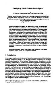
x� the topological relationships between the objects (disjoint, meet, overlap, etc.). For 3D objects relationships we must also consider here if the object is placed in front of, inside or behind the other object [2]; x� the directional relationships between the objects (left, right, above, above-left, etc.); x� the distance/metric relationships between the objects (outside 5 cm, inside 2 cm, etc.). A N-dimensional projection relation is a N-tuple of 1D relations, e.g. 5� = (5�,5 ). Each 1D relation corresponds to the relationship between the N-dimensional objects in one of the dimensions. So if V�is the number of possible 1D relations at a particular resolution, the number of ND � relations that can be defined at the same resolution is V . According to the requirements of the particular application, not all dimensions need to be tuned at the same resolution, in which case the maximum number of ND relations is the product of the corresponding numbers for each dimension. Figure 3 illustrates the 169 (132) primitive projection relations between regions on the plane, on the initially discussed (Allen's) resolution scheme. All previous properties can be analogously extended to N dimensions. 3
R1_j
R13_j
Ri_1
Ri_13
Figure 6. Spatial composition of the Image-guided interaction space.
Figure 3.Relations between 2D regions adapted from [2].
The real scenario of this description is illustrated in Figure 5 and the spatial composition (interaction space layout) of the above scenario is illustrated in Figure 6, while the temporal one will be discussed in the next sub-section. The directional and relational relationships between the objects in many applications of augmented reality result from the registration procedures to mix in the correct way real and digital worlds. For instance, the AR systems which are based on markers recognition in order to relate the real and virtual worlds (such as those using ARToolKit1 library), assume that the marker is in x-y plane, and z axis is pointing downwards from the marker plane. So, vertex positions can be represented in 2D coordinates by ignoring the z axis information and then the virtual object can be placed in a (x, y, z) position related to the center of the marker.
Figure 4.Spatial relationships.
These spatial aspects can be defined by: 1. designer (while design time), 2. by user 3. or by the system (while the application progresses). This classification will be used as a VSDWLDOBFRQWUROB,' parameter in the composition of mixed interaction spaces. The spatial integration of objects into the interaction space is a relevant aspect since that information facilitates processing through efficient allocation of attentional
����� �� � ������ � ������ ����� ����� � �� . 1
More information about ARToolKit can be found at http://www.hitl.washington.edu/research/shared_space/dow nload/
4
the tracking system and they disappear according to user’s interaction.
resources. For instance an adequate spatial integration of the objects can facilitate the user’s interpretation.
�
�
��� ��������� �
Besides the spatial aspects related to the integration of CIO into MIU we should also consider the temporal aspects that involve all participating media objects (e.g. visual and sound). As mentioned in [1] synchronization can be represented by thirteen possible temporal relationships considering the operation inverse for each relationship except for the equal relation. Basically there are two types of temporal synchronization: sequential (EHIRUH� relation) and simultaneous (that can be HTXDO, PHHWV, RYHUODSV, GXULQJ, VWDUWV, or ILQLVKHV relations). Note from table 1 that all simultaneous relationships (such as RYHUODSV, GXULQJ, VWDUWV, and ILQLVKHV � can be generalized as the HTXDO relation by inserting some delay time when it is needed. For example in the [�EHIRUH�\ relation there is a time space better than zero between [ and \ and at the [�PHHWV�\�relation the space-time is zero between [ and \.
Figure 7. Temporal composition of the Image-guided surgery example given in Figure 6.
*+,-./01+ 21+/-3/ 14 5-6 02-, 7+5 0+/-.72/01+ ,872-,
Besides spatial and temporal integration of interaction space objects it is important to understand how the insertion of devices and interaction spaces in the environment can contribute to a better interaction. According to the user’s focus while performing a task we have identified four spatial zones for an insertion device considering the level of periphery (see Figure 8):
Table 1. Seven Allen’s relation and their inverse.
� ��� ���� � �� �� �������� � ������� � ������� !"#"$%&$' &( )'
Relation
ID 1 2 3 4 5 6
� �� �� � � �� ��
ID 8
1.
Central zone: it corresponds to a device insertion distance of 0 to 45cm from the user’s task focus.
9
2.
� ������� � ������ � '!"#"$%&$
10
Personal zone: it corresponds to a device insertion distance of 46cm to 1.2m from the user’s task focus.
3.
Social zone: it corresponds to a device insertion distance of 1.3 to 3.6m from the user’s task focus.
4.
Public zone: it corresponds to a device insertion distance bigger than 3.6m from the user’s task focus.
Relation
11 12 13
7
The four possible insertion context type discussed here will be used as ,QVHUWLRQB&RQWH[WB,' parameter in the composition tuple of mixed interaction spaces.
The interaction space objects synchronization is defined according to the task requirement. Another aspect is that we can have different types of control. For instance a virtual object can be displayed automatically in the interaction space when a determined object is recognized in the real world or it can be done under user’s demand. Then the temporal control integration can be defined by: 1.
User (e.g. during execution time)
2.
System (e.g. during execution time)
3.
Third part (e.g. defined by an agent system which is capable of making decisions and initiating actions during execution time independently)
This classification will be used as a WHPSRUDOBFRQWUROB,' parameter in the composition of mixed interaction spaces.
Figure 8. Zones of insertion context according to user’s task focus. 1.Central zone; 2.Personal zone; 3.Social zone and 4.Public zone.
Figure 7 shows the temporal synchronization diagram related to the spatial diagram illustrated in Figure 6. The text objects C, D and E appear automatically according to
If the device is inserted in the central zone of the user’s task, s/he does not need to change her/his attention focus to perform the task. Otherwise if the user is changing the 5
��� Interaction focus on Virtual World without shared attention (VW): in this case the interaction is focused on only one item in the virtual world. There are no virtual items competing for user’s attention.�
attention focus all time, then in this case it is probable that the device is inserted outside from the central zone and so in a peripheral context of use (Figure 9). In the Museum project, one application of NaviCam system [7], the device is inserted in the central context of the user’s tasks, therefore she doesn’t need to change her attention focus to perform the task. Otherwise if the information is displayed in a screen in the museum room and the user needs to look at the screen and after that look at the painter and so s/he changes her/his attention focus all the time, then in this case the device is inserted in peripheral context.
��� Interaction focus Shared in the Real World (intra-world interaction focus, SRW): in this case the interaction focus is shared between items in the real world. � ��� Interaction focus Shared in the Virtual World (intraworld interaction focus, SVW):� in this case the interaction focus is shared between items in the virtual world. � ��� Interaction focus Shared between Worlds (inter-world interaction focus, SW):� in this case the interaction focus is shared between items belong to different worlds (real and virtual).� The five possible interaction focus types discussed here will be used as ,QWHUDFWLRQB)RFXVB,' parameter in the composition tuple of mixed interaction spaces.�
� ������ �� �*�*
�*��� * ���� �* ��� ��
Figure 9. Example of insertion contexts regarding the user’s task focus. Left picture shows insertion context of interaction spaces in Personal zone and the right picture shows insertion of interaction space in Central zone.
This declarative definition should be transformed into an internal representation that captures the topological, directional, temporal relationships as well user’s interaction focus and insertion context of IS. Here we propose a definition model to support these needs.
,-.�, 0+/-.72/01+ 412�,
When there are multiple sources of information and two worlds of interaction (real and virtual) we must choose what to attend to and when. At times, we need to focus our attention exclusively on a single item without interference from other items. At other times, we may need to timeshare or divide our attention between two (or more) items of interest, which can be part of the same or a different world.
Then the composition of a mixed interaction space consists of several LQGHSHQGHQW fundamental compositions.
The term LQGHSHQGHQW implies that objects participating in these compositions are not related implicitly (either spatially, or temporally, or by interaction focus or insertion context), except for their implicit relationship at the start point .
For example in the Museum project [7] the user wears a see-through head-mounted display in which information about an exhibit is displayed. The user is thus able to perceive real objects (the exhibit) and added synthetic information. The object of the task here is the painting of the exhibit. Therefore, the user’s interaction focus is shared between virtual and real objects.
Thus, all compositions are explicitly related to . We call these compositions FRPSRVLWLRQ� WXSOHV, and these include spatially and/or temporally related objects. MIS composition = {[6SDWLDOB,QWHJUDWLRQ], [7HPSRUDOBLQWHJUDWLRQ], [,QWHUDFWLRQB)RFXV], [,QVHUWLRQB&RQWH[W]}
Following the definition given by [3] the user is performing a task in order to manipulate or modify an object of the real world, and then the task focus is on the real world; or an object of the virtual world whose task focus is on the virtual world.
Where: 6SDWLDOB,QWHJUDWLRQ parameters:
contains
the
following
optional
>6SDWLDOB,QWHJUDWLRQ@� ��UHODWLRQBW\SHB,'��9���9���[��\�� VSDWLDOBFRQWUROB,' �
Therefore, by considering all possibilities of interaction focus while the user is performing a specific task, we have found five possible combinations:
5HODWLRQB7\SHB,' is given by one of the possible relationships presented in [2], which also explores the possibility to extend them to 3D relationships.
��� Interaction focus on Real World without shared attention (RW): in this case the interaction is focused on only one item in the real world. There are no real items competing for user’s attention.�
6SDWLDOBFRQWUROB,' represents who has the spatial control: designer, user or system, respectively.
6
9�� DQG� 9�� are the closest vertices between two objects $� and %, respectively, and [��\ are the horizontal and vertical distances between YL��YM.
F�� ���
� >�5�B��� B�� 9�B&�� B�� ���� ���� GHVLJQBFRQWURO �� �GXULQJ�� XVHUBFRQWURO ���6: @�
The 7HPSRUDOB,QWHJUDWLRQ can have the following optional parameters:
&� >�5��B���� 9�B&�� 9�B'�� ��� ���� GHVLJQBFRQWURO �� �HTXDO�� XVHUBFRQWURO ���69: @�
>7HPSRUDOB,QWHJUDWLRQ@� ��UHODWLRQBW\SHB,'�� WHPSRUDOBFRQWUROB,' �
'�>�5��B���� 9�B'��9�B(������ ����GHVLJQBFRQWURO ���HTXDO�� XVHUBFRQWURO ���69: @�
5HODWLRQBW\SHB,'� is given by one of the Allen’s relations ID represented in Table 1.
(��
,W� LV� LPSRUWDQW� WR� VWUHVV� WKDW� in composition tuple c3 represents the spatio-temporal origin of the Menu_options. In this example, we have a composition of MIS (mixed interaction space). It has to be stressed that, when the host MIS (i.e., IGS_interactionSpace) ends, all the MIS started by it are also stopped (i.e., Menu_options). There is an issue regarding the mapping of the spatio-temporal specifications into the composition tuples: the classification of involved objects. The proposed procedure is the following: For each object $L, we check whether it is related to objects already classified in an existing tuple. If the answer is positive, Ai is classified in the appropriate composition tuple (a procedure that possibly leads to reorganization of the tuples). and Otherwise, a new composition tuple, composed by $L, is created.
7HPSRUDOBFRQWUROB,' represents who has the temporal control: user, systems or third part, respectively. The ,QWHUDFWLRQB)RFXV and ,QVHUWLRQB&RQWH[W don’t have sub-parameters, then: ,QWHUDFWLRQB)RFXV corresponds to the user’s interaction focus parameter during an interaction. This parameter is defined for each composition and it can assume one of the 5 possible values discussed in the previous subsection; ,QVHUWLRQB&RQWH[W corresponds to the insertion context of the interaction space into the environment. This is a parameter defined only for the main interaction space composition. It can assume one of the 4 possible values discussed in the previous subsection.
�/21
The objects to be included in a composition tuple of a MIS are those that are spatially and/or temporally and/or focus shared related. In our example (Figure 6 with spatial integration description and Figure 7 with related temporal integration description) A and B and C should be in the same composition tuple, since A relates to B and B relates to Menu_options. On the other hand, if an object is not related to any other object, neither spatially nor temporally, so it composes a different tuple. The above specifications defined in a high-level are transformed into the following model language considering our example of IGS_InteractionSpace composition:
-,
During the application development process, it is probable (especially in the case of complex and large applications) that authors would need information related to these relationships. The related queries depending on the spatial, temporal, interaction focus and insertion context relationships maybe be classified in the following queries categories:
FRPSRVLWLRQ� �^F���F�`�
x� pure spatial or temporal query: only a temporal or a spatial relationship is involved in the query. For instance, “which objects always overlap the presentation of live video A?”, “which objects spatially lie above object B in the interaction space?”.
� >�5�B��� B�� 9�B$�� ��� ��� GHVLJQHUBFRQWURO �� �HTXDO�� XVHUBFRQWURO ���5: ���=RQH� @�
x� spatio-temporal query: where such a relationship is involved. For instance, “which objects spatially overlap with object A during its presentation?”.
F�� ��
$��
x� MIS query: spatial or temporal layouts of the application considering interaction focus and insertion context. For instance, “what is the spatial integration (layout of MIS) when the user’s interaction focus is shared between A and B?”, “which objects are presented when the user’s focus interaction is focused on the real world?”, “when the user’s focus is on the real world how is the insertion context of MIS?”, “when the user has the temporal control of presentation where is located the user’s interaction focus?”
,*6B,QWHUDFWLRQ6SDFH� F�� �
� >�5�B��� B�� 9�B%�� B�� B�� V\VBFRQWURO �� �GXULQJ�� V\VBFRQWURO ���6: @� %� >�5��B���� 9�B%�� 9�B0HQX�� ���� ���� GHVLJQBFRQWURO �� �GXULQJ��XVHUBFRQWURO ���6: @� 0HQXBRSWLRQV�
The answers of such queries may indicate the potential problems during interaction such as discontinuous interaction. For instance if the user has the temporal control
��0HQXBRSWLRQV�
FRPSRVLWLRQ� �^F�`� 7
W., E. (eds.), in Conference Proceedings of DARE2000, ACM, Ellsinore - Denmark, April 2000, p.165-167.
during an interaction and his interaction focus is under some object in the real world, so he/she probably will change between operation modes and attention focus to control, or to interact with the presentation. It characterizes a functional and perceptive discontinuity during interaction conforming discussed in [10]. Queries like that can be automatically acquired during design time.
4. Milgran, P., Herman, C. J., A Taxonomy of Real and Virtual World Display Integration, in 0L[HG� 5HDOLW\�� 0HUJLQJ� 5HDO� DQG� 9LUWXDO� (QYLURQPHQWV, Ohmshda & Springer-Verlag, pp 5-30, 1999. 5. Nigay, L., Dubois, E., Renevier, P., Pasqualetti, L., Troccaz, J., Mixed Systems: Combining Physical and Digital Worlds, &RQIHUHQFH� SURFHHGLQJV� RI� +&,� ,QWHUQDWLRQDO, Crete - Greece, 2003, pp.1203-1207.
�� ������ In this work we have reviewed and extended some approaches to design mixed interaction spaces. With that we have predictively modeled user interaction to evaluate design strategies and support adaptation for continuous interaction while dealing with mixed spaces of interaction.
6. Poupyrev, I., etc all. Developing a generic augmented reality interface, ,(((�&RPSXWHU, vol. 35, n.3, 2002. 7. Rekimoto, J and Nagao, K., The World through the Computer: Computer Augmented Interaction with Real World Environments, 8VHU� ,QWHUIDFH� 6RIWZDUH� DQG� 7HFKQRORJ\� 1995.
As contributions of this work we have highlighted: x� Manage large number of options for the MIS design under development of MR systems.
8. Rekimoto, J. and Saitoh, M., Augmented Surfaces: A spatially Continuous Work Space for Hybrid Computing Environments. &+,¶��, 15-20, May, 1999.
x� Acquire spatial, temporal and focused layouts of the MIS under development of MR system for verification purposes such as those related to continuous interaction.
9. Trevisan, D., Vanderdonckt, J., Macq, B., Raftopoulos, C., ³Modeling Interaction for Image-Guided Procedures”, Proceedings of International Conference on Medical Imaging SPIE2003 (San Diego, 15-20 February 2003), K. Hanson, C.-T. Chen, E.L. Siegel (eds.), International Society for Optical Engineering, 2003, pp.108-118.
x� Help designers to envision future interactive mixed systems. Finally we should be aware that specific design aspects such as spatial and temporal integration of different media objects have implications for the human perception. However the information that people assimilate from a modality of interaction (e.g., visual modality) also depends on their internal motivation, what they want to find and how well they know the domain.
10.Trevisan, D., Vanderdonckt, J. Macq, B., “Continuity as Usability Property”, Proc. of 10th International Conference on Human-Computer Interaction HCI International’2003 (Heraklion, 22-27 June 2003), C. Stephanidis (ed.), Lawrence Erlbaum Associates, Mahwah, 2003.
� ��� � � ��� We gratefully acknowledge the support from the Région Wallonne under contract WALEO 21/5129. The work described here is a part of the MERCATOR project available on http://www.tele.ucl.ac.be/PROJ/MERCATOR_MULTI_e.h tml
11.Vanderdonckt, J. and Bodart, F., Encapsulating Knowledge for Intelligent Interaction Objects Selection, 3URFHHGLQJV� RI� ,QWHU&+,¶��, ACM Press, New York, 1993, pp. 424-429.
� � � � �
1. Allen, James F., Maintaining knowledge about temporal intervals. Communications of the ACM Volume 26 , Issue 11, pp 832 – 843, November 1983.
12.Vazirgiannis, M., Theodoridis, Y., and Sellis, T.. Spatiotemporal composition and indexing for large multimedia applications. 0XOWLPHGLD� 6\VWHPV n.6, 1998. SpringerVerlag, pp. 284–298.
2. Delis, V., Papadias, D., Querying Multimedia Documents � By Spatiotemporal Structure. Proceedings of the �� ,QWHUQDWLRQDO� &RQIHUHQFH� RQ� )OH[LEOH� 4XHU\� $QVZHULQJ� 6\VWHPV, Denmark, Springer-Verlag LNCS, 1998.
13.Watts, Leon (2000), “The Magic Board, an Augmented Reality Interactive Device Based on Computer Vision”. Workshop on Continuity in Human Computer Interaction, April 2 and 3, 2000, Scheveningen, Netherlands.
3. Dubois, E., Nigay, L., (2000), "Augmented Reality: Which Augmentation for Which Reality?", in Mackay,
�
8