most promising application fields; cf. ... data intensive building model information on thin mobile clients. ... smoothly and the user interaction of the application.
Software Architecture for Mobile Mixed Reality and 4D BIM Interaction M. Hakkarainen, C. Woodward, K. Rainio VTT Technical Research Centre of Finland, Espoo, Finland
ABSTRACT: This article describes a software architecture for providing mobile user at the construction site with two-way real-time augmented reality access to 4D CAD and BIM information. The system covers all the components from content creation and positioning tools, through wireless data sharing and mobile interaction, up to augmented visualisation and feedback from the site. Special emphasis is placed on managing different model formats, linking them to 4D information, placing the models in geo coordinates, as well as managing data intensive building model information on thin mobile clients. We also discuss various interaction aspects, vision based and sensor based tracking methods, as well as tools for high-end architectural AR visualisation. 1 INTRODUCTION Augmented Reality (AR) [Azuma 1997], [Azuma et al. 2000] is a visualisation technology for displaying virtual models real time in real world locations, with building and construction as one of the most promising application fields; cf. [Klinker et al. 2001], [Woodward et al. 2007]. Recent developments in mobile processing units, camera quality, different sensors, wireless infrastructure and tracking technology enable AR applications to be implemented even in demanding mobile environments, see e.g. [Pasman and Woodward 2003], [Izkara et al. 2007], [Behzadan 2008]. Building Information Models (BIM) are another main technology driver increasingly used for data sharing and communication purposes in real estate and construction sector, cf. [Koo and Fisher 2000], [Kähkönen and Leinonen 2003]. Combined with Augmented Reality, 4D BIM models could facilitate comparisons of the actual situation at the construction site with the building’s planned appearance at the given moment. Such mobile augmented information available at the construction site would have various applications for construction work planning, verification, training and safety, as well as for communication and marketing prior to construction work. The related AR tracking technologies open up further application scenarios. Knowing where the user points the camera makes it possible to implement mobile location based visual feedback from the construction site to the CAD and BIM systems. We may think of adding elements of reality e.g. images, reports and other comments to the virtual
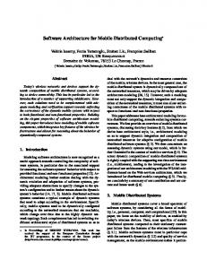
4D model, with full awareness of the user’s location in time and space. Altogether, the tracking and interaction techniques can thus be made to serve the complete spectrum of Mixed Reality [Milgram and Kishino 1994], forming a seamless interaction cycle between the real world (augmented with virtual 3D/4D model data) and digital building information (augmented with real world data); see Figure 1.
Figure 1. Mixed reality interaction cycle: mobile view of construction site augmented with BIM information (arrow down), and visual feedback from mobile device back to BIM system (arrow up).
The AR4BC project (Augmented Reality for Building and Construction) between VTT and industrial partners from the Finnish B&C sector aims to providing the mobile user at the construction site with direct two-way access to 3D CAD and 4D BIM information. The expected benefits for application users are photorealistic augmented visualisations of architectural plans, mobile access and feedback to digital building data during and after construction, improved communication, and increasingly versatile use of BIM models. This article describes the overall AR4BC software architecture, from content creation (4DStudio) and positioning tools (MapStudio) through onsite visualisation (OnSitePlayer) and wireless data sharing (OnSiteServer) up to mobile interaction and visualisation (OnSiteClient). Special emphasis is on authoring tools, i.e. managing different model formats, linking them to 4D information, placing the models in geo coordinates, as well as managing complex data intensive building model information on thin mobile clients. We also discuss model based tracking and other methods to match the camera view with the virtual model description of the building and its environment, visualisation and interaction tools, as well as the feedback mechanisms to be enabled; however these are still ongoing work and less detail will be given thereof. The remainder of the article is organized in a further four sections. In Section 2, we take a brief look at our previous work conducted in this area. In Section 3, an overview is provided of the current system architecture, extended in Section 4 into a more detailed description of the system’s implementation and its usage. Conclusions and items for future work are presented in Section 5. 2 PREVIOUS WORK In our previous work [Honkamaa et al. 2007], we developed a software for outdoor augmented reality visualisation, using the building’s geo coordinates in combination with the user’s GPS coordinates and markerless motion flow based tracking. The virtual model was mapped on the geo coordinate system using Google SketchUp and/or Google Earth [GE 2009], [GE SketchUp 2009]. The 3D model data with location information was then saved on Google Earth KML/KMZ file format [KML 2009]. This approach required using the Collada file format [Collada 2009] for models in our visualisation software. The Collada model format presented one of the first problems with the system. Only few construction engineering or architect design softwares were able to export their models into Collada. In these cases, the 3D Studio Max 3DS format [3DSMax
2009] was the only feasible option to import the model into the Google Earth, by using first the Google SketchUp. However, Google SketchUp was in some cases unable to handle large models smoothly and the user interaction of the application was sometimes extremely slow. Exporting the model from the SketchUp to Google Earth required (automatic) model conversion which could take up to tens of minutes with larger models. The ArchiCAD system has a free plug-in available for placing the models in Google Earth. However, this approach did not always work with the OpenSceneGraph’s Collada plug-in. Also the ArchiCAD’s exported Collada models do not always pass the Collada.org’s coherency tests. Rendering in our applications is based on the OpenSceneGraph (OSG) [OSG 2009]. OSG’s Collada plug-in also supports exporting the model (conversion from one format to Collada), but in some cases Google Earth was not able to visualize these models. This happens especially when the model has Collada triangle strip primitives, which Google Earth’s Collada implementation does not support. Our previous system was originally designed to handle just one model at the time. This limitation was a major obstacle for creating visually rich scenes on the construction site. Furthermore, the system did not facilitate masking of the virtual model with (models of) existing buildings so the realism of the visualisation suffered significantly in some cases. In the AR4BC project we have identified various new requirements for construction site authoring and visualisation. The model should incorporate also the 4th dimension (time). We wish to implement a feedback system from the construction site to the studio software. The application requires sophisticated tracking and positioning systems like electronic compass and inertia sensors and visual based methods for model and feature based tracking. With all the new requirements, and facing all the problems and limitations of the existing system, we decided to re-design and implement the visualisation software and the authoring tools to meet the project and domain needs better. 3 SYSTEM OVERVIEW 3.1 Hardware Our office-based authoring applications (4DStudio and MapStudio) can be used on basic off-the-shelf PCs with reasonable 3D display hardware, keeping in mind the requirements of the CAD systems. The onsite visualisation systems (OnSitePlayer and OnSiteClient extension) is developed with a lightweight UMPC (Ultra Mobile PC) such as the
Sony Vaio UX in mind. However, stand-alone operation of the full functionality (OnSitePlayer) with complex BIM models typically requires a high-end laptop including good 3D display hardware. The GPS positioning information is received from the external GPS module via Bluetooth connection. Basically any GPS module with Bluetooth connection supporting virtual serial port communication can be used. For sensor based tracking we are currently using OS5000-US Kit 3 axis Digital Compass from OceanServer Technology Inc. [OST 2009]. This sensor provides azimuth values with pitch and roll information. Compass is used for model positioning with GPS values and in tracking mode we utilize 3-axis information for tracking the camera movement.
can be used to mask the main construction model, or to add visual information of the surroundings. OnSitePlayer is the main augmented reality visualisation, interaction and feedback software for the construction project on the construction site. OnSitePlayer is able to visualize the models in right position (location, orientation and perspective) by utilizing the model’s GPS coordinates in combination with the user’s position. User positioning can be done automatically using GPS, or manually defined on the site.
3.2 Software modules The prototype system is divided in three parts; 4DStudio, MapStudio and OnSitePlayer (see Figure 2). The Studio applications are in an authoring role of the system while the Player provides a rich augmented reality view and mobile feedback interface at the construction site. OnSitePlayer can be operated either as a stand-alone, if there is enough processing power and memory on the mobile device, or as a client-server solution distributing the heavy computation to the server, and interaction and display to the client. For rendering we use OpenSceneGraph 2.8.0 [OSG 2009] and the GUI is built using the wxWidgets 2.8.9 [wxWidgets 2009]. The applications can handle all OSG supported file formats via OSG’s plug-in interface (e.g., OSG’s internal format, 3DS, VRML) as well as IFC, using the parser module developed by VTT. The 4DStudio software is responsible for handling and modifying the 4th dimension i.e. the timing information of the BIM model. It allows the user to define the construction timing related values part by part. The visualisation of the workflow in certain time range is also a central feature. The 4DStudio software also provides a user interface to browse and visualize incoming reports from the construction site, created by the user with the OnSitePlayer. The MapStudio software is used to map the BIM models in geo coordinates (GPS+orientation). Now we don’t insert the building model into Google Earth like in [Honkamaa et al 2007], instead we capture the Google Earth geo information into our application. Other map data bases could be used as well. The MapStudio can also be used to add some additional models around the construction site, so called block models. The block models
Figure 2 System overview
Virtual models of the construction sites can be very complex and consequently mobile devices used for onsite visualisation may not be capable of smooth real time augmentation. To overcome this problem we employ the client-server architecture. The OnSiteClient software is used on the construction site for tracking and for visualizing a 2D image of the model, i.e. the 3D model projected to the client’s viewing coordinates. The viewing projection is provided by the server software OnSiteServer and it needs to be updated only once in a while (not real time). Both the OnSiteClient and OnSiteServer modules are obtained as extensions of the stand-alone OnSitePlayer software with relatively small modifications. The tracking algorithms are implemented in our augmented reality subroutine library ALVAR (A Library for Virtual and Augmented Reality). It
provides generic solutions for marker and markerless vision based tracking, as well as for hybrid solutions using electronic sensors. ALVAR will be available for public distribution at our home pages [VTT 2009] in the near future. 4 IMPLEMENTATION 4.1 4D BIM definition and interaction In the general case, the input geometry for the application should be provided as 4D BIM model(s). In some cases the model with time information might be available, but if not, 4DStudio can be used to link it. As inputs the 4Dstudio program takes the building model (in IFC or some other format) and the construction project schedule (in MS Project XML format). Typically, the part names and the generated part identifiers (GUIDs) of the construction project are not the same as in the building IFC model. Thus, automatic mapping is usually impossible, so the user must manually link the construction project parts to the IFC building model parts using 4DStudio. To facilitate the linking, the program allows the use of project hierarchies, so a large number of building parts can be linked at once. After the linking is done, the user can use a slider to move to various time points within the construction project schedule. The program uses part color coding to show which building parts are finished, under construction, or not yet started at that time. As an output, 4DStudio provides project description files including the model itself and the timing information as an XML file. The user can select which colours (incl. transparency) are used to visualize finished vs. under construction vs. not yet started parts. Besides, colour shades can optionally be used to distinguish various part types (e.g. doors vs. walls) from each other. Also clip planes are available. See Figure 3. Finally, the feedback reports from the construction site can be presented within the 4DStudio software. The feedback reports are used to document various notes, verifications and problems detected on site. Typically, they contain text descriptions of the issue, perhaps photographs, time stamps, and position information. All these pieces of information are assembled into a single XML file, which is kept separate from the original model files, but can be viewed together with the model using 4Dstudio.
Figure 3. 4DStudio presenting a partially constructed building, parts currently under construction shown in green. The slider displays the whole project duration and the current time within it.
4.2 Model placement in geo coordinates The MapStudio application is used to place the model in the GPS coordinates at the construction site. In our current prototype system, we use Google Earth as the map and GPS information provider via Google Earth COM API. MapStudio initializes the Google Earth application by the user’s request. It is the user’s responsible now to locate the construction site in the Google Earth’s view, and to select the viewing range to allow adding the main model and additional block modules. When the required view is defined, the user switches back to MapStudio and asks the software to capture the current map view. MapStudio captures the current Google Earth’s view and gathers the view’s GPS values via Google Earth COM API. Now the map layout is available in MapStudio and the GPS information is mapped on the rendering coordinates and vice versa (Figure 4).
Figure 4. MapStudio with a map captured from Google Earth.
After defining the map, the user can start adding building model(s) on the map layout. The models can be any OpenSceneGraph supported format or IFC format. The user can control the model positioning and orientation numerically, or by mouse by using simple OSG draggers (Figure 5). The user can also define the GPS coordinates numerically.
Figure 5. Model placed on the map, using rotation dragger.
4.3 Mobile interaction OnSitePlayer is able to utilize a GPS unit via Bluetooth communication channel and USB port attached 3-axis digital compass. The user interface is implemented with a light weight, small display, stylus operated mobile device in mind. Therefore the interaction should require as little keyboard access as possible. The application provides two separate views in tabs; map layout of the site with the models including the user location and viewing direction (Figure 6), and the augmented view with the real time video feed (Figure 7).
The map layout of the Player shows the current user position on the area. This location can be updated in real time using the attached GPS module or by hand (virtual GPS). The virtual GPS approach allows the system utilisation on the site also indoors, under roofs or other obstacles, or even without GPS hardware. The model can be clipped on the view by using clipping planes (6 clipping planes, 2 for each axis). The model can also be shown partially transparent to see the real structures behind virtual ones. This allows detailed examination of the current part of the model on site. The user is also able to take a video or a snap shot of the augmented view and save it to a file. This allows for further examination of the construction site at the office. The construction site ensemble might include several block models that are used for masking the target building. Usually these block models are not visible, but in some cases the user might found these models helpful to model positioning. For these purposes, the user is able to modify some of the block model’s visualisation properties show/hide, etc. In case the user is operating with a 4D model, he/she is also able to control the construction site visualisation based on the work flow timing information. There are several options for time based visualisation; e.g. parts currently under construction, parts constructed and parts to be constructed on selected time scale. User created mobile reports from the construction site include still image of the target position (optionally not augmented) and textual information added by user. The report is assigned to the construction site by time information and by model coordinates. These reports may be uploaded for review in 4DStudio either from the construction site using wireless connection, or separately after the user returns to the office. 4.4 Tracking
Figure 6. OnSitePlayer’s map view. User position and looking direction is visualized by red camera icon.
Based on the user location (by GPS) and building positioning on the map, OnSitePlayer calculates the model orientation and position related to the user, and visualize the model(s) in correct size and perspective. For augmenting, we need further the viewing direction which is normally obtained from electronic compass. In case there is no GPS and/or compass available, the user can define the approximate view direction interactively, by selecting the so-called pointing model from the map layout. The performance of digital compass is typically not sufficient for placing the model as accurately as required. Instead, our goal is to use model based optical tracking for accurate positioning of the model to the camera view. Model based tracking
requires known features of the virtual model to be detected from the video view, cf. [Lepetit et al. 2003], [Reitmayr and Drummond 2006]. In our case, the 4D BIM model provides us with an ideal of what elements the camera view should contain at each point of time. As long as model based tracking is able to keep the model on the view, the user can freely move around and pan the view, and the model is kept locked in the right position. Instead of model based tracking, however, this part is often better to perform with feature based tracking [Davison et al. 2003], or motion flow based tracking [Honkamaa et al. 2007]. These are much easier to implement in real time than model based tracking, especially in case of complex models model based tracking needs then to be called only occasionally to avoid drift. The 3-axis compass accuracy is disturbed by the end user devices (i.e. computer, camera and GPS module) and this will require more study. The compass could be installed farther away from the other devices but then the system is not so compact anymore. Another option is to use some shielding for the compass sensor. On the other hand, vision based tracking systems can be severly affected by moving objects, e.g. people or cars in the video feed. Ultimately, combining vision based tracking and sensors into a hybrid solution (sensor fusion) would provide further reliability to tracking and model positioning on the video image.
complete 3D/4D models and process all the information in real time. However, if the construction site model is too complex for the mobile device to be rendered in reasonable frame rate, the client-server solution can be employed. For this scenario, OnSitePlayer has server and client extensions which have been obtained with small modifications to the Player code. The client extension OnSiteClient is used on the mobile device at the construction site. The client is responsible to gather position and orientation information, but instead rendering the full 3D model, the client just passes the user location and view direction to the server. The server uses this information to calculate the correct model view. The view is represented as a 2D still image of the model projected in the viewing plane, together with a bitmap telling which parts of the image are transparent (not containing the model). After receiving the image and bitmap back, the client is able to superimpose the 2D projected image on the screen, correctly masked at the right position. For further details see our previous work [Pasman and Woodward 2003]. As long as the user position in geo coordinates does not change much (i.e. the user does not walk while viewing), and the camera movements are relatively small (e.g. under 15 degrees), we can use the same image locally on the mobile device for panning around. A new still image from the server is required only when the user position or viewing direction changes significantly. More sophisticated and accurate augmenting methods will be studied in our future work as well. 4.6 Rendering
Figure 7: Visualizing the model on site.
4.5 Client-server extensions The OnSitePlayer has three operation modes: stand-alone, client and server. In the normal case the Player is used in the stand-alone mode on the construction site. The Player should then be able to load the project description file together with the
Photorealism is an important aspect of the application, especially when visualizing architectural CAD models of the building. The system can simulate real world lighting by creating virtual sunlight based on the current time and GPS information. Lighting can further be controlled with manually operated sliders, or semi-automatically by selecting predefined weather conditions (sun, cloudy, rain). The lighting controls also allow adding soft shadows to the image. Another aspect to account for photorealism is the discrepancy between real time video quality vs. synthetic appearance of the virtual objects. The video feed from the camera suffers from colour degradation, it is usually slightly blurred or out of focus, while virtual models appear unnaturally crisp and sharp. Our plans are to merge the model to the view and to create more realistic augmentation by adjusting the model rendering quality to the video feed quality, cf. [Klein and Murray 2008].
5 CONCLUSIONS AND FUTURE WORK In this article, we have presented a software architecture for mobile augmented reality visualization and interaction with 4D BIM models. The system allows the user to compare scheduled building information models with the situation at the construction site in real time, as well as to attach 3D/4D aligned visual and other feedback to the BIM model. The mobile system can be used either as stand-alone application, or client-server solution. The tracking part of the system is based on hybrid solutions combining map database, GPS, electronic compass, model based and feature based tracking, and user interaction as required. At this point the system is on prototype level and we have focused mainly on authoring and interaction aspects. The current system already exceeds by far the functionality of our earlier implementation: being able to deal with scheduled 4D BIM models; support of general OSG compatible file formats as well as IFC; new interactive tools for object placement in geo coordinates; integration of compass for orientation tracking; completely redesigned user interface with selectable 2D and 3D views; etc. After the minimum requirements of authoring and interaction have been finalized, we will focus more on construction site specific issues and photorealistic visualisation aspects. We will provide a reporting system from the Player to the Studio side, and more informative visualisation techniques for the timing workflow. To create more realistic visualisation of architect models, the system will require sophisticated lighting models based on the current conditions onsite, as well as algorithms to handle the image quality discrepancy between video and virtual models. We are also carrying out research on optical and model based tracking algorithms, to be incorporated in the system. In tandem with vision based tracking research, we survey sensor fusion approaches to combine vision and sensor based tracking into hybrid solutions. The vision based as well as hybrid tracking methods will be implemented as parts of VTT’s ALVAR subroutine library which will be made available for general licensing in the near future. 6 ACKNOWLEDGEMENTS This work has been conducted as part of the ongoing project AR4BC (2008-2010), with VTT as the main developer, companies Skanska, Tekla, Pöyry, Buildercom, Adactive, Deskartes and Sensetrix as industrial partners, and main funding provided by Tekes (Finnish Funding Agency for Technology and Innovation).
The building and BIM images in Figure 1 are provided by Tekla. The 4D example model in Figure is of the Koutalaki hotel, constructed by YIT. The examples in Figures 4-7 are related to a pilot project we are carrying out with a Skanska commercial development project in Helsinki. 7 REFERENCES 3DSMax 2009. Autodesk 3ds Max, http://usa.autodesk.com/adsk/servlet/index?siteID=123112&id=5659302 ArchiCad 2009. ArchiCad Google Earth Connection, http://www.graphisoft.com/products/archicadsolutions/google_earth_connection.html Azuma R. 1997. A survey of augmented reality, Presence: Teleoperators and Virtual Environments 6, 4 (Aug 1997), pp. 355 - 385. Azuma R., Baillot Y., Behringer R., Feiner S., Julier S., MacIntyre B. 2001. Recent advances in augmented reality, IEEE Computer Graphics and Applications 21, 6 (Nov/Dec 2001), pp. 34-47. Behzadan A.H. 2008. ARVISCOPE: Georeferenced Visualisation of Dynamic Construction Processes in ThreeDimensional Outdoor Augmented Reality, PhD Thesis, The University of Michigan, 2008. Collada 2009. Collada.org, http://www.collada.org/ Davison A.J., Cid Y.G., Kita N. 2004. RealTime 3D SLAM with WideAngleVision, in Intelligent Autonomous Vehicles, 2004. GE 2009. Google Earth http://earth.google.com/ GE API 2009. Google Earth COM API, http://earth.google.com/comapi/ GE Sketchup 2009. Google SketchUP, http://sketchup.google.com/ Honkamaa P., Siltanen S., Jäppinen J., Woodward C., Korkalo O. 2007. Interactive outdoor mobile augmentation using markerless tracking and GPS, Proc. Virtual Reality International Conference (VRIC), Laval, France, April 2007, pp. 285-288. Izkara J.L., Perez J., Basogain X., Borro D. 2007. Mobile augmented reality, an advanced tool for the construction sector, Proc. 24th CIB W78 Conference, Maribor, Slovakia, June 2007, pp. 453-460. Klein G., Murray D. 2008. Compositing for Small Cameras, Proc. The 7th IEEE International Symposium on Mixed and Augmented Reality (ISMAR 2008), Cambridge, UK, September 2008, pp. 57-60. Klinker G., Stricker D., Reiners D. 2001. Augmented reality for exterior construction applications, in Augmented Reality and Wearable Computers, Barfield W. and Claudell T. (eds.), Lawrence Elrbaum Press 2001. KML 2009. KML Documentation Introduction, http://code.google.com/apis/kml/documentation/ Koo, B., and Fischer, M. 2000. Feasibility study of 4D CAD in commercial construction, Journal of Construction Engineering and Management, Vol. 126, No. 4, July/August 2000, pp. 251-260. Kähkönen, K., and Leinonen, J. 2003. Visual product chronology as a solution for accessing building product model data, in CIB W78 2003 conference in Auckland, New Zealand. Lepetit V., Vacchetti L., Thalman D., Fua P. 2003. Fully automated and stable registration for augmented reality applications, Proc. The Second IEEE and ACM International Symposium on Mixed and Augmented Reality (ISMAR 2003), Tokyo, Japan, October 2003, pp. 93-102.
Milgram, P. and Kishino, F. 1994. A Taxonomy of Mixed Reality Visual Displays, IEICE Transactions on Information Systems, Vol E77-D, No 12, December 1994. OSG 2009. OpenScneGraph, http://www.openscenegraph.org/ OST 2009. OceanServer Technology Inc., http://www.oceanserver.com/ Pasman W. and Woodward C. 2003. Implementation of an augmented reality system on a PDA, Proc. The Second IEEE and ACM International Symposium on Mixed and Augmented Reality (ISMAR 2003), Tokyo, Japan, October 2003, pp. 276-277. Reitmayr G. and Drummond T. 2006, Going out: Robust, model based tracking for outdoor augmented reality, Proc. The Fifth IEEE and ACM International Symposium on Mixed and Augmented Reality (ISMAR 2006),Santa Barbara, USA, 22-25 October 2003, pp. 109-118. VTT 2009. VTT Augmented Reality Team, http://www.vtt.fi/multimedia/ Woodward C., Lahti J., Rönkkö J., Honkamaa P., Hakkarainen M., Jäppinen J., Raino K., Siltanen S., Hyväkkä J. 2007. Case Digitalo – A Range of Virtual and Augmented Reality Solutions in Construction Application, Proc. 24th CIB W78 Conference, Maribor, Slovakia, June 2007, pp. 529-540. wxWidgets 2009. wxWidgets, http://www.wxwidgets.org/