that of a relational database, the design of a quality XML document for an ... sideration of dominant applications - the structure of XML document should be.
Designing Quality XML Schemas from E-R Diagrams Chengfei Liu and Jianxin Li Faculty of Information and Communication Technologies Swinburne University of Technology Melbourne, VIC 3122, Australia {cliu, jili}@ict.swin.edu.au
Abstract. XML has emerged as the standard for representing, exchanging and integrating data on the Web. To guarantee the quality of XML documents, the design of quality XML Schemas becomes essentially important. In this paper, we look into this problem by designing quality XML Schemas from given E-R diagrams. We first discuss several criteria in designing a good XML Schema. Following these criteria, transformation rules are then devised that take all constructs of an E-R diagram into account. Finally, a recursive algorithm is developed to transform an E-R diagram to a corresponding quality XML Schema.
1 Introduction XML has emerged as the standard for representing, exchanging and integrating data on the Web. Given that the structure of XML documents is much more flexible than that of a relational database, the design of a quality XML document for an application is non-trivial. By a quality XML document, we mean that it reflects the semantics of the application accurately and can be accessed, updated and integrated efficiently. To guarantee the quality of XML documents, the design of quality XML schemas becomes essentially important. We reckon that several criteria need to be followed in designing a quality schema. (1) information preservation - it is fundamental that the target XML Schema preserves structural and semantic information of the application entirely. (2) highly nested structure - nesting is important in XML documents because it allows navigation of the paths in the document tree structures to be processed efficiently. (3) no redundancy - there is no data redundancy in the XML documents that conform to the target XML schema, thus no inconsistency will be introduced while updating the XML documents. (4) consideration of dominant applications - the structure of XML document should be accommodated such that dominant applications can be guaranteed to be processed efficiently. (5) reversibility of design - the original design can be achieved from the target XML schema, which is fundamentally important to data integration. Kleiner and Lipect [1] proposed a method for generating XML DTD [2] from E-R diagrams. The method preserved as much structural information from E-R diagrams as possible. However, due to the limitation of the DTD, only annotations were used to represent some E-R constructs that have no counterparts in DTD. Many-to-many relationships were translated into top-level elements only so nesting is not maximised. Some advanced features in E-R model such as ISA and aggregation were not considered in their work. Bird et al. [3] proposed an approach to design XML Schemas from the J.X. Yu, M. Kitsuregawa, and H.V. Leong (Eds.): WAIM 2006, LNCS 4016, pp. 508 – 519, 2006. © Springer-Verlag Berlin Heidelberg 2006
Designing Quality XML Schemas from E-R Diagrams
509
Object Role Model (ORM) [4]. The approach considered the dominant applications by analysing the weighting and anchoring of factor types. However, nesting was not discussed in their work. Effort has been put for translating relational database schemas to XML Schemas. An early work in transforming relational schema to XML schema is DB2XML [5]. DB2XML uses a simple algorithm to map flat relational model to flat XML model in almost one-to-one manner. DTD is used for the target XML schema. Based on a flat translation similar to DB2XML, Lee et al. [6] presented two algorithms NeT and CoT. NeT derives nested structures from flat relations by repeatedly applying the nest operator on tuples of each relation. The resulting nested structures may be useless because the derivation is not at the type level. CoT considers inclusion dependencies as constraints to generate a more intuitive XML Schema. XViews [7] constructs a graph based on primary key/foreign key relationship and generates candidate views by choosing the node with either maximum in-degree or zero in-degree as the root element. The candidate XML views generated maybe highly nested. DTD is also chosen for target XML schema. This approach does not consider the preservation of integrity constraints. It also suffers considerable level of data redundancy. Liu et al. [8] proposed an approach that ensures the transformed schema in XML Schema [9] is highly nested, redundancy free and preserves all the integrity constraints. However, the dominant applications and the reversibility of transformation were not discussed in their work. Bohannon et al. [10] developed the notion of DTD schema embedding that preserves information by ensuring both effective invertible mapping and efficient XML query translation. Lots of work has been done on mapping from XML to relational databases for storage purpose. Recently, Barbosa et al. [11] proposed a framework for information-preserving XML-to-relational mapping. The framework is extensible and guarantees the target relational schema is equivalent to the original XML Schema. We aim at designing quality XML Schemas that follows all five criteria we discussed above. Similar to conventional database design, we use E-R model [12] for conceptual modelling, so we assume that E-R diagrams are given when we design XML schema. In this paper, we present our transformation rules and algorithms that automatically generate quality XML Schemas from E-R diagrams by following all five criteria. To preserve information, we choose XML Schema as the target schema language instead of DTD because XML Schema provides far more powerful modelling features than DTD. The rest of the paper is organised as follows. In Section 2, we briefly introduce the E-R model and XML Schema. Following our design criteria, we design transformation rules that consider all the constructs in the E-R model in Section 3. In Section 4, we propose a recursive algorithm that generates a quality XML schema from a given E-R diagram. Section 5 concludes the paper.
2 E-R Model and XML Schema Before we discuss the mapping from an E-R diagram to its correspondent schema in XML Schema, we briefly review both the E-R model and XML Schema. The E-R model employs three basic notions: entities (entity sets), relationships, and attributes. There are two types of entity sets: regular and weak. The existence of a weak entity depends on another entity (its parent entity). A relationship has two basic properties: cardinality (one-to-one, one-to-many, many-to-many) and participation (total and partial). Two or more participants may be involved in a relationship. The former is
510
C. Liu and J. Li
called binary while the latter is called n-ary. Sometimes, a relationship may have participants that belong to same entity set and play different roles. This relationship is called a recursive relationship. The relationship from a parent entity set to a weak entity set is called identifying relationship. An attribute can be atomic or composite by having its own attributes, and meanwhile can be single-valued or multi-valued. The set of attributes that can uniquely identify an entity in a regular entity set is called a key. The set of attributes that can identify a weak entity in the context of its parent entity is called a local key. A global key of a weak entity consists of its local key and the key of its parent entity. A key for a relationship consists of all keys of its participant entity sets. The E-R model is also extended to support some advanced features. These include ISA (generalisation and specialisation), and aggregation where some relationships are treated as high-level entity sets. To incorporate all the constructs introduced above, we give a formal definition in connection to an E-R diagram as follows. Definition 1. An E-R diagram is represented δ = (E, R, A, ρ , nd, s, p, k), where (1) E is the set of entity sets. Each e∈E is defined as (ne, t) where ne, t are the name and type of e, and t ∈{regular, weak, high-level}. If t(e) = “high-level”, e has its own E-R diagram δ e which includes a single relationship. (2) R is the set of relationships. Each r∈R is defined as (nr, {(e, card, par, role)}) where nr is the name of the relationship and each tuple (e, card, par, role) in the set is used to describe a participant entity set. The participant entity set, its cardinality, participation and role in the relationship are recorded. Here, e∈E, card ∈{1, n}, par ∈{total, partial}. (3) A is the set of attributes. Each a∈A is defined as (na, vt, st) where na is the attribute name, vt ∈{single-valued, multi-valued}, and st ∈{atomic, composite}.
ρ:
A
E ∪ R ∪ A → 2 defines the attribute sets of entities, relationships, and composite attributes. (5) nd is the name of the diagram. (6) s : E → E defines the ISA relationship. For e∈E, s(e) is the super entity set of e. (7) p : E → E defines the identifying relationship. For a weak entity set e∈E, p(e) is the parent entity set of e.
(4)
(8) k : E → 2 defines the key for entity sets. If t(e) = “weak”, k(e) gives the attribute set for its local key only. The key for a relationship is derived from the keys of all its participant entity sets. A
XML Schema is the W3C XML language for describing and constraining the content of XML documents. Compared with DTD, it offers many appealing features. (1) XML Schema provides very powerful data typing. A rich set of built-in data types are provided. Based on that, users are allowed to derive their own simple types by restriction and complex types by both restriction and extension. An ISA construct in an E-R diagram can be mapped to complex type derived by extension. In DTD, only very limited number of built-in types is provided, most for defining attributes only. User cannot define their own types, not to mention complex types. (2) XML Schema provides comprehensive support for representing integrity constraints such as id/idref,
Designing Quality XML Schemas from E-R Diagrams
511
key/keyref, unique, fine grained cardinalities, etc. while DTD only provides limited support such as id/idref. The cardinality constraints provided by DTD is mainly based on Kleine closure. (3) Apart from the sequence and selection compositors for grouping elements, XML Schema also provides other compositors such as set. (4) XML Schema has the same syntax as XML. This allows schema itself be processed by the same tools that read the XML documents it describes. In contrast, DTD is in a non-XML syntax. (5) Namespaces are well supported in XML Schema while not in DTD. While DTD is still used for very simple applications, XML Schema is becoming a dominant XML schema language. For the purpose of information preservation, obviously XML Schema rather than DTD is a better choice for the target schema language.
3 Transformation Rules To map all constructs of an E-R diagram defined in Section 2 and follow all criteria discussed in Section 1, we design the following set of transformation rules. Rule 1: E-R diagram - For an E-R diagram δ (E, R, A, ρ , nd, s, p, k), a root element named nd is created as follows.
Rule 2: Regular entity set - For an entity set e(ne, t) of the E-R diagram δ where t(e) = “regular”, an element named ne is created and put under the element for δ . The key of e is specified by a key declaration where k(e) = {k1, … ,kn}. …
Rule 3: Weak entity set - For an entity set e(ne, t) of the E-R diagram δ where t(e) = “weak” and p(e) = e’, an element named ne is created and put under the element for e’. The key of e is specified by a key declaration where k(e’) = {k11, … ,k1m}, k(e) = {k21, … ,k2n}. … …
512
C. Liu and J. Li
Rule 4: High-level entity set - For an entity set e(ne, t) of the E-R diagram δ where t(e) = “high-level”, an element named ne is created and put under the element for δ . A high-level entity set is used to represent one and only one relationship. As such, the key of e is the key of the relationship which can be achieved while generating the detail of the entity by applying Rule 1 to its own E-R diagram δ e . Dominant queries are those queries that are most frequently used. Instead of defining a dominant query, we define the dominant entity set (or role) of a relationship and the dominant relationship of an entity as follows. Definition 2. Dominant entity set (or role): The dominant entity set e or role l of a relationship r(nr, {(e, card, par, role)}) is one of its participant entity sets or roles such that e or l has the highest frequency from which r is visited. Definition 3. Dominant relationship: The dominant relationship r of an entity set e(ne, t) is one of its participating relationships such that r has the highest frequency from which e is visited. Rule 5: One-to-one relationship - For a relationship of the form r(nr, {(e1, 1, p1, _), (e2, 1, p2, _)}), an element named nr is first created, then depending on p1 and p2, apply different rules as follows. (1) both are “total” - suppose that e1 is the dominant entity set, put the element for r under the element for e2 and change to put the element for e2 to under the element for e1. (2) one of them, say p1, is “partial” - put the element for r under the element for e2 and change to put the element for e2 to under the element for e1. (3) both are “partial” - suppose that e1 is the dominant entity set, put the element for r under the element for e1. Foreign key attributes are added in r with a separate keyref declaration where k(e2) = {k1, … ,kn}. …
Rule 6: One-to-many relationship - For a relationship of the form r(nr, {(e1, 1, p1, _), (e2, n, p2, _)}), an element named nr is first created, then depending on p2, apply different rules as follows. (1) p2 is “total” - put the element for r under the element for e2, then change the element for e2 by adding maxOccurs=“unbounded” and move it to under the element for e1. (2) p2 is “partial” - put the element for r under the element for e2. Foreign key attributes are added in r with a separate keyref declaration where k(e1) = {k1, … ,kn}. …
Rule 7: Many-to-many relationship - For a relationship of the form r(nr, {(e1, n, _, _), (e2, n, _, _)}), an element named nr is first created with maxOccurs attribute set to “unbounded”, then put the element for r under the element for the dominant entity
Designing Quality XML Schemas from E-R Diagrams
513
set, say e1. Foreign key attributes are added in r with a separate keyref declaration where k(e2) = {k1, … ,kn}. …
Rule 8: Recursive relationship - For a relationship of the form r(nr, {(e1, c1, _, r1), (e1, c2, _, r2)}), depending on c1 and c2, apply different rules as follows. (1) c1 = c2 = “1” - suppose that r1 is the dominant role, an element named nr_r1 is created and put under the element for e1, and foreign key attributes for r2 are added with a separate keyref declaration. (2) c1 = c2 = “n” - suppose that r1 is the dominant role, an element named nr_r1 is created with maxOccurs set to =“unbounded” and put under the element for e1, foreign key attributes for r2 are added with a separate keyref declaration. (3) c1 ≠ c2 (suppose c1 > c2) - an element named nr_r1 is created and put under the element for e1, and foreign key attributes for r2 are added with a separate keyref declaration. Rule 9: ISA relationship - For an entity set e1, if e2 = s(e1) is defined and the complexType defined for the element for e2 is t_e2, then an element for e1 can be created with the t_e2 as the extension type.
Rule 10: N-ary relationship - For a relationship of the form r(nr, {(e1, c1, _, _), … , (en, cn, _, _)}), an element named nr is created and put under the element for the dominant entity set, say e1. Foreign key attributes are added in r with n-1 separate keyref declarations where k(e2) = {k21, … ,k2m1}, … , k(en) = {kn1, … ,knmn}. If exists ci=“n”, (2≤i≤n), maxOccurs=“unbounded” is added to the element. … …… …
Rule 11: Composite attribute - For an attribute a(na, vt, st) where st(a)= “composite”, of the entity set e or relationship r or composite attribute a’, an element named na is created and put under the element for e or r or a’. maxOccurs=“unbounded” is added to the element if vt(a)= “multi-valued”.
514
C. Liu and J. Li
Rule 12: Atomic attribute - For an attribute a(na, vt, st) where st(a)= “atomic”, of the entity set e or relationship r or composite attribute a’, different rules apply depending on vt(a). (1) If vt(a) = “multi-valued”, an element named na is created and put under the element for e or r or a’. maxOccurs=“unbounded” is added to the element. The type of a is specified in the type attribute of the element. (2) If vt(a) = “single-valued”, either an attribute named na associated with the element for e or r or a’, or an element named na can be created and put under the element for e or r or a’. From the above transformation rules, it is easy to find that -
Information preservation and design reversibility criteria have been considered in all the transformation rules. Highly nested structure criterion has been taken into account in Rules 3, 5, 6 and 7. No redundancy criterion has been applied in Rules 3 and 6. Dominant applications criterion has been used in Rules 5, 7 and 8.
4 Mapping E-R Diagrams to XML Schemas Given an E-R diagram δ (E, R, A, ρ , nd, s, p, k), we design a transformation algorithm called ERD2XSD to generate a corresponding XML schema by applying the transformation rules introduced in the previous section. Normally an ISA relationship only applies to regular entity sets. In ERD2XSD, we first generate XML schema elements for regular entity sets (Line 4-9) and ISA relationships (Line 10-14), then generate elements for all other entity sets (Line 15-26). If an entity set is of type “high-level”, the algorithm is called recursively to transform the E-R diagram of the high-level entity set first. The weak entity sets are processed after the regular and high-level entity sets because of the global key derivation caused by the existence dependency. If a weak entity set e1 depends on another weak entity set e2, e1 will also be processed after e2. After that, relationships are processed (Line 27-49). The order for transforming relationships is considered carefully in the algorithm such that nesting of one entity set under another is done just once. Finally, XML schema elements/attributes are generated for composite or atomic attributes in the diagram δ (Line 50-54). 4.1 Transformation Algorithm The algorithm ERD2XSD is given below. Algorithm : ERD2XSD Input: an E-R diagram δ (E, R, A, ρ , nd, s, p, k) Steps: 1. apply Rule 1 to create the root element for δ ; 2. E1 = {e | e ∈ E ∧ t(e) = “regular”};
Designing Quality XML Schemas from E-R Diagrams
515
3. E2 = E – E1; 4. for each e ∈ E1 { /* process “regular” entity sets without supersets 5. if s(e) is not defined { 6. apply Rule 2 to generate the element for e; 7. E1 = E1 – {e}; 8. } 9. } 10. while E1 ≠ ∅ do { /* process ISA relationships 11. get e ∈ E1 such that s(e) ∉ E1; /* no dependency on entity sets in E1 12. apply Rule 9 to generate the element for e based on its s(e); 13. E1 = E1 – {e}; 14. } 15. while E2 ≠ ∅ do { /* process “high-level” and “weak” entity sets 16. get e ∈ E2; 17. if t(e) = “high-level” { 18. apply Rule 4 to generate the element for e; 19. ERD2XSD( δ e ); /* recursively processing e 20. E2 = E2 – {e}; 21. } 22. else if p(e) ∉ E2 { /* check dependency between weak entity sets 23. apply Rule 3 to generate the element for e; 24. E2 = E2 – {e}; 25. } 26. } 27. R1 = R; /* process relationships other than 1:1 relationships 28. for each r ∈ R1 { 29. if nary(r) > 2 { /* nary(r) returns the number of participant entity sets 30. apply Rule 10 to generate and nest the element for r; 31. R1 = R1 – {r}; 32. } 33. else if nary(r) = 1 { 34. apply Rule 8 to generate and nest the element for r; 35. R1 = R1 – {r}; 36. } 37. else if card(r.e1)=“n”∧card(r.e2)=“n” {/* card(r.e) returns cardinality of e in r 38. apply Rule 7 to generate and nest the element for r; 39. R1 = R1 – {r}; 40. } 41. else if card(r.e1)=“n”∨ card(r.e2)=“n” { 42. apply Rule 6 to generate and nest the element for r and to adjust the nesting of e1 and e2; 43. R1 = R1 – {r}; 44. } 45. } 46. for each r ∈ R1 { /* the remaining relationships are all 1:1 47. apply Rule 5 to generate and nest the element for r;
516
C. Liu and J. Li
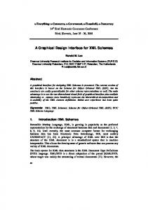
48. R1 = R1 – {r}; 49. } 50. for each a ∈ A { /* the remaining relationships are all 1:1 51. if st(a)= “atomic” apply Rule 12 to generate and nest an element/attribute for a; 52. else apply Rule 11 to generate and nest an element for a; 53. A = A – {a}; 54. } Output: the root element named nd for δ in the target XML schema 4.2 Transformation Example Figure 1 shows an E-R diagram named company. The keys and local keys for regular and weak entity sets are underlined with solid and dotted lines, respectively. Given this E-R diagram as input to the ERD2XSD algorithm, the XML schema with the following root element will be generated. ssn n emp supervise 1 mgr
.....
name clerk
employee
ISA manager
dependentOf
n
workFor
1
1
manage
1
department
workTime n worksOn
dependent
deptID name
1
startDate
n job
1 control n project
duration
projID name
name ......... jobID
hourlyRate
Fig. 1. An example E-R diagram company
Designing Quality XML Schemas from E-R Diagrams
517
… …
518
C. Liu and J. Li
5 Conclusion In this paper, we first discussed design criteria of a good quality XML schema. Then, we designed transformation rules that translate all the constructs of an E-R model into their counterparts in XML Schema. We claimed that these set of rules follow all five criteria discussed in the paper, i.e., information preservation, highly nested structures, no redundancy, consideration of dominant applications, and design reversibility. Based on the transformation rules, a recursive algorithm called ERD2XSD was proposed that takes an arbitrary E-R diagram as input and generates a correspondent high quality XML schema as output. An illustrative example was given in the end. In the future, we will build a prototype using this algorithm and improve it as a real XML schema design tool.
Designing Quality XML Schemas from E-R Diagrams
519
Acknowledgement This work was supported by the Australian Research Council Discovery Project under the grant number DP0559202.
Reference 1. C. Kleiner and U. W. Lipeck: Automatic Generation of XML DTDs from Conceptual Database Schemas. GI Jahrestagung (1) 2001. pp. 396-405. 2. C. M. Sperberg-McQueen, E. Maler, T. Bray, J. Paoli and F. Yergeau: Extensible Markup Language (XML) 1.0 (Third Edition). W3C Recommendation, 2004. http://www.w3.org/ TR/REC-xml/. 3. L. Bird, A. Goodchild and T. A. Halpin: Object Role Modeling and XML-Schema. ER 2002. pp. 309-322. 4. P. Bernus, K. Mertins and G. Schmidt: Handbook on Architecture of Information Systems. Chapter 4. pp. 81-101. Springer-Verlag, Berlin, 1998. 5. V. Turau: Making Legacy Data Accessible for XML Applications. 2001. http://www.informatik.fh-wiesbaden.de/~turau/DB2XML/. 6. D. Lee, M. Mani, F. Chiu and W. Chu: NeT & CoT: Translating Relational Schemas to XML Schemas using Semantic Constraints. CIKM 2002. pp. 282-291. 7. C. Baru: XViews: XML Views of Relational Schemas. DEXA Workshop. 1999. pp. 700-705. 8. C. Liu, M. W. Vincent and J. Liu: Constraint Preserving Transformation from Relational Schema to XML Schema. World Wide Web Journal, 9(1):93-110, March 2006. 9. D. Beech, N. Mendelsohn, M. Maloney and H. S. Thompson: XML Schema Part 1: Structures Second Edition, W3C Recommendation, http://www.w3.org/TR/xmlschema-1/. 10. P. Bohannon, W. Fan, M. Flaster and P. P. S. Narayan: Information Preserving XML Schema Embedding. VLDB 2005. pp. 85-96. 11. D. Barbosa, J. Freire and A. O. Mendelzon: Designing Information-Preserving Mapping Schemas for XML. VLDB 2005. pp. 109-120. 12. P. Atzeni, S. Ceri, S. Paraboschi and R. Torlone: Database Systems Concepts, Languages & Architectures, part 2. pp. 163-179. McGraw-Hill International (UK) Limited, 1999.