International Journal of Mechanical Engineering and Applications 2013; 1(2): 59-63 Published online June 30, 2013 (http://www.sciencepublishinggroup.com/j/ijmea) doi: 10.11648/j.ijmea.20130102.15
Detect tool breakage by using combination neural decision system & Anfis tool wear predictor Soheil Mohtaram1, Mohammad Amin Nikbakht2 1 2
Mechanical engineering, Islamic azad university science & Research branch, Yazd, Iran Mechatronic engineering, Islamic azad university of khomeinishahr, Isfahan, Iran
Email address:
[email protected](S. Mohtaram),
[email protected](M. A. Nikbakht)
To cite this article: Soheil Mohtaram, Mohammad Amin Nikbakht. Detect Tool Breakage By Using Combination Neural Decision System & Anfis Tool Wear Predictor. International Journal of Mechanical Engineering and Applications. Vol. 1, No. 2, 2013, pp. 59-63. doi: 10.11648/j.ijmea.20130102.15
Abstract: The original contribution of the research is the developed monitoring system that can detect tool breakage in real time by using a combination of neural decision system and ANFIS tool wear predictor. The ANFIS method uses the relationship between flank wear and the resultant cutting force to estimate tool wear. Therefore, the ANFIS method is used to extract the features of tool states from cutting force signals. A neural network is used in tool condition monitoring system (TCM) as a decision making system to discriminate different malfunction states from measured signal. A series of experiments were conducted to determine the relationship between flank wear and cutting force as well as cutting parameters. The forces were measured using a piezoelectric dynamometer and data acquisition system. Simultaneously flank wear at the cutting edge was monitored by using a tool maker’s microscope. The experimental force and wear data were utilized to train the developed simulation environment based on ANFIS modeling. By developed tool condition monitoring system (TCM) the machining process can be on-line monitored and stopped for tool change based on a pre-set tool-wear limit. Keywords: Machining Process, Simulation, Wear Estimation, ANFIS
1. Introduction The main goal of development of tool condition monitoring systems (TCM) is to increase productivity and hence competitiveness by maximizing tool life, mini missing down time, reducing scrap page and preventing damage. The traditional ability of the operator to determine the condition of the tool based on his experiences and senses is now the expected role of the monitoring system. Each tool condition monitoring (TCM) system consists of: sensors, signal conditioners/amplifiers and a monitor. The monitor uses a strategy to analysis the signals from the sensors and to provide reliable detection of tool and process failures. It can be equipped with some signal visualization system and is connected to the machine control. Many studies have been conducted on the monitoring of malfunctions and abnormal cutting states of machine tools[1]. With regard to the monitoring of cutting tool states, two main factors are tool wear and failure. Tool failure has become more important recently since hard tools are frequently used in the cutting process.
There are two techniques for tool wear sensing: direct and indirect. Generally direct measurements are avoided because of difficulty of online measurements. For indirect methods of TCM, the following steps are followed: use of single or multiple sensors[2] to capture process information; use of signal processing methods to extract features from the sensor information; use of decision-making strategy to utilize extracted featured for prediction of tool failure. Indirect technique includes measuring of cutting forces, torque, vibration, acoustic emission (stress wave energy), sound, temperature variation of the cutting tool, power or current consumption of spindle or feed motors and roughness of the machined surface[3]. The recent trend in TCM is multisensory approach which is termed as sensor fusion /sensor integration/sensor synthesis. The idea is to gather information from several sensors to make a comprehensive estimate of tool wear. The application of TCM in industry have relied mostly on robust and reliable sensor signals such force, power and AE. They are relatively easy to install in existing or new machines, and do not influence machine integrity and stiffness.
60
Soheil Mohtaram et al.: Detect Tool Breakage by Using Combination Neural Decision System & Anfis Tool Wear Predictor
The recent studies show that force signals contained the most useful information for determining the tool condition[4]. However, in many cases the use of force sensors is not practical for retrofit applications and spindle power signal is often used as an alternative. Several different approaches have been proposed to automate the tool monitoring function. These include classical statistical approaches as well as fuzzy systems and neural networks. For instance Iqbal[5] developed an approach based on the least-squares regression for estimating tool wear in machining while. The capacity of artificial neural networks to capture nonlinear relationships in a relatively efficient manner has motivated Chien and Tsai[6] to apply these networks for developing tool wear prediction models. But in such models, the nonlinear relationship between sensor readings and tool wear embedded in a neural network remains hidden and inaccessible to the user. In this research we attempt to solve this situation by using the Adaptive Neuro-Fuzzy Inference System (ANFIS) to predict the flank wear of the tool in end-milling process. This model offers ability to estimate tool wear as its neural network based counterpart but provides an additional level of transparency that neural networks fails to provide. Then a neural network is used as a decision making system to predict the condition of the tool. In this study, the cutting forces are used as the indicator of the tool flank wear variation.
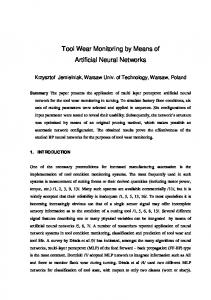
2. Problem Definition End-milling is interrupted cutting process, which means that each cutting tooth generates a cyclic cutting force ranging from negative to maximum force, and back to negative. This force is graphed as a series of peaks (Fig. 1).
experiment for detecting tool state. If the tool condition is good, the peak measurement of each tooth’s force should be roughly the same during one revolution of the cutter. If a tooth is broken, it generates a smaller peak force because it carries a smaller chip load. As a result, the tooth that follows a broken tooth generates a higher peak force as it extracts the chip that the broken tool could not. One main force principle can be used to detect tool condition: Maximum peak force in each revolution should differ between good and broken tools. Maximum peak force of a broken tool must be larger than that of a good tool; Applying these principles, an in-process tool breakage monitoring system was developed for end milling operations. The cutting forces and machining parameters were selected as input factors.[7]
3. TCM Methodology and Structure The proposed approach consists of two main steps: First, an ANFIS model of tool wear is developed from a set of data obtained during actual machining tests performed on a Heller milling machine using a Kistler force sensor. The trained ANFIS model of tool wear is then subsequently merged with a neural network for estimating tool wear condition (fresh, worn). Fig. 2 shows the basic architecture of the proposed system. This is a typical TCM system where the sensor is used to collect the signals during milling through a data acquisition module. The signal processing module analyses the machining signals for extracting features sensitive to tool wear.[8] The features together with the machining parameters constitute the data set to be used as input to the decision system and estimator. The main purpose of the decision system and estimator is to map the input features to the current state of tool .i.e. the amount of tool wear. A multi-layer perception neural network with back propagation algorithm is used in TCM as a decision system due to its ability of learning, noise suppression and parallel processing. A random pattern classifier module divides the data into training and testing set. The training set is used for learning purpose while the testing set is used for testing the decision system performance.[9] 3.1. ANFIS Based Tool Wear Predictor
Fig 1. Cutting force signal of a good and damaged cutter
Cutting parameters and tool conditions affect the magnitude of resultant force. Therefore, the resultant force FR, generated from X and Y directions, is used in this
The relationship between the machining parameters/sensor signals and flank wear is first captured via a network and is subsequently reflected in linguistic form with the help of a fuzzy logic based algorithm. The estimation design process consists of a linguistic rule construction, partition of fuzzy subsets and the definition of the membership function shapes.
International Journal of Mechanical Engineering and Applications 2013; 1(2): ): 59-63
v, f, RD, AD
Cutting parameters
CNC control
61
Tool condition / Action Normal / no Broken / stop (f=0) Worn / w B=_mm
RS-232
HMI interface Control pannel TCM
Force signals
Fx,Fy,Fz
Data acquisition module
ANN decision making system
Signal processing module
ANFIS wear predictor
Machine tool
Fig 2. Architecture of tool condition monitoring system
It uses training examples as input and constructs the fuzzy if–then then rules and the membership functions (MF) of the fuzzy sets involved in these rules as output. This process is called a training phase. In this model, we adopted adopt two different types of membership functions for analysis in ANFIS training and compared their differences regarding the accuracy rate of the flank wear prediction. After training the estimator, its performance was tested under various cutting conditions.. The performance of this method turned out to be satisfactory for evaluating of flank wear, within a 5% mean percentage error.[10] Fig. 3 shows the fuzzy rule architecture of ANFIS when the triangular membership function is adopted. The architectures shown wn in Fig. 3 consist of 31 fuzzy rules. ANFIS applies Hybrid Learning method for updating parameters. For premise parameters that define membership functions, ANFIS employs gradient descent to fine-tune fine them. For consequent parameters that define the coefficients icients of each output equations, ANFIS uses the leastleast squares method to identify them. This approach is thus called Hybrid Learning.
depths of cut,, (4) forces, (5) tool wear. Output layer consist of only two neurons: (1) normal and (2) broken/worn. In steps two the learning rate, momentum factor and the number of hidden layers/hidden neurons were defined. The number of hidden neurons was set at 12, the learning rate was set at 1, and the momentum item was 0.4. The number of training/testing cycles was 1700. In step 3 the data set was divided into training and testing set. 200 data points were used in this research. Good tools collected half of these and broken tools collected the rest. In step 4 the training and testing phase is accomplished. Finally in the last step the trained neural network was used to predict tool conditions[11]
3.2. Neural Decision System Development A neural decision-making making system was developed in Matlab software. The neural network rk used to predict the cutting tool condition is shown in Fig. 3. It has tooltool breakage detection capability and is based on pattern recognition. The neural network stores a number of reference force patterns that are characteristic of tool breakage. When a tool tooth breaks, cutting force suddenly rises for a while, and then drops to zero. The system continuously monitors the signal for the break pattern. If pattern is identified, a break is declared within 10 ms of the breakage. Four steps are required to develop a neural decision system. In step one, network architecture and prediction factors were selected. Network has two hidden layers and uses a set of 5 normalized inputs for tool condition prediction: (1) cutting speed, (2) feed rate, (3)
Fig 3. Components of TCM
62
Soheil Mohtaram et al.: Detect Tool Breakage by Using Combination Neural Decision System & Anfis Tool Wear Predictor
4. Experimental Design Monitoring experiments were performed on a HELLER machine tool (type BEA1) with FAGOR CNC controller. It involved an end milling process of steel parts using two end mill cutters: normal and on tooth broken. The cutting tool used in the machining test was a solid end-milling cutter (R216.24-16050 IAK32P) with four cutting edges. The tool diameter was 16 mm. Its helix angle was 10°. The corner radius of the cutter was 4 mm. The insert had an outer coated layer of Tin featuring low friction and welding resistance. The work piece material used in the machining test was Ck 45 and Ck 45 (XM) with improved machining properties. The work piece was mounted in a 3 component piezoelectric dynamometer (Kistler 9255) to monitor the cutting forces in the X and Y directions. Force dynamometer was mounted on the machining table and connected to a 3-channel charge amplifier. The signals were monitored using a fast data acquisition card (National Instruments PC-MIO-16E-4) and software written with The National Instruments CVI programming package. The experimental set-up is shown in Fig. 2. The flank wear was observed during the experiments. The cutting tool flank wear was discontinuously measured with a tool microscope of 0.01 mm accuracy. The machining tests were carried out in two types of end milling operations: down milling and up milling operations. The experiments were carried out for all combinations of the chosen cutting parameters and tool wear.
neural network was mapped as 0.01 for the normal cutting state, and 0.99 for the tool breakage. When the neural network outputs are over 0.9 (tool breakage), it sends the signal “Tool broken” to the PC. When both the neural network outputs are below 0.9, it sends the signal “Tool condition Normal”. Figs. 4a and 4b represent the cutting force signals for the normal and broken cutter. Developed decision system incorporates simple fixed limits for tool breakage detection. Limits are: L1 (collision), L2 (tool fracture), L3 (worn tool) and L4 (missing tool limit). In future it will be appropriate to replace fixed limits with self-adjusting limits. The detection system demonstrated a very short response-time to tool conditions. Because tool conditions could be monitored in a real-time, the worn tool could be replaced immediately to prevent damage to the product and machine.
5. Results and Discussion In-process sensing technique in connection with decision-making system is essential for successful working of TCM. The neural network was capable of detecting tool conditions accurately in real time. The accuracy of training data was 98.1%, and the accuracy of testing data was 94.9%. The results of neural network testing are shown in Table 1. The output node value of a back-propagation
Fig 4. Thrust force of normal (a) and broken (b) tool in real time monitoring; (c) Indicative tool breakage force pattern with limits
Table 1. Partial results of TCM testing
Input factors
ANN Prediction
ANFIS Prediction WB [mm]
Normal Broken Broken Broken Normal Broken Normal Broken Normal Broken
0.11 0.24 0.17 0.26 0.13 0.27 0.15 0.23 0.14 0.31
ANN outputs
Tool conditions
F [N]
N (min-1)
F [mm/rev]
AD [mm]
RD [mm]
ANN1
ANN2
Normal Broken Normal Broken Normal Broken Normal Broken Normal Broken
427.2 777.9 433.9 729.6 650.5 925.7 614.4 751.9 904.3 991.9
440 440 440 440 440 440 480 480 360 360
0.17 0.17 0.13 0.13 0.20 0.20 0.20 0.20 0.22 0.22
1.2 1.2 1.4 1.4 1.4 1.4 1.4 1.4 1.6 1.6
8 8 8 8 8 8 8 8 8 8
0.9 0.02 0.3 0 0.89 0 0.88 0.03 0.89 0
0.1 0.98 0.7 1 0.11 1 0.12 0.97 0.11 1
International Journal of Mechanical Engineering and Applications 2013; 1(2): 59-63
economics of machining, Journal of Mechanical Engineering, Vol.48, No 3, pp 72-79.
6. Conclusion We developed a system for monitoring tool condition in real time and obtained the following result through verification experiments: (1) The proposed monitoring system of cutting process may be very useful because of its parallel processing capability; (2) It enables monitoring of the cutting process with high reliability; ANFIS component can estimate flank wear progress very fast and accurately, once the maximum cutting forces are known. A monitoring system using a neural network is able to classify the various cutting states such as tool breakage, and tool wear.
References [1]
[2]
[3]
[4]
MULC, T., UDILJAK, T., CUS, F., MILFELNER, M. (2004) Monitoring cutting- tool wear using signals from the control system, Journal of Mechanical Engineering, Vol.50, No.12, pp 568-579 KUO, R.J. (2003) Multi-sensor integration for on-line tool wear estimation through artificial neural networks and fuzzy neural network, Engineering Applications of Artificial Intelligence, Vol.3, pp 49-261 ACHICHE, S., BALAZINSKI, M., BARON, L., JEMIELNIAK, K. (2008) Tool wear monitoring using genetically-generated fuzzy knowledge bases, Engineering Applications of Artificial Intelligence, Vol.15, pp 303-314 KOPAC, J. (2002) Cutting forces and their influence on the
63
[5]
IQBAL, A., HE, N., DAR, N.U., LI, L. (2009) Comparison of fuzzy expert system based strategies of offline and online estimation of flank wear in hard milling process, Expert Systems with Applications, Vol.33, pp 61-66
[6]
CHIEN, W.T., TSAI, C.S. (2005) The investigation on the prediction of tool wear and the determination of optimum cutting conditions in machining 17-4PH stainless steel, Journal of Materials Processing Technology, Vol.140, pp 340-345
[7]
A.Chiba, T.Fukao, O.Ichikawa, M. Oshima, M. Takemoto & D.G.Dorrell, (2005), Magnetic bearing and bearing less drives Dreier, M. E., McKeown,W. L. and Scott, H. W. (1996) A fuzzy logic controller to drill small holes.In Chen, C. H. (ed.), Fuzzy Logic and Neural Network Handbook. New York: McGraw-Hill, pp. 22.1–22.8.
[8]
Aspin wall DK, Dewesa RC, Ng EG, Sage C, Soo SL (2007) the influence of cutter orientation and work piece angle on mach inability when high-speed milling Inconel 718 under finishing conditions. Int J Mach Tools Manuf 47:1839–1846.
[9]
Rech J, Kermouche G, Carcia-Rosales C, Khellouki A, Garcia-NavasV (2008) Characterization and modeling of the residual stresses induced by belt finishing on a AISI52100 hardened steel. J Mater Process Techno doi: 10.1016/j.jmatprotec.2007.12.133
[10] El Mansori M, Sura E, Ghidossi P, Deblaise S, Dal Negro T, Khanfir H (2007) Toward physical description of form and finish performance in dry belt finishing process By a triboenergetic approach. J Mater Process Technol 182:498–511. [11] Axinte DA, Kritmanorot M, Gindy NNZ (2005) Investigations on belt polishing of Heat-resistant titanium alloys. J Mater Process Technol 166:398–404.